1
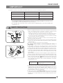
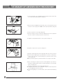
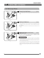
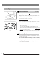
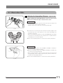
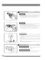
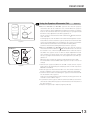
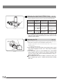
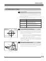
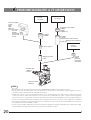
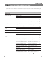
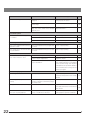
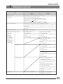
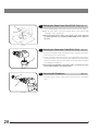
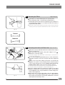
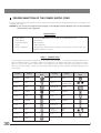
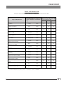
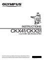
INSTRUCTIONS
CKX41/CKX31
CULTURE MICROSCOPES
This instruction manual is for the Olympus Culture Microscopes Models CKX41 and CKX31. To
ensure the safety, obtain optimum performance and to familiarize yourself fully with the use of this
microscope, we recommend that you study this manual thoroughly before operating the microscope.
Retain this instruction manual in an easily accessible place near the work desk for future reference.
AX7351
CKX41/CKX31
CONTENTS
IMPORTANT
— Be sure to read this section for safe use of the equipment. —
1-3
1
NOMENCLATURE
4-5
2
CONTROLS
6-7
3
SUMMARY OF OBSERVATION PROCEDURE
4
USING THE CONTROLS
8
9-15
4-1 Microscope Frame ............................................................................................................................................................................... 9
1 Turning On the Light Source
2 Adjusting the Brightness
3 Adjusting the Tension of the Coarse Adjustment Knob
4-2 Stage..................................................................................................................................................................................................................... 10
1 Placing the Specimen
2 Moving the Specimen
4-3 Observation Tube ....................................................................................................................................................................... 11-14
1 Adjusting the Interpupillary Distance
2 Adjusting the Diopter
3 Using the Eye Shades
4 Using Eyepiece Micrometer Disks
5 Selecting the Light Path (U-TR30-2 Only)
6 Adjusting the Tilt
4-4 Illumination Column........................................................................................................................................................................ 15
1 Using the Filters
2 Using the Aperture Iris Diaphragm
3 Removing the Condenser Lens
4-5 Objective Correction Collars ............................................................................................................................................. 16
1 Correction Collar
5
PHASE CONTRAST OBSERVATION
6
PHOTOMICROGRAPHY & TV OBSERVATION
7
TROUBLESHOOTING GUIDE
21-22
8
SPECIFICATIONS
23-24
9
ASSEMBLY — See this section for the replacement of the light bulb. —
25-29
17-19
20
PROPER SELECTION OF THE POWER SUPPLY CORD........................................................ 30-31
CKX41/CKX31
IMPORTANT
The difference between the CKX31 and CKX41 microscopes lie in the following basis systems.
CKX31
CKX41
Observation tube
Binocular tube fixed
Replaceable*
Stage center plate
–
Replaceable**
Not mountable
Mountable
Reflected fluorescence system
* The U-CBI30-2/U-BI30-2/U-CTBI/CKX-TBI binocular tube or U-CTR30-2/U-TR30-2 trinocular tube can be
mounted. But no intermediate attachment can be mounted.
**The standard stage center plate can be replaced with the CK40-CPG glass center plate, IX-CP50 center
plate (50 mm), etc.
SAFETY PRECAUTIONS
³
²
@
Fig. 1
5
4
Fig. 2
1. After the equipment has been used in an observation of a specimen
that is accompanied with a potential of infection, clean the parts
coming in contact with the specimen to prevent infection.
· Moving this product is accompanied with the risk of dropping the specimen. Be sure to remove the specimen before moving this product.
· In case the specimen is damaged by erroneous operation, promptly
take the infection prevention measures.
2. Install the microscope on a sturdy, level table or bench (Weight: CKX31
about 8 kg, CKX41 about 8.8 kg).
3. When transporting the microscope, be sure to keep it horizontal by holding
it by the root of the observation tube relay tube 1 and the illumination
column 2. (Fig. 1)
Be sure to remove the specimen since it may fall.
# Do not tilt it during carrying to prevent damaging the desktop or
microscope.
4. Culture liquid or water spilt on the stage, objective or microscope frame
may damage the equipment. Immediately disconnect the power cord
from the wall outlet and wipe the liquid or water off if it is spilt on them.
5. The surfaces of the lamp socket 3 of the illumination column will become
extremely hot during operation. When installing the microscope, make
sure to allow ample free space around and in particular above the lamp
socket. (Fig. 1)
When using the TV camera or photomicrographic system, install them so
that the connection cable does not come in contact with the lamp socket.
6. To avoid potential shock hazards and burns when replacing the light
bulb, set the main switch 4 to “ ” (OFF) then disconnect the power cord
from the wall outlet in advance. Whenever you replace the bulb during
use or right after use, allow the lamp socket 3 and bulb to cool before
touching. (Figs. 1 & 2)
Designated
bulbs:
6V30WHAL high-intensity halogen bulb
(PHILIPS 5761)
7. Always use the power cord provided by Olympus. If no power cord is
provided, please select the proper power cord by referring to the section
“PROPER SELECTION OF THE POWER SUPPLY CORD” at the end of
this instruction manual. If the proper power cord is not used, product
safety performance cannot be warranted.
8. Always ensure that the grounding terminal of the microscope and that
of the wall outlet are properly connected. If the equipment is not grounded,
Olympus can no longer warrant the electrical safety performance of the
equipment.
1
9. The microscope system is unstable when the large camera back
is attached. When pulling out the film, be sure to hold the microscope with one hand.
10. Always turn the light intensity control knob 5 gently. Do not attempt to turn it beyond the stop position. (Fig. 2)
Safety Symbols
The following symbols are found on the microscope. Study the meaning of the symbols and always use the equipment
in the safest possible manner.
Symbol
Explanation
Indicates that the surface becomes hot, and should not be touched with bare hands.
Before use, carefully read the instruction manual. Improper use could result in personal injury to
the user and/or damage to the equipment.
Indicates that the main switch is ON.
Indicates that the main switch is OFF.
Warnings
Warning engraving is placed at parts where special precaution is required when handling and using the microscope.
Always heed the warnings.
Warning engraving
position
1
Lamp socket (U-LS30-3)
[Warning against high temperature]
Getting Ready
1. A microscope is a precision instrument. Handle it with care and avoid subjecting it to sudden or severe impact.
2. Do not use the microscope where it is subjected to direct sunlight, high temperature and humidity, dust or vibrations. (For
the operating conditions, see chapter 8, “SPECIFICATIONS”.)
3. Use the tension adjustment ring to adjust the rotation tension of the coarse adjustment knob.
4. For the applicable objectives, see chapter 8, “SPECIFICATIONS”. Olympus cannot guarantee the performance when other
objective than specified is used.
2
CKX41/CKX31
2
Maintenance and Storage
1. Clean all glass components by wiping gently with gauze. To remove fingerprints or oil smudges, wipe with gauze slightly
moistened with a mixture of ether (70%) and alcohol (30%).
Since solvents such as ether and alcohol are highly flammable, they must be handled carefully. Be sure to keep
these chemicals away from open flames or potential sources of electrical sparks –– for example, electrical
equipment that is being switched on or off. Also remember to always use these chemicals only in a well-ventilated
room.
2. Do not attempt to use organic solvents to clean the microscope components other than the glass components. To clean
them, use a lint-free, soft cloth slightly moistened with a diluted neutral detergent.
3. Be careful not to spill any liquid –– such as a culture solution –– on the unit. If you do spill anything, immediately set the
main switch to “ ” (OFF) and unplug the power cord. Then wipe away any liquid on or under the objectives.
4. If no objectives are mounted, be sure to cover the objective mounting threaded positions on the revolving nosepiece to
prevent and dust and spilled culture solution from getting on the lenses inside.
5. Do not disassemble any part of the microscope as this could result in malfunction or reduced performance.
6. When not using the microscope, keep it covered with a dust cover. Make sure the lamp socket is cool before covering the
microscope.
7. Using a device that radiates ultraviolet light such as a germicidal lamp near the microscope may discolor (yellow) parts
of the microscope surface. The amount of discoloration depends on the radiation intensity of the ultraviolet light and the
distance between the microscope and radiation source. When not using the microscope, cover it with the dust cover. We
recommend that you also cover the microscope with an impermeable sheet.
3
Caution
If the microscope is used in a manner not specified by this manual, the safety of the user may be imperiled. In addition,
the equipment may also be damaged. Always use the equipment as outlined in this instruction manual.
The following symbols are used to set off text in this instruction manual.
: Indicates that failure to follow the instructions in the warning could result in bodily harm to the
user and/or damage to equipment (including objects in the vicinity of the equipment).
# : Indicates that failure to follow the instructions could result in damage to equipment.
} : Indicates commentary (for ease of operation and maintenance).
This device complies with the requirements of directive 98/79/EC concerning in vitro diagnostic
medical devices. CE marking means the conformity to the directive.
NOTE: This equipment has been tested and found to comply with the limits for a Class A digital device,
pursuant to Part 15 of the FCC Rules. These limits are designed to provide reasonable protection
against harmful interference when the equipment is operated in a commercial environment. This
equipment generates, uses, and can radiate radio frequency energy and, if not installed and used in
accordance with the instruction manual, may cause harmful interference to radio communications.
Operation of this equipment in a residential area is likely to cause harmful interference in which case
the user will be required to correct the interference at his own expense.
FCC WARNING: Changes or modifications not expressly approved by the party responsible for compliance
could void the user’s authority to operate the equipment.
3
NOMENCLATURE
CKX31
Lamp Socket
Phase Contrast Slider
U-LS30-3
· Pre-centered Ph slider: IX2-SLP
· Ph centering slider: IX2-SL
Objectives
For brightfield observation:
PlanCN 4X
PlanCN 10X
PlanCN 20X
PlanCN 40X
PlanCN 60X
PlanCN 100XO
#Dedicated objectives are required
for phase contrast observations
(see page 17).
Illumination
Column (Fixed)
Eyepieces (10X)
Binocular Tube (Fixed)
Ultralong Working
Distance Condenser
Microscope Frame
· CKX31SF
Revolving Nosepiece (Fixed)
Quadruple revolving nosepiece
Stage (Fixed)
· Stage extension plate: CK2-SS
· Mechanical stage: CK40-MVR
4
CKX41/CKX31
CKX41
Lamp Socket
Phase Contrast Slider
U-LS30-3
· Pre-centered Ph slider: IX2-SLP
· Ph centering slider: IX2-SL
Objectives
Illumination Column
(Fixed)
For brightfield observation:
PlanCN 4X
PlanCN 10X
PlanCN 20X
PlanCN 40X
PlanCN 60X
PlanCN 100XO
#Dedicated objectives are required for phase
contrast observations (see page 17).
Ultralong Working
Distance Condenser
Eyepieces
· WHB10X*
· WHN10X/WHN10X-H**
Stage Center Plate
· Standard stage center
plate
· Glass stage center plate:
CK-40CPG
· Stage center plate
(50 mm): IX-CP50
Observation Tube
· Binocular tube: U-CBI30-2*/U-BI30-2**
· Trinocular tube: U-CTR30-2*/U-TR30-2**
· Tilting binocular tube: U-CTBI***/CKX-TBI*
*/** Only the eyepieces carrying the same
marking “ * " or “ ** " as the observation tube marking can be attached.
*** Dedicated 10X eyepiece built in.
Revolving Nosepiece (Fixed)
Quadruple revolving nosepiece
Microscope Frame
CKX41SF
Stage (Fixed)
· Stage extension plate: CK2-SS
· Mechanical stage: CK40-MVR
5
CONTROLS
CKX31
}If you have not yet assembled the microscope, read chapter 9, “ASSEMBLY” (pages 25 to 29).
Filter holder (Page 29)
Phase contrast slider
(Page 16)
Aperture iris diaphragm
lever (Page 15)
Interpupillary distance
scale (Page 11)
Slider centering knob
storage holes
Diopter adjustment ring
(Page 12)
Light intensity control knob
(Page 9)
Fine adjustment knob
Coarse adjustment knob
Coarse adjustment knob tension
adjustment ring (Page 9)
Main switch (Page 9)
6
CKX41/CKX31
CKX41
}If you have not yet assembled the microscope, read chapter 9, “ASSEMBLY” (pages 25 to 29).
Filter holder (Page 29)
Interpupillary distance
scale (Page 11)
Phase contrast slider
(Page 16)
Aperture iris diaphragm
lever (Page 15)
Diopter adjustment ring
(Page 12)
Standard stage center
plate
Slider centering knob
storage holes
Light intensity control knob
(Page 9)
Fine adjustment knob
Coarse adjustment knob
Coarse adjustment knob tension
adjustment ring (Page 9)
Main switch (Page 9)
7
SUMMARY OF OBSERVATION PROCEDURE
1. Set the main switch 1 to “ I ” (ON) and turn the light intensity control knob
2 to obtain appropriate brightness. (Page 9)
²
@
2. When using the U-TR30-2 trinocular tube, push in the light path selector
knob 3 to set the light path at 100% for binocular observation. (Page 14)
³
3. Place a specimen on the stage. (Page 10)
4. Turn the revolving nosepiece to bring the 10X objective into the light path.
Be sure to turn the revolving nosepiece until it clicks.
5. Adjust the interpupillary distance of the eyepieces. (Page 11)
6. Adjust the diopter of the eyepieces. (Page 12)
7. Bring the required objective into the light path and focus on the specimen.
8. When using the 40X objective provided with the correction collar, set the
scale on the correction collar according to the thickness of the vessel
bottom. (Page 16)
}When performing phase contrast observation, see pages 17 and after.
|
8
9. When observing an undyed specimen with brightfield, stop down the
aperture iris diaphragm 4. In phase contrast observation, set the aperture
wide open. (Page 15)
Bring the required filter into the light path. (Page 15)
10. In brightfield observation, use the LBD filter. In phase contrast observation,
use the IF550 green filter as required.
}In photomicrography, it is recommended to use the 45HA heat absorbing
filter.
CKX41/CKX31
USING THE CONTROLS
4-1 Microscope Frame
1
Turning On the Light Source
(Fig. 3)
Set the main switch 1 on the side panel of the microscope frame to “ I ”
(ON).
@
Fig. 3
2
Adjusting the Brightness
(Fig. 4)
Turn the light intensity control 1 clockwise to raise the voltage and increase
the brightness. Turn it counterclockwise to lower the voltage and decrease
the brightness.
}The service life of the bulb can be extended by using the bulb at a lower
voltage.
@
Fig. 4
the Tension of the Coarse
3 Adjusting
Adjustment Knob
(Fig. 5)
# Be sure to use the tension adjustment ring 1 to adjust the rotation
tension of the coarse adjustment knob.
Adjustment Procedure
@
Fig. 5
Turn the tension adjustment ring 1 with your fingers or using a flat-blade
screwdriver. When the ring is turned in the direction of the arrow, tension
of the coarse adjustment knob increases. Turning the ring in the opposite
direction decreases the tension.
If the revolving nosepiece descends on its own or if the specimen gets
out of focus quickly even when it is brought into focus using the fine
adjustment knob, it means that the tension of the coarse adjustment
knob is too low. Turn the ring in the direction of the arrow to increase the
tension.
9
4-2 Stage
1
@
Placing the Specimen
(Figs. 6 & 7)
Put the specimen in the center of the stage.
When Using a
35 mm Petri Dish
}With the CKX41, a 35 mm petri dish can be mounted directly on the
stage provided that the standard stage center plate is in use.
1. With the CKX31, put the provided 35 mm petri dish holder 1 on the stage
and mount the 35 mm petri dish on the opening in the center.
2. To move the petri dish, slide the entire holder.
Fig. 6
Using the Mechanical Stage
1. When using a 96-well or 24-well micro-titer plate, extend the specimen
holder 2 to directly hold the micro-titer plate. (Fig. 7)
2. To hold any other type of plate, combine one of the following provided
holders with the mechanical stage.
· Terasaki holder 3 (AB4488): For Terasaki plate, 35 mm petri dish holder
4 or 65 mm petri dish.
· Slide glass holder 5 (AB4489): For slide glass, 54 mm petri dish.
· Blood cell test plate holder IX2-BCTP 6 (optional):For a blood cell test
plate holder or other calculating chamber for bacteria and eosinophil
+0.3
+0.3
with mounting section dimensions corresponding to H 77 0 x V 35 0
x D 2 mm, or for a 60mm petri dish.
3. The specimen can be moved to the desired position by turning the X-axis
knob 7 and Y-axis knob 8 (Stroke: 120 mm in X-axis direction, 78 mm in
Y-axis direction).
|
²
³
5
6
8
7
Fig. 7
2
Moving the Specimen
Turn the X-axis and Y-axis knobs of the mechanical stage or move the
specimen directly by hand.
# Be careful when changing objectives. When objectives are switched
after observing the specimen with an objective with short working
distance, the newly selected objective may interfere with the stage
center plate or petri dish holder.
}With the CKX41, the IX-CP50 stage center plate ( 50 mm) allows a wide
range of use without interference.
10
CKX41/CKX31
4-3 Observation Tube
1
Adjusting the Interpupillary Distance
(Figs. 8 to 10)
When adjusting the interpupillary distance, take care not to let your
fingers get caught in the gaps of the binocular section.
With the CKX31
While looking through the eyepieces, move both eyepieces until the left
and right fields of view coincide completely.
Adjust so that the two index dots · 1 are horizontal. (Fig. 9)
Fig. 8
}To make the line connecting the two index dots horizontal, adjust so that
the index dots come on the extension of one of the horizontality lines
inscribed on the pivot.
When your interpupillary distance is other than 50, 60, 70 and 75, adjust
so that the line connecting the two index dots are in parallel with the
horizontality lines on the pivot. (Fig. 9)
}Note your interpupillary distance so that it can be quickly duplicated.
@
Fig. 9
With the CKX41
}When the observation tube is the U-CBI30-2, U-CTR30-2 or U-CTBI, follow the procedure in "With the CKX31".
}When the observation tube is the U-BI30-2, U-TR30-2 or CKX-TBI only
one index dot is provided. (Fig. 10)
· While looking through the eyepieces, move both eyepieces until the left
and right fields of view coincide completely. The position of index dot ·
indicates the interpupillary distance.
}Note your interpupillary distance so that it can be quickly duplicated.
Fig. 10
11
@
2
Adjusting the Diopter
(Figs. 11 to 13)
With the CKX31
1. While looking through the left eyepiece with your left eye, turn the coarse
and fine focus adjustment knobs to bring the specimen into focus.
2. While looking through the right eyepiece with your right eye, turn only the
diopter adjustment ring 1 to focus on the specimen. (Fig. 11)
Fig. 11
With the CKX41
²
}When the U-CTBI is used, align the white dot · with the index line on the
scale of the right eyepiece’s diopter adjustment ring.
1. While looking through the right eyepiece with your right eye, turn the coarse
and fine focus adjustment knobs to bring the specimen into focus.
2. While looking through the left eyepiece with your left eye, turn only the
diopter adjustment ring 2 to focus on the specimen. (Fig. 12)
Fig. 12
Using a Finder Eyepiece
}Insert the finder eyepiece into the right eyepiece sleeve of the U-TR30-2
trinocular tube.
1. Looking through the right eyepiece with your right eye, turn the eyepiece
top ring until clearly defined double crosslines can be seen in the field of
view. (Fig. 13)
2. Looking through the right eyepiece, turn the coarse and fine adjustment
knobs to bring the specimen and double crosslines into simultaneous
focus.
3. Looking through the left eyepiece with your left eye, turn the diopter adjustment ring to focus on the specimen.
Fig. 13
3
Using the Eye Shades
(Fig. 14)
When Wearing Eyeglasses
Use with the eyeshades in the normal, folded-down position. This will
prevent the eyeglasses from being scratched.
When Not Wearing Eyeglasses
Extend the folded eyeshades in the direction of the arrow to prevent
extraneous light from entering between the eyepieces and eyes.
Fig. 14
12
CKX41/CKX31
4
1
2
WHN10X-H
Fig. 15-1
WHB10X-H
4
3
5
Fig. 15-2
Using the Eyepiece Micrometer Disk
(Figs. 15)
}When the WHN10X-H (or WHN10X) eyepieces are used, an eyepiece
micrometer disk can be inserted in one of them. When the eyepiece
does not have a diopter adjustment mechanism, however, it is hard to
focus on the micrometer disk if the operator has poor eyesight. Should
that be the case, adjust the focus with eyeglasses on.
Use an eyepiece micrometer disk with a diameter of 24 mm and thickness of 1.5 mm.
Following Fig. 15-1, turn the built-in micrometer-mounting frame ² counterclockwise to remove it from the eyepiece and place a micrometer disk
@ into the mounting frame. The engraving on the eyepiece micrometer
disk should face downward in the micrometer-mounting frame.
Screw the micrometer-mounting frame back into the eyepiece.
}When the WHB10X-H (or WHB10X) eyepieces are used, an eyepiece
micrometer disk with a diameter of 20.4 mm and thickness of 1 mm can
be inserted in one of them using the 20.4RH reticle holders ³ (2-piece
set). When the eyepiece does not have a diopter adjustment mechanism, however, it is hard to focus on the micrometer disk if the operator
has poor eyesight. Should that be the case, adjust the focus with eyeglasses on.
When the reticle holders are used, the field number becomes 19.6.
The field number of the U-CTBI's built-in eyepieces is 18, so it does not
change.
1. Remove both eyepieces. (When the U-CTBI is used, remove only the
right eyepiece by unscrewing the clamping screw on it with a precision
flat-blade screwdriver.)
2. Place an eyepiece micrometer disk | in one of the reticle holders ³ so
that the engraving on the eyepiece micrometer disk faces downward.
3. Screw the reticle holder ³ containing the eyepiece micrometer disk |
into the bottom of the eyepiece.
At the end of screwing, turn the reticle holder by hooking your nail on its
notch 5 to screw it all the way in.
4. To provide the other eyepiece with the same field number, screw in the
other reticle holder, without eyepiece micrometer disk, into the bottom of
the other eyepiece.
5. Replace the eyepiece(s) in its(their) original position(s).
13
5
Selecting the Light Path (U-TR30-2 Only)
(Fig. 16)
Slide the light path selector knob 1 to select the desired light path.
Light Path
Selector Knob
@
Symbol
Intensity Ratio
Applications
Pushed in
100% for binocular
eyepieces
Observation of dark
specimens
Middle position
20% for binocular Observation of
eyepieces, 80% for bright specimens,
photography, TV
TV/photography
observation
Pulled out
100% for TV/
photography
Fig. 16
Photography, TV
observation
# The U-CTR30-2 trinocular observation tube does not have the light
path selector knob and its light intensity ratio is fixed at 50% binocular
and 50% TV/photography.
@
@
Fig. 17
14
6
Adjusting the Tilt
(Fig. 17)
}When using the U-CTBI or CKX-TBI, adjust the height and tilt of the observation tube to obtain the most comfortable viewing position.
Holding the binocular section with both hands, raise or lower it to the
desired position.
· U-CTBI/CKX-TBI: 30 to 60°
# Never attempt to force the binocular section past the upper or lower
stop position. Applying excessive force could destroy the limiting
mechanism.
# The connectable eyepieces are the WHB10X only or the CXK-TBI
and the built-in eyepieces (10X) for the U-TCBI. Combination with
any other eyepiece will result in insufficient illumination at the periphery of the field of view.
When adjusting the tilt of the U-CTBI, be careful not to have your
fingers caught by the spaces @ between the binocular assembly
and cover.
CKX41/CKX31
4-4 Illumination Column
1
Using the Filters
}Using appropriate filters according to the purposes allows you to observe
and photograph specimens more effectively. Particularly, the use of the LBD
filter is recommended in observation and photomicrography because it
renders more neutral colors.
}More than one filter can be stacked in the filter holder (Filter diameter: 45
mm. Maximum thickness of stacked filters: 11 mm).
Filter
Aperture iris
diaphragm image
70-80%
2
30-20%
Application
45IF550-W45
Monochrome contrast filter (Green)
45ND6, 45ND25
Light intensity adjustment filter
(Transmittance 6% and 25%)
45LBD2-N, 45KB
Color temperature conversion filter
(For observation and photomicrography)
45HA
(Heat absorbing filter)
Exposure time compensation in photomicrography
Using the Aperture Iris Diaphragm
(Fig. 18)
}The aperture iris diaphragm determines the numerical aperture of the
illumination system in brightfield observation. It enables you to adjust the
depth of focus, contrast and resolution according to your requirements.
· Checking the aperture iris diaphragm:
Remove the eyepiece when necessary (and insert the CT-5 or UCT30 if you have one). Then look into the eyepiece sleeve; you
will seen the field of view as shown in Fig. 18. Now adjust the
aperture iris diaphragm lever as required.
· In general, when observing a dyed specimen, set the aperture iris diaphragm to 70% to 80% of the N.A. of the objective in use. However, when
observing a culture specimen, which is not dyed, set the aperture iris
diaphragm lever toward “ ”.
Objective pupil
Fig. 18
3
Removing the Condenser Lens
(Fig. 19)
}To provide more working distance, turn the condenser’s lower section 1
in the direction of the arrow and remove it. When you do this, however,
keep in mind that proper illumination cannot be achieved. Remove the
condenser lens only when using a large culture vessel.
@
Fig. 19
15
4-5 Objective Correction Collars
1
@
²
Fig. 20
16
Correction Collar
(Fig. 20)
}A culture microscope is designed to observe specimens contained in
vessels of various bottom thickness values. In order to achieve optimum
objective performance of the culture microscope, the LUCPlanFLN20X,
40X, 60X, etc. are provided with a correction collar @.
The correction is possible according to the vessel thickness.
1. If the thickness of the vessel bottom is known: Match the correction collar
to the thickness of the vessel bottom using the collar scale ² provided.
2. If the thickness of the vessel bottom is unknown:
The optimum position for the correction collar can be obtained from the
image resolution. If a satisfactory sharp image is not obtained after focus
adjustment, rotate the correction collar to the left and right so that you
can compare the images at both sides. Reset the collar to the better
image, then starting from this position, further rotate the collar to the left and
right until both images can be obtained for comparison. By repeating this
procedure several times, you will find best position for the correction collar.
Refocus after rotating the correction collar.
CKX41/CKX31
PHASE CONTRAST OBSERVATION
The following two slider units are available for phase contrast observation. Mount a slider onto the microscope and replace
the objectives with phase contrast compatible objectives.
Model Name
Description
Applicable Objectives (Note)
Ph precentering slider
IX2-SLP
· The light annuli are precentered, so no adjustment
is required. (For 4X, for 10X/20X/40X, and empty
position)
· The empty position can be used as a filter holder.
UPlanFLN4XPhP
CAchN10XPhP
LCAchN20XPhP
LCAchN40XPhP
Ph centering slider
IX2-SL
· The light annulus has to be centered. (For PHL,
for PHC/PH1, and for PH2/empty)
· The empty position can be used as a filter holder.
UPlanFLN4XPh (PHL)
CPlanN10XPh (PHC)
LCAchN20XPh (PHC)
PlanN10XPh (PH1)
LUCPlanFLN 20XPh (PH1)
LCAchN40XPh (PH2)
(Note) Only the four objectives listed can be used with the IX2-SLP. If other objective is used, the phase contrast effect cannot
be obtained.
1
Names of Parts
Phase Sliders
Ph precentering slider IX2-SLP
For 4X
(fixed)
Empty
For 10X, 20X or 40X
(fixed)
Ph centering slider IX2-SL
Optical element
IX2-SLPHC
IX2-SLPH1
Optical element
IX2-SLPH2
For PHL
(built in)
Centering knobs
# The IX2-SLPH2 does
not need centering.
17
@
³
2
²
Fig. 21
3
@
²
Fig. 22
18
(Fig. 21)
}When the IX2-SL phase contrast slider is used, it is required to attach an
optical element matching the phase objective in use.
1. Hold the IX2-SLPH2 optical element 1 so that engraving faces upward
and drop in the optical element in the empty position 2.
2. When mounting the IX2-SLPHC or IX2-SLPH1 optical element 3, insert
the provided centering knobs into the screw holes 5, loosen them fully
before dropping the optical element in the empty position 4 so that the
engraving faces upward.
3. After dropping in the optical element, lightly tighten the centering knobs.
|
5
Mounting the Optical Element
Mounting the Phase Slider
(Fig. 22)
1. Hold the phase slider 1 face up (engraving side up) with the finger hold
on the right, and insert it into the illumination column slot.
2. When performing phase contrast observation, always set the aperture iris
diaphragm lever 2 to “(” (wide open).
CKX41/CKX31
@
²
Fig. 23
³
|
Fig. 24
4
Centering the Light Annulus
(Figs. 23 & 24)
# The IX2-SLP does not need to be centered.
However, as the phase contrast effect near the vessel edge tends to
drop because the light annulus image may be deformed due to the
liquid surface curvature (surface tension). Use the center area of the
light annulus whenever possible.
1. Place a specimen on the stage and bring it into focus.
2. Replace the eyepiece in the sleeve which does not have a diopter adjustment ring with the CT-5 or U-CT30 centering telescope.
3. Make sure the magnification of the objective in the light path matches
that of the light annulus on the phase slider.
4. While looking into the centering telescope, turn the knurled dial to focus on
the phase annulus 2 of the objective corresponding to the light annulus
@. (Fig. 24)
5. Insert the centering knobs 4 into the two centering screw holes 3 on
the phase slider. Tighten and loosen the centering knobs until the light
annulus is superimposed on the phase annulus 2 of the objective. (Figs.
24 & 25)
6. Repeat the above steps to adjust centering with other objectives. However, the IX2-SL uses the PHC and PH1 light annulus with both the 10X
and 20X objective. To ensure the use with both objectives, put the 10X or
20X objective that has not been used for centering into the light path and
make absolutely sure the light annulus @ is not deviating from the phase
annulus ². If there is any deviation, perform the centering procedure with
the other objectives again.
# Optimum performance cannot be achieved if the light annulus is
not properly centered.
# Ghost images of the light annulus may sometimes emerge. If this
happens, superimposed the brightest light annulus image with the
phase annulus.
# When a thick specimen is moved or replaced, the light annulus and
the phase annulus may deviate. This can reduce image contrast. If
this happens, repeat steps 1 to 5 for readjustment.
# The centering procedure may have to be repeated in order to get the
best possible contrast if a specimen slide or the bottom surface of a
culture vessel is not flat. Center the light annulus using objectives in
the order of lower to higher magnifications.
19
PHOTOMICROGRAPHY & TV OBSERVATION
C-mount
TV camera
Photomicrographic
system
PM10
PM20
PM30, etc.
(Note) The system
becomes
unstable
when a large
camera back
is used.
TV camera
TV camera mount adapter
U-BMAD
U-IMAD
U-CMAD3, etc.
TV adapter
U-PMTVC
PE photo eyepiece
Straight photo tube
U-SPT
TV adapter
U-TV0.5X
U-TV1X-2 (The U-TV1X cannot be
attached to the U-CTR30-2.)
U-TVZA, etc.
C-mount
TV camera
C-mount
adapter
U-TV0.5XC
U-TV0.35XC
U-TV0.25XC
Trinocular tube
U-CTR30-2
U-TR30-2
Microscope frame
CKX41SF
Notes
· Use the 45HA heat absorbing filter when using the PM10, PM20 or PM30 photomicrographic system.
· Pay attention to the size and weight of the TV camera when selecting one to use with this system. Stability and ease of
observation can be interfered with by inappropriate cameras.
· Distribute the cables of the photomicrography system or TV camera apart from the lamp socket. Contact with the lamp
socket may melt the cable and produces a risk of electric shock. Particularly, the cable of certain photomicrographic
systems may come in contact at the front of the viewfinder. Install such a photomicrographic system by slightly rotating it. In
this case, however, the framing of the viewfinder does not match that of the finer eyepiece; check image by the viewfinder.
· For focusing and framing in photomicrography, use the viewfinder or finder eyepiece when the U-TR30-2 is used and use
the viewfinder when the U-CTR30-2 is used.
· For the color temperature adjustment in photomicrography, the brightness suitable for daylight can be obtained by engaging the LBD filter and setting the light intensity control to the maximum position.
20
CKX41/CKX31
TROUBLESHOOTING GUIDE
Under certain conditions, performance of the unit may be adversely affected by factors other than defects. If problems occur,
please review the following list and take remedial action as needed. If you cannot solve the problem after checking the
entire list, please contact Olympus for assistance.
Trouble
Cause
Remedy
Page
1. Optical System
a) Although the illumination is on, the The socket pin is not connected to the Connect it securely.
field of view is dark.
illumination column.
26
The bulb is burned out.
Replace it with a new one.
26
The light intensity control is set too low.
Set it to the appropriate position.
9
Too many filters are stacked.
Reduce them to the minimum required
number.
29
The mounted bulb is not the one desig- Use the designated 6 V, 30 W halogen
nated.
bulb.
26
b) The edge of the field of view is ob- The revolving nosepiece is not correctly Make sure that the revolving nosepiece
scured or not evenly illuminated.
engaged.
clicks properly into place.
8
The filter is stopped halfway.
Push it in all the way.
The phase slider is not engaged properly. Move the slider until it clicks into place.
c) Dirt or dust is visible in the field of Dirt/dust on the specimen.
view.
Dirt/dust on the eyepieces.
29
18
Replace it with a clean specimen.
--
Clean them thoroughly.
3
d) The image glares.
The aperture iris diaphragm is stopped Open it.
down too far.
15
e) Visibility is poor.
· Image is not sharp.
· Contrast is poor.
· Details are indistinct.
· Phase contrast effect cannot be obtained.
The objective is not correctly engaged in Turn the revolving nosepiece until it
the light path.
clicks properly into place.
8
The aperture iris diaphragm is opened Adjust the aperture properly.
or stopped down too far in brightfield observation.
15
Correction collar on correction collar While focusing, turn the correction
equipped objective is not properly adjusted. collar to find the best position.
16
A lens (condenser, objective, eyepiece or Clean it thoroughly.
culture vessel) is dirty.
3
The bottom of the culture vessel exceeds Use a culture vessel with bottom thick2.5 mm in phase contrast observation.
ness of no more than 2.5 mm.
16
You are using a brightfield objective.
17
Use a phase contrast objective.
The light annulus of the condenser does not Adjust the light annulus so that it matches
match the phase annulus of the objective.
the phase annulus of the objective.
17
The light annulus and phase annulus are When using the IX2-SL, center them
not centered.
correctly.
19
The objective in use is not compatible Use an objective applicable to phase
with phase contrast observation.
contrast observation.
17
When the edge of the culture vessel is Move the vessel until phase contrast
viewed, the phase annulus and light an- effect is achieved. Also remove the
slider and set the aperture iris dianulus deviate from one another.
phragm lever to “ ”.
19
21
Trouble
f ) One side of image is blurred.
Cause
Remedy
Page
The revolving nosepiece is not correctly Make sure that the revolving nosepiece
engaged.
clicks properly into place.
8
The specimen is not correctly mounted Place it correctly on the stage.
on the stage.
10
The optical performances (profile irregu- Use a vessel with a good profile irregularity, etc.) of the culture vessel bottom larity characteristic.
plate are poor.
--
2. Electrical System
Use a voltage stabilizer.
--
Replace the bulb.
26
The power cord is not corrected securely. Correct it securely.
29
a) The bulb flickers and the brightness The line voltage fluctuates.
is unstable.
The bulb is nearly burned out.
3. Focusing
a) The coarse adjustment knob is too The tension adjustment ring is tightened Loosen it appropriately.
difficult to rotate.
too much.
9
b) The image goes out of focus dur- The tension adjustment ring is loosened Tighten it appropriately.
ing observation.
too much.
9
4. Observation Tube
a) The field of view of one eye does Incorrect interpupillary distance adjustment. Adjust the interpupillary distance.
not match that of the other.
Incorrect diopter adjustment.
Adjust the diopter.
11
12
Your view is not accustomed to micro- Upon looking into eyepieces, try looking
scope observation.
at the overall field before concentrating
on the specimen range. You may also
find it helpful to look up and into distance
for a moment before looking into the
microscope again.
--
Adjust focusing so that the double
crosslines and specimen look clearly
defined.
12
5. Photomicrography
a) The image is out of focus.
Poor focusing.
b) The image periphery is blurred uni- If you are using an achromatic objective, Blurriness is unavoidable.
formly.
this type of objective cannot bring edges
into sharp focus.
c) Image cannot be focused sharply.
22
The correction collar is not adjusted.
--
Adjust the correction collar according
to the bottom thickness and material
of the vessel.
16
d) The window or fluorescent lamp in The stray light entered through the eye- Cap both the eyepieces and the phothe room is photographed.
pieces or viewfinder is reflected.
tomicrographic system’s viewfinder.
--
CKX41/CKX31
SPECIFICATIONS
Specification
Item
CKX31
CKX41
1. Optical system
UIS2/UIS (Universal Infinity System) optical system
2. Illumination
Built-in transmitted Koehler illumination
High-intensity halogen bulb 6V30WHAL (PHILIPS 5761)
(Average life time: Approx. 100 hr. when used as directed)
Output rating: 6 V
30 VA (DC)
Input rating: 100-120/220-240 V
, 0.85/0.45 A, 50/60 Hz
3. Focusing mechanism
Vertical movement of revolving nosepiece (stage height fixed)
Coarse and fine adjustment knobs (provided with rotation tension adjustment
mechanism)
Stroke per rotation (from focal point on stage surface): 7 mm upward and 2 mm
downward
4. Revolving nosepiece
Quadruple positions (fixed)
5. Observation tube
Applicable
eyepieces
· WHB10X
U-CBI30-2
U-CTR30-2
CKX-TBI
· WH10X/WH15X
U-BI30-2
U-TR30-2
Binocular tube (fixed):
Tilting angle 45°
Interpupillary distance adjustment 48 to
75 mm
Field number 20
Binocular
Binocular tube U-CBI30-2:
Tilting angle 30°
Interpupillary distance adjustment 48 to
75 mm
Field number 20
Binocular tube U-BI30-2:
Tilting angle 30°
Interpupillary distance adjustment 50 to
76 mm
Field number 22
Trinocular
Trinocular tube U-CTR30-2:
Tilting angle 30°
Interpupillary distance adjustment 48 to
75 mm
Field number 20
Trinocular tube U-TR30-2:
Tilting angle 30°
Interpupillary distance adjustment 50 to
76 mm
Field number 22
Tilting binocular
Tilting binocular tube U-CTBI
Tilting angle 30 to 60°
Interpupillary distant adjustment 48 to
75 mm Field number 18 (built-in 10X
eyepieces)
Tilting binocular tube CKX-TBI
Tilting angle 30 to 60°
Interpupillary distance adjustment 50 to
76 mm
Field number 20 (available only with
WHB10X)
6. Eyepiece
10X, field number 20 (fixed)
WHB10X: Field number 20
WHN10X: Field number 22
23
Specification
Item
CKX31
7. UIS2 Objectives
(UIS series
objectives can
also be used.)
24
Brightfield
PlanCN4X
PlanCN10X
PlanCN20X
PlanCN40X
PlanCN60X
PlanCN100XO
LUCPlanFLN20X
LUCPlanFLN40X
LUCPlanFLN60X
N.A. 0.10,
N.A. 0.25,
N.A. 0.40,
N.A. 0.65,
N.A. 0.80,
N.A. 1.25,
N.A. 0.45,
N.A. 0.60,
N.A. 0.70,
Phase contrast
(PhP is for IX2-SLP
only)
UPlanFLN4XPh (PhP) N.A. 0.13,
CAchN10X (PhP)
N.A. 0.25,
CPlanN10XPh
N.A. 0.25,
PlanN10XPh
N.A. 0.25,
LCAchN10XPh (PhP) N.A. 0.40,
LUCPlanFLN20XPh N.A. 0.45,
LCAchN40XPh (PhP) N.A. 0.55,
CKX41
W.D. 18.5 mm,
W.D. 10.5 mm,
W.D. 1.2 mm,
W.D. 0.6 mm,
W.D. 0.2 mm,
W.D. 0.13 mm,
W.D. 6.6-7.8 mm,
W.D. 2.7-4.0 mm,
W.D. 1.5-2.2 mm,
resolution 3.36 µm
resolution 1.30 µm
resolution 0.84 µm
resolution 0.54 µm
resolution 0.42 µm
resolution 0.27 µm
resolution 0.75 µm
resolution 0.56 µm
resolution 0.48 µm
W.D. 17.0 (16.4) mm,
W.D. 8.8 mm,
W.D. 10.0 mm,
W.D. 10.6 mm,
W.D. 3.2 mm,
W.D. 6.6-7.8 mm,
W.D. 2.2 mm,
resolution 2.60 µm
resolution 1.30 µm
resolution 1.30 µm
resolution 1.30 µm
resolution 0.84 µm
resolution 0.75 µm
resolution 0.61 µm
8. Stage
Dimensions: 160(W) x 250(D) mm
Stage extension plate dimensions: 70(W) x 180(D) mm
Provided with 35 mm petri dish holder (CKX31 only)
9. Mechanical stage
CK40-MVR
Traverse area: 120(X) x 78(Y) mm
Coaxial low drive control knobs on right or left side of plain stage. Provided with
three culture vessel holders.
10. Condenser
Ultralong working distance condenser, N.A. 0.3, W.D. 72 mm. Detachable.
11. Dimensions & weight
236(W) x 469(D) x 476(H) mm, 8 kg
12. Operating environment
·
·
·
·
236(W) x 371(D) x 476(H) mm, 8.8 kg
Indoor use.
Altitude: Max. 2000 m
Ambient temperature: 5° to 40°C (41° to 104°F)
Maximum relative humidity: 80% for temperatures up to 31°C (88°F), decreasing
linearly through 70% at 34°C (93°F), 60% at 37°C (99°F), to 50% relative humidity
at 40°C (104°F).
· Supply voltage fluctuations; Not to exceed ±10% of the normal voltage.
· Pollution degree: 2 (in accordance with IEC60664)
· Installation/Overvoltage category: II (in accordance with IEC60664)
CKX41/CKX31
ASSEMBLY
9-1 Assembly Diagram
The diagram below shows the sequence of assembly of the various modules. The numbers indicate the order of assembly.
# When assembling the microscope, make sure that all parts are free of dust and dirt, and avoid scratching any parts
or touching glass surfaces.
# Keep the provided Allen wrench on hand. You will need it when replacing the modules.
High-intensity
halogen bulb
6V30WHAL
Lamp socket
U-LS30-3
Filter
Filter holder
Transmitted light
illuminator
Eyepieces
· WHB10X
For U-CBI30-2,
For U-CTR30-2
For CKX-TBI
· WHN10X
· WHN10X-H
For U-BI30-2,
For U-TR30-2,
Stage center plate
· Standard stage center plate
· CK40-CPG
· IX-CP50
Objective
Observation tube
· U-CBI30-2
· U-BI30-2
· U-CTR30-2
· U-TR30-2
· U-CTBI****
· CKX-TBI
Required tool
Power cord
Allen wrench
* The CK40-MVR or CK2-SS can also
be mounted on the left side. However, the mechanical stage cannot
be amounted in the same position
as the stage extension plate.
** The CKX31 has a fixed binocular
tube and uses the provided eyepieces.
*** The CKX31 does not use the stage
center plate.
**** The U-CTBI has built-in eyepieces.
Microscope frame
· CKX31SF
· CKX41SF
Mechanical stage
CK40-MVR
Stage extension plate
CK2-SS
25
9-2 Detailed Assembly Procedures
1
@
(Fig. 25)
}Use only the designated high-intensity halogen bulb 6V30WHAL (PHILIPS
5761).
To prevent reduced bulb life or cracking, do not touch the bulb with
bare hands. If fingerprints are accidentally left on the bulb, wipe the
bulb with a soft cloth.
· Holding the bulb 1 with gloves or a piece of gauze, insert the bulb pins
2 fully into the pin holes 3 on the lamp socket.
# Insert the bulb gently. Squeezing too hard will damage the bulb.
Caution for Bulb Replacement During Use or Right After Use
The bulb, lamp socket and areas near these will be extremely hot
during and right after use.
Set the main switch to “ ” (OFF), disconnect the power cord from
the wall outlet, then allow the old bulb and lamp socket to cool
before replacing the bulb with a new of the designated type.
²
³
Fig. 25
2
Installing the Transmitted Light Illuminator
(Fig. 26)
1. While aligning the index groove 2 on the transmitted light illuminator 1
with the notch 3 on the illumination column, insert the transmitted light
illuminator 1 gently into the illumination column.
2. Rotate the transmitted light illuminator 1 90° clockwise so that letters
“AS” 4 on the filter holder faces directly the front. Then tighten the clamping
screw 5 using the Allen wrench provided with the microscope frame.
|
²
Installing/Replacing the Halogen Bulb
@
³
5
Fig. 26
3
³
(Fig. 27)
· Connect the plug 1 to the socket pin 2. The, while aligning the guide
pins 3 with the condenser’s guide holes 4, push the lamp socket gently
into the transmitted light illuminator.
|
@ ²
Fig. 27
26
Installing the Lamp Socket
CKX41/CKX31
4
Mounting the Objectives
(Figs. 28 & 29)
# First raise the revolving nosepiece slightly to remove the transportation pad on the nosepiece’s base.
}Keep the transportation pad in a safe place. You will need it when the
equipment is sent for repair or transported to another location.
1. Turn the coarse adjustment knob 1 towards the back until the revolving
nosepiece is set at its lower limit. (Fig. 28)
2. Screw the objective with the lowest magnification into the revolving nosepiece from the left side of the microscope. Then turn the nosepiece clockwise and mount the remaining objectives in order of magnification –– from
low to high.
}Mounting the objectives this way makes it easier to change magnification.
}With the CKX41, the objectives can be mounted through the opening on
the stage.
# Clean the objectives periodically. The objective tips on a culture microscope are susceptible to dust.
# Be sure to cover any unused threaded positions with the objective
caps 2 to prevent dirt and dust from getting inside. (Fig. 29)
@
Fig. 28
²
Fig. 29
the Stage Extension
5 Mounting
Plate/Mechanical Stage
(Fig. 30)
}The stage extension plate can be mounted on the left or right side of the
stage to expand the stage surface. However, the stage extension plate
and mechanical plate cannot be used simultaneously on the same side.
@
Fig. 30
Attaching the CK2-SS Stage Extension Plate
Screw the clamping screws 1 into the stage extension plate and then
into the plain stage from above on the right side or from below on the left
side. Tighten them with a coin or similar tool until the plate is securely
attached.
Attaching the CK40-MVR Mechanical Stage
}This can be attached on either the left or right side of the stage.
Attach in the same way as the stage extension plate.
27
6
²
Mounting the Stage Center Plate (CKX41 Only)
(Fig. 31)
Fit the standard stage center plate 1 into the opening on the stage.
}Turn the center plate so that the notch 2 faces to the front for easy
confirmation of the objective tip.
# When using the glass stage center plate, set it in the direction
so that its product code engraving (CK40-CPG) can be read from
the front.
@
Fig. 31
7
Mounting the Observation Tube (CKX41 Only)
(Fig. 32)
1. Loosen the observation tube clamping knob 1 to a degree at which the
knob does not come out. (Fig. 32)
2. Fit the circular dovetail at the bottom of the observation tube into the
observation mount on the microscope frame. Adjust the observation tube
until the binocular eyepieces face directly to the front, and then tighten
the clamping knob. (Fig. 32)
# Mount the CKX-TBI tilting observation tube as instructed on the
tag provided with the observation tube.
@
Fig. 32
@
8
Mounting the Eyepieces
(Fig. 33)
Insert the eyepiece 1 into each eyepiece sleeve 2 on the observation
tube.
²
Fig. 33
28
CKX41/CKX31
9
²
Mounting the Filters
(Figs. 34 & 35)
Let the filters cool down sufficiently before replacing them.
Take out the filter holder 1 and insert the required filters 2.
# Push the filter down to the bottom as shown in Fig. 35 so that it does
not tilt. If the filter is inclined or is not pushed down to the bottom, it
may fall off the filter holder.
}More than one filter can be stacked in the filter holder. You can mount as
many as you like, as long as the total thickness does not exceed 11 mm.
@
Fig. 34
Correct
Incorrect
Fig. 35
10 Connecting the Cables and Power Cord
³
|
²
@
Fig. 36
5 6
Fig. 37
(Figs. 36 & 37)
Cables and cords are vulnerable when bent or twisted. Never subject
them to excessive force.
Make sure that the main switch of the power supply is set to “ ”
(OFF) before connecting cables.
1. Connect the plug 1 of the illumination column firmly to connector 2 on
the rear of the microscope.
Do not connect anything other than the plug 1 of the cord from the
illumination column to connector 2. Doing so will cause equipment
failure.
Always use the AC power adapter and power cord provided by
Olympus. If no power cord is provided, please select the proper
power cord by referring to the section “PROPER SELECTION OF THE
POWER SUPPLY CORD” at the end of this instruction manual.
2. Connect the power cord connector 3 to connector 4 firmly. (Fig. 36)
3. Connect the power cord plug 5 to a wall outlet 6. (Fig. 37)
Be sure to supply power from a grounded, 3-conductor power outlet
using the proper power cord. If the power outlet is not grounded
properly, Olympus can no longer warrant the electrical safety performance of the equipment.
If the power cord or a connection cable comes in contact with the
lamp socket or surrounding equipment, the cord or cable may melt
and result in shock hazard. To prevent this, distribute the cords and
cables apart from the lamp socket.
29
PROPER SELECTION OF THE POWER SUPPLY CORD
If no power supply cord is provided, please select the proper power supply cord for the equipment by referring to “ Specifications ” and
“ Certified Cord ” below:
CAUTION: In case you use a non-approved power supply cord for Olympus products, Olympus can no longer warrant the
electrical safety of the equipment.
Specifications
Voltage Rating
Current Rating
Temperature Rating
Length
Fittings Configuration
125V AC (for 100-120V AC area) or, 250V AC (for 220-240V AC area)
6A minimum
60°C minimum
3.05 m maximum
Grounding type attachment plug cap. Opposite terminates in molded-on IEC configuration appliance coupling.
Table 1 Certified Cord
A power supply cord should be certified by one of the agencies listed in Table 1 , or comprised of cordage marked with an
agency marking per Table 1 or marked per Table 2. The fittings are to be marked with at least one of agencies listed in
Table 1. In case you are unable to buy locally in your country the power supply cord which is approved by one of the
agencies mentioned in Table 1, please use replacements approved by any other equivalent and authorized agencies in
your country.
Country
30
Agency
Certification
Mark
Country
Agency
Argentina
IRAM
Italy
IMQ
Australia
SAA
Japan
JET, JQA , TÜV,
UL-APEX / MITI
Austria
ÖVE
Netherlands
KEMA
Belgium
CEBEC
Norway
NEMKO
Canada
CSA
Spain
AEE
Denmark
DEMKO
Sweden
SEMKO
Finland
FEI
Switzerland
SEV
France
UTE
United
Kingdom
ASTA
BSI
Germany
VDE
U.S.A.
UL
Ireland
NSAI
Certification
Mark
CKX41/CKX31
Table 2 HAR Flexible Cord
APPROVAL ORGANIZATIONS AND CORDAGE HARMONIZATION MARKING METHODS
Approval Organization
Printed or Embossed Harmoniza- Alternative Marking Utilizing
tion Marking (May be located on Black-Red-Yellow Thread (Length
jacket or insulation of internal wir- of color section in mm)
ing)
Black
Red
Yellow
Comite Electrotechnique Belge
(CEBEC)
CEBEC
<HAR>
10
30
10
Verband Deutscher Elektrotechniker
(VDE) e.V. Prüfstelle
<VDE>
<HAR>
30
10
10
Union Technique de l´Electricite´
(UTE)
USE
<HAR>
30
10
30
Instituto Italiano del Marchio di
Qualita´ (IMQ)
IEMMEQU
<HAR>
10
30
50
British Approvals Service for Electric
Cables (BASEC)
BASEC
<HAR>
10
10
30
N.V. KEMA
KEMA-KEUR
<HAR>
10
30
30
SEMKO AB Svenska Elektriska
Materielkontrollanstalter
SEMKO
<HAR>
10
10
50
Österreichischer Verband für
Elektrotechnik (ÖVE)
<ÖVE>
<HAR>
30
10
50
Danmarks Elektriske Materialkontroll
(DEMKO)
<DEMKO>
<HAR>
30
10
30
National Standards Authority of Ireland
(NSAI)
<NSAI>
<HAR>
30
30
50
Norges Elektriske Materiellkontroll
(NEMKO)
NEMKO
<HAR>
10
10
70
Asociacion Electrotecnica Y
Electronica Espanola (AEE)
<UNED>
<HAR>
30
10
70
Hellenic Organization for
Standardization (ELOT)
ELOT
<HAR>
30
30
70
Instituto Portages da Qualidade
(IPQ)
np
<HAR>
10
10
90
Schweizerischer Elektro
Technischer Verein (SEV)
SEV
<HAR>
10
30
90
Elektriska Inspektoratet
SETI
<HAR>
10
30
90
Underwriters Laboratories Inc. (UL)
Canadian Standards Association (CSA)
SV, SVT, SJ or SJT, 3 X 18AWG
SV, SVT, SJ or SJT, 3 X 18AWG
31
2-43-2, Hatagaya, Shibuya-ku, Tokyo, Japan
Postfach 10 49 08, 20034, Hamburg, Germany
2 Corporate Center Drive, Melville, NY 11747-3157, U.S.A.
491B River Valley Road, #12-01/04 Valley Point Office Tower, Singapore 248373
2-8 Honduras Street, London EC1Y OTX, United Kingdom.
31 Gilby Road, Mt. Waverley, VIC 3149, Melbourne, Australia.
6100 Blue Lagoon Drive, Suite 390 Miami, FL 33126-2087, U.S.A.
This publication is printed on recycled paper.
Printed in Philippines 2004 09 C 020–@