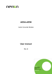
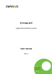
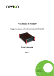
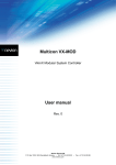
1
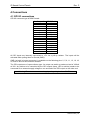
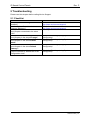
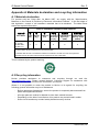
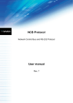
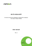
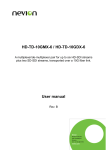
CP44-MEC+ CP16-LCD+ CP-MDP-BW+ CP-MDP-CL+ VikinX IP-based Control Panels for Multicon User manual Rev. P Nevion Nordre Kullerød 1 3241 Sandefjord Norway Tel: +47 33 48 99 99 nevion.com IP Based Control Panels Rev. P Nevion Support Nevion Europe Nevion USA P.O. Box 1020 3204 Sandefjord, Norway Support phone 1: +47 33 48 99 97 Support phone 2: +47 90 60 99 99 1600 Emerson Avenue Oxnard, CA 93033, USA Toll free North America: (866) 515-0811 Outside North America: +1 (805) 247-8560 E-mail: [email protected] See http://www.nevion.com/support/ for service hours for customer support globally. Revision history Current revision of this document is the uppermost in the table below. Rev. Repl. Date Sign P 13 2015-05-11 MB 13 12 11 10 12 11 10 9 2012-04-19 2009-08-17 2008-10-10 2007-10-23 JGS JIH NBS 9 8 2007-03-30 8 7 7 6 08/05/06 16/11/04 6 5 29/06/04 5 4 3 2 1 0 4 3 2 1 0 - 26/03/04 19/02/04 06/01/04 19/12/03 05/12/03 25/11/03 Change description Cover page update; DoC removed; no other changes to content Removed EPC information Updated for Multicon New format, updated illustrations, etc. New front page. Added Materials Declaration and EFUP; updated EC Declaration of Conformity. Added Software note at the end of this document. Added information about GPI pinout. (Chapter 3.5). Redesigned document, added Control Panel Configurator features Added warranty description. Corrected DIP information table. Updated DIP information. Added more configuration options. Updated with more programming facilities. Initial Revision nevion.com | 2 IP Based Control Panels Rev. P Contents Revision history ..................................................................................................................... 2 Definitions, Acronyms and Abbreviations............................................................................... 4 1 Product overview ................................................................................................................ 5 1.1 Control Panel Features .................................................................................................... 5 2 Specifications ..................................................................................................................... 7 2.1 Front view ........................................................................................................................ 7 2.2 Rear view ........................................................................................................................ 7 2.3 Power connection ............................................................................................................ 8 3 Configuration ...................................................................................................................... 9 3.1 Router Control Interface .................................................................................................. 9 3.2 Ethernet setup ................................................................................................................11 3.3 Panel Group Setup .........................................................................................................12 3.4 DIP switches on the panel ..............................................................................................12 3.4.1 Upper DIP switch block (SW1).....................................................................................13 3.4.2 Lower DIP switch block (SW2).....................................................................................13 3.5 LED Status .....................................................................................................................13 4 Connections ......................................................................................................................14 4.1 GPI I/O connections .......................................................................................................14 5 Troubleshooting.................................................................................................................15 5.1 Checklist.........................................................................................................................15 General environmental requirements for Nevion equipment .................................................16 Important notes regarding Software in the VikinX Modular router family range .....................17 Product Warranty .................................................................................................................18 Appendix A Materials declaration and recycling information .................................................19 A.1 Materials declaration ......................................................................................................19 A.2 Recycling information .....................................................................................................19 nevion.com | 3 IP Based Control Panels Rev. P Definitions, Acronyms and Abbreviations CSD SCK CP-16LCD CP-44MEC CP-MDP Multicon Syscon ETH-CON IP Customized Surface Design Software Configurable Keys Control panel with 16 LCD buttons Control panel with 44 illuminated buttons Master Display panel with 64 illuminated buttons New system controller for VikinX routers and element manager for Flashlink cards Legacy system controller for VikinX Modular router series Ethernet based system controller in N-Box housing Address in Internet Protocol (IP), used in TCP/IP connections nevion.com | 4 IP Based Control Panels Rev. P 1 Product overview Important firmware notice: CP-44MEC+, CP-16LCD+, CP-MDP-BW+ and CP-MDP-CL+ products comes pre-installed with firmware (version 2.X) for Multicon and cannot be used with legacy ETH-CON and Syscon products. It is possible to downgrade these products with firmware (version 1.X) for use with ETH-CON and Syscon. CP-44MEC, CP-16LCD, CP-MDP-BW and CP-MDP-CL products comes preinstalled with firmware (version 1.X) for use with ETH-CON and Syscon. It is possible to upgrade these products with firmware (version 2.X) for Multicon. Nevion’s IP-based Control Panel series includes advanced programmable control panels, for control of Nevion VikinX routers and Flashlink cards. The Multicon controller also gives you possibility to control 3rd party router systems from these panels. All buttons on the control panels are configurable. The configuration is done from a Windows computer with Nevion Configurator installed. The IP-based Control Panel series includes three different panel types: CP-44MEC+, CP16LCD+ and CP-MDP+. In addition, CP-44MEC+ and CP-16LCD+ may be combined to form larger control panels, by using the Expandable Panel Concept (EPC). The CP-44MEC+ is a 1RU programmable control panel, offering 44 buttons, with tri-color illumination and 16 GPI (I/O). The panel communicates with the router via TCP/IP panel bus. The CP-16LCD+ is a 1RU programmable control panel, offering 16 LCD buttons, with tricolor illumination and 16 GPI (I/O). The panel communicates with the router via TCP/IP panel bus. The CP-MDP+ is a 2RU programmable control panel, offering 64 buttons, with tri-color illumination and 16 GPI (I/O). The panel communicates with the router via TCP/IP panel bus. Further, the panel offers a 320x240 QVGA display, either color or B/W. 1.1 Control Panel Features The control panels support the Software Configurable Keys concept (SCK), which means that the control panels are fully programmable. Each button may be separately configured with all the supported features. Virtual Router Functions Map your physical levels into one virtual level. A virtual router may only include routers that are physically connected to your system/application. Standard functions implemented (Src, Dest, SrcToDest and Level selectors). Router Functions Standard router functions are implemented (Src, Dest and SrcToDest). Salvo Standard salvo execution on each button may be configured. The salvo status is indicated by button color. Category This option is a quick way to select virtual sources and/or destinations. GPI I/O nevion.com | 5 IP Based Control Panels Rev. P A button can be configured to be a GPI Output trigger. A GPI Input can also trigger a switch command, or a salvo. Layout features Support features like button copy, button move and clear button function. Special Functions Take Panel Enable Audio/Video Toggle X-point Lock/Unlock Additional special functions available on CP-44MEC: Take On/Off Additional special functions available on CP-16LCD: Take On/Off Additional special functions available on CP-MDP: Source or Destination mode selection Scroll Up/Down Clear Preset Previous Source Menu functions (Display, Enter, Up, Down, Clear) Numeric Keypad (0 – 9) and numeric backspace Required buttons, that must be configured, are: - Panel Enable - Take nevion.com | 6 IP Based Control Panels Rev. P 2 Specifications 2.1 Front view Figure 1: CP-44MEC+ front view Figure 2: CP-16LCD+ front view Figure 3: CP-MDP+ front view 2.2 Rear view Power RS-232/RS-422 Not used Configuration switches Ethernet Status LEDs GPI I/O Figure 4: CP-44MEC+ and CP-16LCD+ rear view Power RS-232/RS-422 Ethernet Status LEDs Not used GPI I/O Configuration switches Figure 5: CP-MDP+ rear view Note that in Figure 4 and Figure 5 the two Status LEDs are not shown on the drawings. nevion.com | 7 IP Based Control Panels Rev. P 2.3 Power connection Do not connect mains to the power supply before connecting the power supply to the panel. Connect the DB9 female connector from the desktop power supply to the main unit. Tighten the screws to assure a proper contact. To connect mains to the desktop power supply you need a mains cord with IEC 320 connector. The VikinX IP-based Control Panels are normally delivered with the desktop power model AC ±5V/35W. Upon customer request the panels can also be delivered with DC ±5V/30W, which may be fed by a 36 – 72 VDC mains power source. A Frame mounted power supply solution is also available. Please refer to the latest VikinX Product Catalogue for power supply types, or call Nevion for this information. Current draw by the panels, without any load on the GPI output: CP-44MEC CP-16LCD CP-MDP +5V / 1.2A +5V / 1.1A +5V / 1.7A The following pin-out is used on the DB9 male power connector: Pin# 1 and 9 Pin# 2 and 5 0V / GND +5V. nevion.com | 8 IP Based Control Panels Rev. P 3 Configuration Use the accompanying software package; Nevion Configurator when configuring communications setting, button functions, etc. Each subnet, or site, must have a PC with Nevion Configurator installed, in order to configure your systems. When this software package has been installed on your PC, just start the program identified by the icon; Figure 6: Nevion Configurator startup icon Note that Nevion Configurator has to run with Administrator rights on Windows Vista operating systems. Follow the instructions documented in the User Manual for Nevion Configurator in order to configure your CP-44MEC+, CP-16LCD+ and/or CP-MDP+. Please read the chapters hereunder, as the information provided forms a useful background before configuring your system. 3.1 Router Control Interface The interface between each unit is standard Ethernet bus. All router system controllers and Control Panels are connected together through a standard Ethernet Hub/Switch. The connections follow the standard set by the IEEE 802.3 10/100BaseTX specification. The applied cables should be CAT-5 / CAT-5E standard, or better. The router control interface may be different depending on the type of router you have in your system. VikinX Modular Router – Multicon VX-MOD The VikinX Modular Router includes a built-in system controller (Multicon VX-MOD). The system controller is also used to provide an interface between control panel and router system. Multicon VX-MOD can also control up to 8 VikinX Sublime/Compact routers. nevion.com | 9 IP Based Control Panels Rev. P Figure 7: Typical system setup with Multicon VX-MOD VikinX Sublime/Compact – Multicon VX-SLC Multicon VX-SLC is a system controller for up to 32 VikinX Sublime/Compact routers. It also works as an Ethernet gateway between IP-based CPs and VikinX Sublime/Compact routers interconnected via the NCB bus. Note that the Multicon N-BOX product consists of a Multicon VX-SLC card delivered in a N-BOX housing and Multicon FR-2RU is a Multicon VX-SLC card delivered in a Flashlink frame. Figure 8: Typical system setup with Multicon VX-SLC Note that the NCB must be either looped, or as in the figure above, terminated at both ends. Flashlink – Multicon GYDA Multicon GYDA is an element manager for Flashlink which also includes a system controller for up to 8 VikinX Sublime/Compact routers. nevion.com | 10 IP Based Control Panels Rev. P Figure 9: Typical system setup with Multicon GYDA 3.2 Ethernet setup It is recommended to connect the router system and control panels on a separate Ethernet to prevent any interference from other Ethernet devices and to keep the load on the network to a minimum. This will give the best system performance. Every unit must have a unique IP address on the Ethernet LAN. The drawing below shows a typical system setup: Figure 10: Ethernet setup Ethernet setup must be done with the Nevion Configurator software package, which is supplied together with any of the CPs or routers. If using managed Ethernet switch; set all ports to panels and routers to auto negotiation. nevion.com | 11 IP Based Control Panels Rev. P 3.3 Panel Group Setup On the back of each control panel there is a DIP-Switch block used for putting a control panel into panel groups. Panel group is used for mapping a control panel configuration file to a panel. If several control panels should have the same functionality, just put them into the same panel group. Every changes made to the control panel configuration file will be applied to all the control panels in the same panel group. You may also put all control panels into unique groups and apply the same configuration file the each group. You may only include same type of control panels in the same panel group! The drawing below shows a typical system setup: Figure 11: Panel Group setup 3.4 DIP switches on the panel The dipswitches on the rear of the panel are used to configure settings that are supposed to be fixed during operation of the panel. Look for the OPEN, or ON text on the switch block, to verify correct position of the dipswitches. The ON/OFF silkscreen text on the panel is NOT valid for the Piano Type switches. The figure below shows both types of dipswitch blocks that may be used on this panel. Piano Type switch Straight Type switch Figure 12: Dipswitch blocks nevion.com | 12 IP Based Control Panels Rev. P The figure above may not show the dipswitches in their default position. 3.4.1 Upper DIP switch block (SW1) Switch # 1 2 3 4 5 6 7 8 CLOSED, or ON (Default) To be defined. To be defined. To be defined. To be defined. To be defined. To be defined. Debug information on RS-232 port Not used OPEN To be defined. To be defined. To be defined. To be defined. To be defined. Not used RS-232 port silent / RS-422 port available Not used 3.4.2 Lower DIP switch block (SW2) The lower dipswitch block is used to assign the control panel to a Panel Group. A Panel Group contains one or more panels with the same configuration. See Chapter 3.3 for further information. The Panel Group is selected according to the following table, where OPEN and CLOSED are described as follows: 0 = OPEN 1 = CLOSED, or ON Switch # 1 0 0 0 0 0 0 0 0 0 : : 0 0 : : 1 1 2 0 0 0 0 0 0 0 0 0 : : 0 0 : : 1 1 3 0 0 0 0 0 0 0 0 0 : : 1 1 : : 1 1 4 0 0 0 0 0 0 0 0 0 : : 0 0 : : 1 1 5 0 0 0 0 0 0 0 0 1 : : 0 0 : : 1 1 6 0 0 0 0 1 1 1 1 0 : : 0 0 : : 1 1 7 0 0 1 1 0 0 1 1 0 : : 0 0 : : 1 1 8 0 1 0 1 0 1 0 1 0 : : 0 1 : : 0 1 Panel Group 000 001 002 003 004 005 006 007 008 : : 032 033 : : 254 255 3.5 LED Status The lamps on the rear side of the panel are displaying status. See the following table for description of the lamps. LED Description LED A Shows if LAN is connected LED B N/A (Test purpose) nevion.com | 13 IP Based Control Panels Rev. P 4 Connections 4.1 GPI I/O connections GPI I/O connector type is DB25 female. In-/Output # 1 2 3 4 5 6 7 8 9 10 11 12 13 14 15 16 DB25 Pin # 12 24 23 10 9 21 20 7 6 18 17 4 3 15 14 1 All GPI inputs are internally connected to +5V via a pull-up resistor. The inputs will be activated when pulling them to Ground (GND). GND (on both in-/output connector) is available on the following pins: 2, 5, 8, 11, 13, 16, 19, 22, and 25 and on the connector chassis. The GPI outputs are of open collector type. An output can switch a maximum load of 100mA at 30V. Any device to be controlled by the GPI outputs (lamp, LED or similar) needs to be connected to an external supply voltage on one end and to the GPI output on the other end. Warning! Do not connect external supply voltages higher than 30V DC. nevion.com | 14 IP Based Control Panels Rev. P 5 Troubleshooting Please read this chapter before calling Nevion Support. 5.1 Checklist Question Is the latest Nevion Configurator installed? Has the System Controller the latest firmware (Multicon)? Are System Controller, Control Panels and computer connected to the same LAN? Are System Controller, Control Panels and computer in the same IP range? Are System Controller, Control Panels and computer in the same subnet mask? Are System Controller, Control Panels and computer in the same Default Gateway? Does the control panel have the correct system controller IP address set in the configuration view? Actions to follow Check the website: http://www.nevion.com/support/ Check the website: http://www.nevion.com/support/ Check your switch / hub Check the IP settings (using System Configurator). Check the IP settings (using System Configurator). Check the IP settings (using System Configurator). Check the IP settings (using System Configurator). nevion.com | 15 IP Based Control Panels Rev. P General environmental requirements for Nevion equipment 1. 2. - The equipment will meet the guaranteed performance specification under the following environmental conditions: Operating room temperature range: 0°C to 45°C Operating relative humidity range: <90% (non-condensing) The equipment will operate without damage under the following environmental conditions: Temperature range: -10°C to 50°C Relative humidity range: <95% (non-condensing) nevion.com | 16 IP Based Control Panels Rev. P Important notes regarding Software in the VikinX Modular router family range This product utilizes software components that are licensed with open source licenses. The source code for these components and our modifications are available from: http://labs.nevion.com/open-source/ You may also send Nevion a recordable CD and a self-addressed envelope, and we will burn the contents of http://labs.nevion.com/open-source/ to your CD and send it back to you. This offer is valid for 3 years after purchase of this product. nevion.com | 17 IP Based Control Panels Rev. P Product Warranty The warranty terms and conditions for the product(s) covered by this manual follow the General Sales Conditions by Nevion, which are available on the company web site: www.nevion.com nevion.com | 18 IP Based Control Panels Rev. P Appendix A Materials declaration and recycling information A.1 Materials declaration For product sold into China after 1st March 2007, we comply with the “Administrative Measure on the Control of Pollution by Electronic Information Products”. In the first stage of this legislation, content of six hazardous materials has to be declared. The table below shows the required information. Toxic or hazardous substances and elements 組成名稱 Part Name 鉛 汞 镉 六价铬 多溴联苯 多溴二苯醚 Lead Mercury Cadmium Hexavalent Polybrominated Polybrominated (Pb) (Hg) (Cd) Chromium biphenyls diphenyl ethers (Cr(VI)) (PBB) (PBDE) CP-44MEC+ CP-16LCD+ O O O O O O CP-MDP-BW+ CP-MDP-CL+ O: Indicates that this toxic or hazardous substance contained in all of the homogeneous materials for this part is below the limit requirement in SJ/T11363-2006. X: Indicates that this toxic or hazardous substance contained in at least one of the homogeneous materials used for this part is above the limit requirement in SJ/T11363-2006. This is indicated by the product marking: A.2 Recycling information Nevion provides assistance to customers and recyclers through our web site http://www.nevion.com/. Please contact Nevion’s Customer Support for assistance with recycling if this site does not show the information you require. Where it is not possible to return the product to Nevion or its agents for recycling, the following general information may be of assistance: Before attempting disassembly, ensure the product is completely disconnected from power and signal connections. All major parts are marked or labeled to show their material content. Depending on the date of manufacture, this product may contain lead in solder. Some circuit boards may contain battery-backed memory devices. nevion.com | 19