1
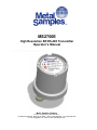
MS2700E High Resolution ER RS-485 Transmitter Operator’s Manual Metal Samples Company A Division of Alabama Specialty Products, Inc. 152 Metal Samples Rd., Munford, AL 36268 Phone: (256) 358-4202 Fax: (256) 358-4515 E-mail: [email protected] Internet: www.metalsamples.com . Table of Contents I. Introduction .............................................................................................................................................. 1 A. General Description ................................................................................................................... 1 B. Principles of Operation .............................................................................................................. 1 C. Technical Specifications ............................................................................................................. 3 II. Installation and Operation ....................................................................................................................... 4 A. Receiving the MS2700E transmitter .......................................................................................... 4 B. Installation ................................................................................................................................. 4 1. Physical Mounting and Probe Connection ................................................................... 4 a. Direct‐Probe Mounting ...................................................................................... 4 b. Remote Mounting .............................................................................................. 5 2. Power and Data Connections ....................................................................................... 5 a. Making Connections ........................................................................................ 5 b. Grounding ......................................................................................................... 6 c. Safe Area Installation ........................................................................................ 7 d. Hazardous Area Installation............................................................................... 7 3. Setup and Operation ....................................................................................................... 9 a. Probe Settings ................................................................................................. 9 b. RS‐485 Communication Settings ................................................................... 10 i. Baud Rate and Default Communication Parameters ............................. 11 ii. Device Address ...................................................................................... 11 iii. Communication Protocols ..................................................................... 11 iv. Termination Resistor ............................................................................. 11 v. Data Registers ....................................................................................... 11 c. Calibration and Testing ................................................................................. 12 i. Calibration ............................................................................................... 12 ii. Testing output zero and span ................................................................. 12 iii. Testing the MS2700E transmitter with the Meter Prover ....................... 12 d. Interpreting Data ........................................................................................... 13 i. Metal Loss ................................................................................................ 13 ii. Calculating Corrosion Rate ....................................................................... 14 e. Commissioning .............................................................................................. 15 C. Maintenance ............................................................................................................................ 15 D. Troubleshooting ....................................................................................................................... 16 III. Service and Warranty Information ....................................................................................................... 17 A. Warranty ................................................................................................................................... 17 B. Obtaining Service and Returning the Instrument for Repair .................................................... 17 C. Instrument Repair Form ........................................................................................................... 18 Appendix A ‐ Drawings ............................................................................................................................... 19 Control Drawing (Hazardous Area Wiring Diagram) ..................................................................... 20 Safe Area Wiring Diagram ............................................................................................................. 21 Appendix B – Revision History ................................................................................................................... 22 . I. Introduction A. General Description The model MS2700E transmitter is a high resolution instrument designed to measure and transmit corrosion (metal loss) data from an Electrical Resistance (ER) probe to a plant control system or other recording device. The MS2700E transmitter utilizes RS‐485 communication which allows multiple units to be daisy‐chained, simplifying installation and reducing associated costs. The use of the RS‐485 protocol also allows the transmitter to be placed great distances from the control system or recorder while maintaining good noise rejection. Practical distances can be up to 4000 feet. Additionally, the MS2700E transmitter offers user‐selectable RTU or ASCII communication protocols making it highly versatile. The MS2700E transmitter is compatible with all types of Metal Samples ER probes, as well as any standard ER probe from other manufacturers. Unlike competitors’ products, the MS2700E transmitter does not require factory modification to accommodate different probe types. The probe type can be easily changed at any time using the on‐board probe selection switches (see page 9.) The MS2700E transmitter is available as direct‐mount (standard) or remote‐mount. The direct‐mount version is mounted directly to the ER probe. This option offers the simplest installation and minimizes noise problems. The remote‐mount option allows the MS2700E transmitter to be mounted independently from (but in close proximity to) the ER probe. It is then connected to the probe via a short probe cable. (See pages 5 and 6 for mounting diagrams and specifications.) B. Principles of Operation The MS2700E transmitter operates on the Electrical Resistance (ER) technique and is used in conjunction with an ER probe. The ER probe utilizes a resistive sensing element manufactured from the material of interest (or a close approximation) which is exposed to a corroding environment. This is called the Exposed or Corroding Element. The resistance of the Exposed Element is directly related to its thickness, so as the element corrodes the resulting loss of metal causes a proportional increase in the element’s resistance. The probe also contains an internal Reference Element which is used to compensate for the influences of temperature on the Exposed Element. The MS2700E transmitter is designed to work with any standard ER probe, but it is recommended that Cylindrical and Large Flush type probes be used to ensure optimum performance. Their physical design places the Reference Element in closer proximity to the Exposed Element compared to other probe types, providing more effective temperature compensation and thus reducing the effects of thermal noise. Because they are designed to corrode, ER probes are sacrificial in nature. Each ER probe will have a finite life that is based on the element thickness. ER probes are available in a number of geometries and thicknesses designed to suit a wide variety of applications. Table 1 lists the common ER element options available from Metal Samples and the effective life of each. 1 Element Type Tubular Loop Wire Loop Compatibility Compatible Compatible Flush (Small) Compatible Cylindrical Preferred Flush (Large) Preferred Thickness Probe Life (Span) 4 2 8 4 40 10 80 20 4 8 20 10 20 50 5 10 20 40 2 4 10 5 10 25 2.5 5 10 20 Table 1. Standard ER Probe Elements The MS2700E transmitter measures an ER probe utilizing a high‐resolution, 16‐bit measurement. This allows the unit to detect much smaller amounts of metal loss, thus responding faster to corrosion events and upsets. At 16‐bit resolution the MS2700E transmitter can measure metal loss amounts as small as 0.0015% of the probe life. Metal loss readings taken by the MS2700E transmitter are output as a digital RS‐485 signal which can be fed into a plant control system or other recording devices. The Metal Loss is represented by a 16‐bit digital value between 0 and 65535, where: 0 = 0 mils (0% Metal Loss) 65535 = Probe Life* in mils (or 100% Metal Loss) *The Probe Life (or Span) of the probe being used (see table 1 above.) The Metal Loss data can be used to calculate the corrosion rate between any periods of interest. This is covered in more detail on pages 13 and 14. More information on ER probes, their theory, selection, and use can be found on our web site at http://www.alspi.com/erintro.htm. 2 C. Technical Specifications Model MS2700E High Resolution ER RS‐485 Modbus Transmitter Physical Data Instrument Weight: Total Weight w/ Accessories: Instrument Dimensions: 3.70 lb. (1.68 Kg) 5.76 lb. (2.61 Kg) 6.0"H x 4.0"Dia (15.25cm H x 10.16cm Dia) Operating Temperature: Storage Temperature: Environmental Rating: Enclosure Material: Mounting Specifications: 4.0” Dia (10.16cm) 6.0”H (15.25cm) ‐4° to 158°F (‐20° to 70°C) ‐40° to 176°F (‐40° to 80°C) IP66 Figure 1. Overall Dimensions 316 Stainless Steel Direct probe mount (standard) May be pole mounted using optional hardware (Up to a 2.5” (6.35cm) Dia. pole) Performance Data Measurement Type: Range: Resolution: Cycle Time: ER measurement using any standard ER probe type (Wire Loop, Tube Loop, Cylindrical, Flush, Strip, etc.) 0‐100% of probe life 0.0015% of Probe Life (16‐bit) 75 Seconds Electrical Data Power Requirements: Maximum Probe Cable Distance: Output Specifications: 10 to 28 VDC 30 ft (9.1 m) RS‐485 Modbus, RTU or ASCII Protocol (Switch Selectable) 2400 / 4800 / 9600 / 19.2K Selectable Baud 32 Maximum Units (Addresses 1 to 32) Hazardous Location Certifications – Intrinsic Safety USA / Canada Conforms to ANSI/UL Std. 60079‐0, 60079‐11, 61010‐1 CAN/CSA Std. E66079‐0, E60079‐11 & CAN/CSA C22.2 No. 61010‐1 For Stand‐Alone Use For Multi‐Drop Use Class I, Zone0, AEx ia IIC T4 Ga Class I, Zone0, AEx ia IIB T4 Ga Zone 20, AEx ia IIIC T130° C Da Zone 20, AEx ia IIIB T130° C Da ‐20° C ≤ Ta ≤ +70° C ‐20° C ≤ Ta ≤ +70° C Europe and Worldwide (ATEX and IECEx) For Stand‐Alone Use For Multi‐Drop Use II 1 G Ex ia IIC T4 Ga II 1 G Ex ia IIB T4 Ga II 1 D Ex ia IIIC T130°C Da II 1 D Ex ia IIIB T130°C Da ‐ 20°C ≤ Ta ≤ + 70°C ‐ 20°C ≤ Ta ≤ + 70°C ATEX Certificate No: ITS14ATEX28092X IECEx Certificate No: IECEx ITS 14.0052X X ‐ see Special Conditions (page 7) Included Accessories 3’ (1M) Wiring Harness, Meter Prover, Operations Manual Optional Accessories Probe Extension Cable, Remote Mounting Hardware 3 II. Installation and Operation A. Receiving the MS2700E Transmitter Check the MS2700E Transmitter for any shipping damage when it is first received. When the unit is unpacked, verify that the following items are included: Transmitter Wiring Harness Meter Prover User’s Manual Probe Cable (optional, for remote‐mount only) Mounting Hardware (optional, for remote‐mount only) In the event of shipping damage, quantity shortage, or missing items, it is recommended that the event is documented immediately and that digital photographs are taken. Any shortages or missing items should be reported to Metal Samples immediately. In the event of shipping damage, a claim should be opened with the responsible carrier. B. Installation CAUTION: Using this product in any way other than that specified within this manual may impair the intrinsic safety protection. Installation of the MS2700E transmitter involves the following steps: 1. Physical Mounting 2. Electrical Connection 3. Setup and Programming 1. Physical Mounting and Probe Connection When selecting a location to mount the MS2700E transmitter it is important to consider the surrounding environment. To ensure proper operation: Do not mount the transmitter in a location that exceeds its operating temperature. Avoid mounting the transmitter near sources of strong electrical noise. Ensure that there is sufficient clearance for installation and to open the transmitter cover afterwards. a. Direct‐Probe Mounting The MS2700E transmitter is designed for direct‐probe mounting which eliminates the need for additional hardware and transmitter‐to‐probe cabling. This greatly simplifies installation, reduces costs, and minimizes electrical noise that can be coupled onto probe cabling from nearby electrical equipment. Before mounting the MS2700E transmitter, first ensure that the probe is installed properly and securely. During installation it is important that you do not apply excessive force on the probe or seals, as doing so could break the seal and result in system leakage. 4 To mount the MS2700E transmitter: 1. Align the keyways of the transmitter and probe connectors. 2. Insert the transmitter connector plug fully into the probe connector receptacle. 3. Secure the transmitter to the top of the probe by tightening the coupling nut. NOTE: Hand‐tight is sufficient. Do not over‐tighten the coupling nut. NOTE: Never force the connectors to mate. If there is resistance, stop and check for bent pins on the probe and for foreign material in the female sockets of the transmitter connector. Gently straighten any bent pins and clear any foreign material that may be found. Align Key Insert Connector 1 2 Tighten Coupling Nut 3 Figure 2. Direct Mount Installation b. Remote Mounting When it is not practical to direct‐probe mount the MS2700E transmitter, the unit can be remote mounted instead. In this case the instrument is mounted to a separate mounting pole using the optional Remote Mounting Hardware Kit. The transmitter is then connected to the ER probe via the optional probe extension cable. When possible, the transmitter should be mounted within 10’ (3m) of the probe to keep the probe cabling short and minimize signal degradation. 2. Power and Data Connections a. Making Connections The RS‐485 connections are made via the external 6‐pin circular connector CN1 as shown in Figure 3. This hermetically sealed connector prevents moisture ingress and eliminates the need for internal wiring by an operator, thus reducing the risk of physical damage to the circuit board. 5 Connector CN1 (Power and Data) Figure 3. RS‐485 Connector To facilitate wiring, a three foot (1 meter) wiring harness is provided. This wiring harness connects directly to the 6‐pin connector, and extends to a nearby junction box (not included) to make the necessary power and data wiring connections from the control (DCS/PLC) system. Wiring Harness Junction Box (Not Included) Figure 4. MS2700E Transmitter Wiring Harness NOTE: Do not connect cable shielding to the Transmitter. The shield must remain floating at the Transmitter. The maximum permissible length of the field wiring between the MS2700E transmitter and the control system is determined by the control system supply voltage, the electrical resistance of the cable and the load of the control system input. If the Transmitter is to be installed in a safe area, refer to section c. Safe Area Installation for details. If the Transmitter is to be installed in a hazardous area, refer to section d. Hazardous Area Installation. b. Grounding The MS2700E transmitter enclosure is grounded internally through the wiring harness, but an additional, external grounding terminal is provided as well. The enclosure should be grounded properly using the external grounding terminal to ensure safe operation. 6 c. Safe Area Installation The MS2700E transmitter is approved for use in hazardous areas, but can be used in non‐hazardous areas as well. For basic safe area wiring information refer to the circuit diagram shown on page 21. CAUTION: When used in non‐hazardous areas, equipment must be supplied with a pre‐approved power supply unit or approved equipment which meets the entity parameters shown below. The pre‐approved equipment must be certified to the electrical safety standards for equipment in ordinary locations (for example, EN/IEC/CSA UL 61010‐1 or EN/IEC/CSA UL 60950‐1). Failure to meet these requirements will void the intrinsic safety certification of the equipment and prohibit its future use in hazardous areas. d. Hazardous Area Installation CAUTION: This section provides general guidelines for hazardous area wiring. However, regardless of anything stated here, the MS2700E transmitter must be installed in full compliance with the control drawing located on page 20 and all of the local area requirements. CAUTION: When used in Hazardous areas, equipment must be supplied with a pre‐approved power supply unit or approved equipment via a certified intrinsically safe barrier or a galvanically isolated barrier) with the following entity parameters. Input supply terminal Connector CN1 pins A & B (J2 on PCB): Ui = 23 Vdc Ii = 88.2 mA Pi = 0.52 W Ci = 0 Li = 0 RS-485 channel at each line Connector CN1 pins D & E (J9 on PCB): Ui = 3.7 Vdc Ii = 225 mA Pi = 0.206 W Probe connector Connector CN2 (J1 on PCB): Uo = 5 V Io = 503 mA Po = 0.7 W RS-485 channel CN1 and connector CN2 (Combined) Ci = 68uF Li = 0 Co = 32uF Lo = 0.14 mH Input supply terminal, RS-485 terminal and connector CN2 (combined) Ui = 23 Vdc Ii = 538 mA Pi = 0.7 W Ci = 68uF Li = 0 Co = 32uF Lo = 0.14 mH Special Conditions 1. Probe dielectric rating < 500V r.m.s. Do not exceed. 2. Networked (“daisy‐chained”) arrangement not for use in Group IIC/IIIC environment. 3. The maximum external capacitance ‘Co’ that can be connected between RS‐485 terminals (CN1) and probe terminals (CN2) is 32uF. The maximum external Inductance ‘Lo’ that can be connected between RS‐485 terminals (CN1) and probe terminals (CN2) is 0.14 mH. 7 Whenever an electrically driven sensor or measuring device is used in a potentially explosive environment the measuring system must be installed in such a way that electrical energy is either effectively isolated from the explosive environment (via explosive‐proof containers, cable conduits, etc.) or the amount of electrical energy produced in the hazardous area must be limited to an intrinsically safe level. Limiting electrical energy is the most practical method of protecting the MS2700E transmitter when it is installed in a hazardous area. In the MS2700E transmitter, electrical energy limits are maintained by the use of appropriate safety barriers installed in the power and data wiring. The safety barriers must be located in the safe area near the boundary between the safe and hazardous areas. The safety barrier will repeat the signal current generated by the Transmitter and will relay the signal to the data receiving station. Caution: When a safety barrier is used with the MS2700E transmitter, the transmitter wiring connections must be connected to the safety barrier’s hazardous area terminals. All other connections must be made to the barrier’s safe area terminals. The type of repeater safety barriers used with the MS2700E transmitter depends on the specific classification of the hazardous environment in question. However, the entity parameters must match those of the MS2700E transmitter. CAUTION: For hazardous area installations, the maximum inductance and capacitance of the field wiring between the safety barrier and the transmitter cannot exceed the entity parameters of the selected barrier. 8 3. Setup and Operation a. Probe Settings The probe selection switches are located on the top left corner of the main board as illustrated in Figure 5 below. These switches are used to set the ER probe type. They also allow the instrument to be placed into several test modes which output fixed values, allowing verification of the output signal. Table 2 gives the switch settings for each probe type and the various test modes. Probe Cable Connector Switch 1 ‐ Probe Selection Switch (See Table 2 below) Switch 2 ‐ RS‐485 Configuration Switches (See Table 3 below) Power Connector (J2) Data Connector (J9) Figure 5. Connector and Switch Details Setting Wire Loop Operating Positions Switch 1 Test Positions 4 On (↑) On (↑) Off (↓) On (↑) Off (↓) On (↑) Off (↓) Off (↓) Off (↓) On (↑) Off (↓) Zero Output (0) On (↑) On (↑) Off (↓) Off (↓) Maximum Output (65535) Off (↓) On (↑) Off (↓) Off (↓) Full Scale Sweep On (↑) Off (↓) Off (↓) Off (↓) Tube Loop/Flush * Table 2. Probe Switch Settings *Cylindrical probe setting is illustrated. 9 Position 2 3 Off (↓) Cylindrical 1 b. RS‐485 Communication Settings The RS‐485 configuration switches are located on the top right corner of the main board as illustrated in Figure 5. These are used to set the instrument address, baud rate, communication protocol, and to enable the termination resistor. Table 3 gives the switch settings for each of these parameters, and they are explained in more detail below. Device Position Address 3 4 5 6 7 Off (↓) Off (↓) Off (↓) Off (↓) Off (↓) 1 On (↑) Off (↓) Off (↓) Off (↓) Off (↓) 2 Off (↓) On (↑) Off (↓) Off (↓) Off (↓) 3 On (↑) On (↑) Off (↓) Off (↓) Off (↓) 4 Switch 2 Off (↓) Off (↓) On (↑) Off (↓) Off (↓) 5 On (↑) Off (↓) On (↑) Off (↓) Off (↓) Position 6 Baud Rate Off (↓) On (↑) On (↑) Off (↓) Off (↓) 1 2 7 On (↑) On (↑) On (↑) On (↑) On (↑) Off (↓) Off (↓) 2400 8 Off (↓) On (↑) Off (↓) Off (↓) Off (↓) On (↑) Off (↓) 4800 9 On (↑) Off (↓) On (↑) Off (↓) Off (↓) On (↑) Off (↓) 9600 10 Off (↓) Off (↓) Off (↓) On (↑) Off (↓) On (↑) Off (↓) 19200 11 On (↑) On (↑) Off (↓) On (↑) Off (↓) 12 Off (↓) Off (↓) On (↑) On (↑) Off (↓) Position 13 Communication Protocol On (↑) Off (↓) On (↑) On (↑) Off (↓) 8 14 On (↑) Off (↓) On (↑) On (↑) On (↑) Off (↓) ASCII 15 Off (↓) On (↑) On (↑) On (↑) On (↑) Off (↓) RTU 16 Off (↓) Off (↓) Off (↓) Off (↓) On (↑) 17 On (↑) Off (↓) Off (↓) Off (↓) On (↑) Position 18 Termination Resistor Off (↓) On (↑) Off (↓) Off (↓) On (↑) 10 19 On (↑) On (↑) On (↑) Off (↓) Off (↓) On (↑) Active 20 Off (↓) Off (↓) Off (↓) On (↑) Off (↓) On (↑) Inactive 21 On (↑) Off (↓) On (↑) Off (↓) On (↑) 22 Off (↓) On (↑) On (↑) Off (↓) On (↑) Position 23 Reserved On (↑) On (↑) On (↑) Off (↓) On (↑) 9 24 Off (↓) Off (↓) Off (↓) On (↑) On (↑) Not Used N/A 25 On (↑) Off (↓) Off (↓) On (↑) On (↑) 26 Off (↓) On (↑) Off (↓) On (↑) On (↑) 27 On (↑) On (↑) Off (↓) On (↑) On (↑) 28 Off (↓) Off (↓) On (↑) On (↑) On (↑) 29 On (↑) Off (↓) On (↑) On (↑) On (↑) 30 Off (↓) On (↑) On (↑) On (↑) On (↑) 31 On (↑) On (↑) On (↑) On (↑) On (↑) 32 Table 3. RS‐485 Configuration Switch Settings 10 i. Baud Rate and Default Communication Parameters The default communication parameters for the MS2700E transmitter are provided in Table 4 below. If necessary, the baud rate can be changed using Positions 1 and 2 of Switch 2, as illustrated in Table 3. Parameter Value Baud Rate 19200 Data Bits 8 Parity Even Stop Bits 1 Table 4. Default Communication Parameters ii. Device Address Up to 32 MS2700E transmitters may be connected in a multi‐drop network (“daisy‐chained”) using a single cable run. However, each transmitter must be set to a unique device address to avoid conflicts. This is done using Positions 3 through 7 of Switch 2, as illustrated in Table 3. CAUTION: Be sure to observe the appropriate gas group rating listed on page 3 for stand‐alone or multi‐drop operation. iii. Communication Protocols The MS2700E transmitter offers user‐selectable RTU or ASCII communication protocols, giving the unit a broader range of compatibility. The communication protocol is set using Position 8 of Switch 2, as illustrated in Table 3. iv. Termination Resistor To ensure proper operation, the RS‐485 network must be terminated properly with a termination resistor. To facilitate this, each MS2700E transmitter has a built‐in 120 termination resistor that can be switched on or off using Position 10 of Switch 2. Once all units have been installed, be sure to enable the termination resistor of the last unit in the network. The termination resistors of all other transmitters should be turned off. v. Data Registers Table 5 lists the data registers of the MS2700E transmitter. No Register Address Description 1 40001 Device Status 2 40002 Device Address 3 40003 Baud Rate 4 40024 DAC Value 5 40026 Probe Switch Setting Table 5. Modbus Data Registers 11 c. Calibration and Testing i. Calibration The MS2700E transmitter is fully calibrated when shipped from the factory. The calibration settings are fixed to avoid accidental change which could result in erroneous data. No field calibration is required. However, it is important to test the unit upon installation, and during periodic maintenance inspections, to ensure the unit is operating properly. ii. Testing output zero and span The MS2700E transmitter Probe Selection Switches (page 9) offer three test settings that allow the unit to be placed into various diagnostic modes as follows: 1) Zero Output – Forces a digital output of 0. 2) Maximum Output – Forces a digital output of 65535. 3) Full Scale Sweep – Causes the output to continually cycle from 0 up to 65535. These test modes can be useful when troubleshooting communication problems between the transmitter and the DCS/PLC system. iii. Testing the MS2700E transmitter with the Meter Prover A Meter Prover is provided to allow routine checks of the MS2700E transmitter. The Meter Prover simulates a Wire Loop type probe at a fixed value. To test the unit with the Meter Prover: 1) Disconnect power. 2) Disconnect the MS2700E transmitter from the probe (or if the unit is remote‐mounted, disconnect the probe extension cable from the probe.) 3) Connect the Meter Prover to the probe connector stem (or to the probe extension cable if the MS2700E transmitter is remote‐mounted.) 4) Loosen the Enclosure Lock Screw. 5) Unthread and remove the transmitter cover. 6) Change the Probe Selection Switches to the Wire Loop position (see page 9.) 7) Reconnect power and allow the instrument to measure for several minutes to stabilize. 8) After several minutes observe the transmitter output. The output should closely match the value printed on the Meter Prover label. If the transmitter output matches the Meter Prover value, you may return the Probe Selection Switches to their previous setting and reconnect the MS2700E transmitter to the probe. If the transmitter output shows a significant difference compared to the Meter Prover value, further troubleshooting may be required. Refer to page 16 for troubleshooting or contact the factory for further assistance. Be sure to reinstall the enclosure cover and tighten the Lock Screw when putting the MS2700E transmitter back into service. 12 d. Interpreting Data i. Metal Loss The MS2700E transmitter measures the Metal Loss of an ER probe and converts that value to a digital 16‐bit RS‐485 Modbus output. This output is directly proportional to the cumulative Metal Loss of the ER probe at any given time. The overall span of the output is proportional to the life of the probe in use, so for DCS/PLC programming the RS‐485 Modbus output can be scaled as follows: 0 = 0 mils (0% Metal Loss) 65535 = Probe Life in mils (100% Metal Loss) The Probe Life can be found in Table 1 and is also listed on the Metal Samples probe tag (as the “Multiplier”.) Figure 6. Metal Samples Probe Tag RS‐485 Modbus Output Figure 7 illustrates the relationship between the digital output and Metal Loss. In this example a probe with a 10‐mil life is assumed. However, the X axis could be changed to represent any Probe Life. 65535 49151 32768 16384 0 0.0 2.5 5.0 7.5 New Probe Metal Loss (mils) 10.0 Probe Consumed Figure 7. Output Relationship As seen here, the transmitter output begins at 0 for a new probe (zero Metal Loss) and increases as the probe element corrodes, eventually reaching a maximum of 65535 when the probe sensing element has been completely consumed by corrosion (in this case, 10 mils of Metal Loss.) At this time the probe has reached its end‐of‐life and must be replaced. 13 ii. Calculating Corrosion Rate As explained previously, ER probes and instruments report Metal Loss. However, the value that is of ultimate interest is Corrosion Rate. The Corrosion Rate is essentially Metal Loss over time, so the Corrosion Rate can be calculated using the following formula: CorrosionRate mpy ∆MetalLoss mils ∆Time days 365 where: ∆MetalLoss(mils) is the difference between two Metal Loss readings Time(days) is the time difference between those two readings It is a common practice to program this formula into the control (DCS/PLC) system and have it calculate Corrosion Rate on a continual basis from the Metal Loss data. The challenge in doing this is selecting an appropriate time interval. Using an interval that is too short may give erratic results, while selecting an interval that is too long may give results that are insensitive to system upsets. The ideal time period depends on many factors, and will vary from system to system. It may take some trial and error to settle on the best time period for your installation. In some cases it may be necessary to review the raw Metal Loss data and manually apply the Corrosion Rate formula to periods of interest. For example, look at the graph below and see how much the calculated Corrosion Rate can vary depending on the time period used. Figure 8. Corrosion Rates calculated from Metal Loss data While each of the results is valid for the selected time period, the one of most interest is the value of 11.81 mpy which represents some type of system upset. When the Corrosion Rate is calculated automatically on a pre‐selected time period, there is no guarantee that the selected time period will always coincide with system upsets such as this. That is why manual review and interpretation of Metal Loss data is also helpful. 14 e. Commissioning Once the MS2700E transmitter has been installed, tested, and properly configured for the probe in use, it can then be closed and put into service. First, perform one last visual inspection to ensure that all electrical connections are secure and that the enclosure o‐ring is in place and is in good condition. Then thread the enclosure lid onto the base fully. Once the lid has been threaded into place, tighten the Lock Screw to prevent unauthorized tampering. Figure 9. Enclosure Lock Screw CAUTION: The Lock Screw on the instrument base must be tightened securely to prevent unauthorized personnel from opening the MS2700E transmitter, and ensure that the intrinsic safety is not violated. Only qualified personnel should be allowed to install, operate, and maintenance the MS2700E transmitter. C. Maintenance Once installed, the MS2700E transmitter requires little maintenance. However, it is important to verify the following items periodically to ensure continued safe operation. CAUTION: Before performing any tests or maintenance on the MS2700E transmitter, ensure that all hazardous area requirements are met. Inspection Item Inspect the enclosure o‐ring for any signs of damage. Replace as necessary. Inspect the probe connector o‐ring for any signs of damage. Replace as necessary. Inspect the external electrical connections for signs of corrosion, mechanical damage, or foreign matter that could cause damage or cause an electrical short. Clean as necessary. Ensure that the locking screw is in place and is secure. The MS2700E transmitter enclosure is made of corrosion‐resistant 316 stainless steel. However, it should still be checked periodically for any signs of corrosion. Check for any signs of moisture ingress within the enclosure. Contact Metal Samples for replacement parts or if instrument repair is necessary. 15 Frequency Annually Annually Annually Annually Annually Annually D. Troubleshooting If the MS2700E transmitter does not seem to perform as expected, check the following items: CAUTION: Before performing any tests or maintenance on the MS2700E transmitter, ensure that all hazardous area requirements are met. 1. Ensure that the probe is operational and is not completely corroded. This can be done in two ways. a. Test the probe with a portable ER meter if available. b. Test the probe with a portable resistance or continuity meter as follows: i. Connect one test lead to pin ‘A’ of the probes 6‐pin connector. ii. Measure continuity to each of the other pins. There should be continuity (low resistance) to each pin. NOTE: Continuity on each pin does not ensure that the probe is good. However, if you find an open circuit on any pins then it is almost certain that the probe is bad and should be replaced. 2. Ensure that the Probe Selection Switches are set correctly for the probe being used. Confirm the probe type and refer to Table 2 on page 9 to verify the appropriate switch settings. 3. Perform a visual inspection of the circuit boards to look for any signs of mechanical or electrical damage. 4. Ensure that all electrical cables and wiring are in good condition. 5. Ensure that all electrical contacts are secure and free of corrosion. 6. Ensure that there is adequate supply voltage at the power connector. 7. Verify that the supply voltage polarity is correct. 8. If there is insufficient supply voltage on the power connector, check the safety barrier (if applicable) for a blown fuse or any other failure. 9. Test the MS2700E transmitter using the supplied Meter Prover (see page 12.) These basic checks should indicate the source of any problem (probe, power supply, wiring, etc.). If it is determined that the MS2700E transmitter is malfunctioning, or if you need further assistance in troubleshooting, contact Metal Samples Technical Support. CAUTION: If the MS2700E transmitter shows any signs of damage, remove it from service immediately and consult the factory. 16 III. Service and Warranty Information A. Warranty Metal Samples warrants that any part of the model MS2700E transmitter and accessories which proves to be defective in material or workmanship within one year of the date of original shipment to Purchaser will be repaired or replaced, at Metal Samples option, free of charge. This warranty does not cover (1) probe assemblies, (2) items expendable in nature, or (3) items subject to damage from normal wear, misuse or abuse, or failure to follow use and care instructions. All damaged items are to be shipped at Purchaser’s expense to and from Metal Samples which shall have the right to final determination as to the existence and cause of a defect. The foregoing shall constitute the sole and exclusive remedy of any purchaser of Metal Samples products for breach of warranty and IS EXCLUSIVE AND IN LIEU OF ALL OTHER WARRANTIES, EXPRESSED, IMPLIED OR STATUTORY, INCLUDING THE IMPLIED WARRANTIES OR MERCHANTABILITY AND FITNESS. IN NO EVENT SHALL METAL SAMPLES BE LIABLE FOR SPECIAL OR CONSEQUENTIAL DAMAGES, OR FOR ANY DELAY IN THE PERFORMANCE OF THIS WARRANTY DUE TO CAUSES BEYOND ITS CONTROL. The technical information and suggestions contained herein are believed to be reliable, but they are not to be construed as warranties since conditions of use are beyond our control. B. Obtaining Service and Returning the Instrument for Repair If you experience problems with your instrument please contact the factory at 256‐358‐4202 and ask for customer support for instrumentation. Our customer support department will assist you in troubleshooting your instrument. Most issues can be resolved over the phone, but in some cases it may be necessary to return your instrument for further evaluation and repair. In this case, please obtain a Return Materials Authorization (RMA) number from the sales person or support technician. This RMA number will ensure that your instrument is routed to the correct department when it is received at the factory. After receipt of an RMA number you may pack your instrument for return. Be sure to pack your instrument in a sturdy box and to pad it sufficiently to avoid damage during transit. Also be sure to complete the “Instrument Repair Form” on the next page and include a copy with your repair. This will ensure that the repair department has sufficient information regarding the problems you are experiencing with your instrument, as well as the billing, contact, and return shipping details for the repair. Once you have obtained an RMA number, completed the “Instrument Repair Form”, and packed your instrument securely, please ship it prepaid to the following address: Metal Samples 152 Metal Samples Road Munford, AL 36268 ATTN: RMA# _ _ _ _ _ NOTE: Be sure to list your RMA number in the attention line (shown as blanks in the example above.) 17 C. Instrument Repair Form This form may be photocopied for use when returning an instrument to Metal Samples for repair. Please fill in all known information and enclose a copy of the completed form with the instrument. General Information Model Number RMA Number Serial Number Date of Purchase* *If known. Contact Information for Repair Contact Name Company Phone Number E‐mail Address Return Shipping Information Recipient Name* Return Address Company* *If different than above. Reason for Return. (Provide as much detail as possible. Attach additional pages if required.) Invoice Instructions (For non‐warranty repairs) Invoice me for the repair (Requires an open account with Metal samples.) Contact me for credit card information Reference PO# (For security purposes, do not list credit card information on this form..) 18 Appendix A: Drawings A. Wiring Diagrams Control Drawing (Hazardous Area Wiring Diagram) Safe Area Wiring Diagram 19 Appendix B: Revision History Revision Date Changes 0 8/15/2014 Initial Release A 9/17/2014 Revised entity parameters, hazardous area installation (control) drawing, and safe area installation drawing. B 10/9/14 Revised entity parameters and hazardous area installation (control) drawing. C 1/15/15 Separate gas group rating listed for Stand‐Alone and Multi‐Drop operation. Revised hazardous area installation (control) drawing. D 2/4/15 Revised entity parameters, hazardous area installation (control) drawings, and safe area installation drawing. 22