1
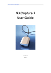
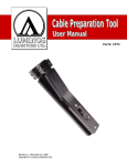
TSView User’s Manual
Contents
Instruction of the TSView
Chapter 1 Installation Recommendation
1.1
1.2
Operation system
Hardware requirement
Chapter 2 User instruction
2.1 Before the installation
2.1.1 Connecting the equipment
2.1.2. Installing TSView
2.2 Camera operation
2.2.1 Capture panel
2.2.2 Selecting the device type
2.2.3. Selecting the image resolution
2.2.4. Preview image
2.2.5. Setting data
2.2.6 Saving image
2.2.7 Capture、Start Video
2.3 Image measuring
2.3.1. ImagePocess panel
2.3.2. Selecting image
2.3.3 Measuring image
2.3.4 Histogram
2.3.5 Demonstration of Measurement Calibration
2.4 Image processing instruction
2.4. 1 ImageProcess panel
2.4.2 Image processing menu
Instruction of the TSView
TSView is the software products designed in connection with digital microscope
of the CMOS series and CCD series . With the functions of photo taking, image
measuring and
handling. The photo is in high clarity and checked against a
standard, in this way it improves its accuracy. Offered by the image handling function
the tools covers a range as follows: revolving tool, repair tool, sharpen/obscuring tool,
brightness tool, color adjusting tools so on and so forth. By utilizing the tools you can
improve the showing effect of the photo. TSView is in good interface and easy to be
operated simply to meet the customers’ need that one can measure the photo
immediately after taking it. Furthermore, we make a gradual development in
accordance with the customers’ need to improve our TSView software.
Chapter 1 Installation Recommendation
1.1 Operation system
TSView can work under Windows XP®, Windows Vista®, Windows 7® and the
system should be installed Directshow 9.0 components.
1.2 Hardware requirement
1.2.1 suggested use a higher disposition computer.
CPU: Intel Pentium 4-2.6G
RAM: 512 MB
HDD: 1GB free space
USB: USB2.0 interface (If the PC does not have, please add a USB2.0 interface
board).
1.2.2 The USB2.0 interface
Please confirm the computer equipped with USB2.0 interface and installed
correct driver before using the digital microscope. Recommendation use the
mainstream Inter chip product and install the newest camera actuation.
1
Chapter 2 User’s instruction
2.1 Before the installation
2.1.1. Connecting the equipment
Connecting the USB cable with both computer and digital device, and make the
both
devices keep connection.
2.1.2. Installing TSview
Open the disc, double click TSview, then click NEXT … till installation finished.
2.2 Camera operation
2.2.1 Capture panel
Startup TUCSEN from START→ PROGRAM→ TSview, see picture below :
2.2.2 Selecting the device type
In “Capture” panel, click “Detect Camera” button,
the software will identify Model and Spec. of digital
device automatically. And it will give the max.
resolution. See picture on the right side.
When you use the 0.3MP or 2.0MP Cameras,
you should click "detect Camera" button, then in the
pull-down box of resolution you should choose the
cameras. When you use UVC driver, you should
choose" USB Video Device. If you install the driver,
The 0.3MP camera should choose" USB 2.0 PC CAMERA",
choose " Vimicro USB2.0 UVC PC Camer
2
the 2.0 MP should
2
2.2.3. Selecting the image resolution
When the resolution, displayed by software automatically, can not meet your need,
you may click the drop-down menu of the “Resolution” to select the right pixel which
you need.
2.2.4. Preview image
You can start to preview image after finishing above work. Click the “Start
Preview” in the “Capture” panel, the software starts to work and the image will be
displayed on the window (See picture below). At that time, the original “Start Preview”
button will be changed to “Stop Preview”. When you plan to change device, set
resolution, close the program, click “Stop Preview” button first to stop preview of the
software, then start next operation.
2.2.5 Setting data
Under “Capture” panel, there’re buttons “Auto white
balance” “Area white balance” and “Advance…” (When
the button turns gray, it is useless). Click “Auto white
balance”, the software will make preview image white
balance automatically. Click “Area white balance”, the
operation is carried through imbibing a certain point on
preview image by hand, and this point is as datum mark
of white balance.
4
3
“Advance …” is setting image quality, color and light, etc. Click “Advance …”
button, the setting window will be displayed as the picture on the right. The window
has 3 selections “Color Adjust ” “Exposure” and “Other ”page layout:
1> The function of “White balance” in “Color
Adjust ”panel is the same as the one in “Capture”
panel, “Color Enhance” at right side is selected at
default state, it can enhance color, if cancel this option,
the preview rate will be expedited.
“R Gain”, “G Gain” and “B Gain” is operated by
adjusting white balance of Red, Green and Blue, 3
colors. In default, it is auto white balance. Through
regulating value of Gamma, Contrast and Saturation,
you can make the preview image perfect.
2> At “Exposure” page layout, you can set image
exposure time and gray target value (Gain). Auto
Exposure is in default, yon can set time value of auto
exposure, if Auto Exposure option is cancelled, you
can set time value of manual exposure and grey target
value (Gain)
3> At “Other” page layout, you can set Frame, Sub
Resolution, Light frequency and Offset.
Frame Speed: Normal frame in default, if selecting
high frame, the preview rate will be quickened.
Sub Resolution: When Bin pixels, the preview rate is
slow, image quality is good, when Pick Pixels, preview
rate is quick, image quality is bad.
Light frequency: Selecting according to actual
situation
Offset : when wave noise appeared in preview image, click “initial” in “Offset” to
reduce.
After finishing each setting, you can save the current settings in parameter under
the window, lastly click “OK” button to close the window.
2.2.6 Saving image
Click “Config…” in “Camera Capture Config. “ panel, the setting window promoted
(see picture on the right). You can save 3
kinds of image format, jpg. bmp. and raw,
continuous image saving can be set. For
instance, you can set “Gap time” = 1 second,
“Count” = 5, that means continuously
capturing 5 sheets and 1 sheet per each
second. Path setting, you can set the route for
saving files after capture or Start video. Under
4
software default, after photography, the image filename is named as per current time
of system, when you cancel the hook in front of “ Use Time-stamped Filenames, the
above “Filename” is activated, you can fill the filename of next captured image. If this
function is activated, the continuous capture function is useless.
2.2.7 Capture、Start Video
Click “Capture”, the software will
capture current preview and save it in the
set file. Click “Start Video”, the button will
be changed to “Stop Video”, the software
will start video of current preview and save
it in set file. Click “Stop Video” to finish
current video.
2.3 Image measuring
Must save the measuring image from “Capture” panel before the measuring.
2.3.1. ImageProcess panel
Click “ImageProcess” which is on the right of the “TUCSEN View” window after
start the “TSView”, as following shows:
2.3.2. Selecting image
Click “Open” that in the drop-down menu of
the “File” to select image, the system will prompt
the following window:
Select an image and click “Open”, the window as
follows:
5
Click the “Window” menu.
Stretch mode: To adjust the display mode of the image (full screen size or original
size)
New Window: To built new window
Close All: To close all opening image windows
Duplicate: To copy the current image window
2.3.3 Measuring image
Measure tool: You can select tools from the toolbar or the drop-down menu of
“measure”
line: To measure image length
Select a starting point by left-click the mouse, drag mouse until reaching the
ending point, then left-click the mouse again to finish.
Rectangle: To measure area and perimeter of the rectangle
Select a starting point by left-click the mouse, drag mouse until reaching the
diagonal
point of rectangle, then left-click the mouse again to finish.
Circle: To measure area and perimeter of the circle
Select central point by left-click the mouse, drag mouse until reaching the certain
6
radius scope, then left-click the mouse again to finish.
Polygon: To measure area and perimeter of the polygon
Select a starting point by left-click the mouse, and drag the mouse to a certain
length and select the second point, the third point … to close a polygon, double-click
the mouse to finish.
Angle: To measure the angle
Select a starting point by left-click the mouse, drag the mouse to second point
and left-click the mouse, then drag the mouse to third point and left-click the mouse to
finish.
Count: To count the object
Just click the relevant area, the small round point and relevant serial number will
be appeared.
Remark: Literal remark can be compiled anywhere on the image, just clicking the tag,
you can examine the content of remark.
Select the draw lines color and thickness:
Click “Color” and “Thickness” under the “Measure” drop-down menu, select
lines thickness: the thinnest is 1, the thickest is 4. Click “Color”, you can set “text
Border Color”、“text Font Color” and “Draw Line Color ”separately.
Measurement method
Direct measurement
1> Select the relevant tools.
2> Press the left mouse button and move mouse to image, Operation as per
Measure tool introduction
3> Select measure area and the parameters will be shown in the image (see picture
below) .
4> You can click the
in the toolbar or “undo/ undo All/ redo” in the “edit”
5> After finishing measurement, preempt
in Toolbar, click measuring image,
you can modify the measurement, holding the left key of mouse, you can move
the position of the measuring image or value.
7
Calibration measurement
Calibrate settings
Open a standard
calibration image, the
window as below(The
image is observed
under Achromatic
objective 10X,
resolution 2048×1536,
dev=0.01mm)as the
picture on the right.
Note : Please
don’t select drop-down
menu “Stretch mode” in
the “Window”, otherwise,
the measurement is not
correct.
12
8
Click “Calibrate” under the menu “Measure”, measure section of calibration
ruler’s length in image as picture showed, the actual measuring distance is 100μm,
the window “Add Calibration ”is promoted. (see picture showed below)
In “Add Calibration”, input the relative
value in each blank. For example, fill in “10X”
in “Name”, actual size “100” in “Length”, the
value is given by system in “Pixels”, don’t
need to revise it. Please select μm in
“MeaUnit”. Click “OK” to finish.
Selecting calibration ruler
Open the saved image under 10X objective,
click “Calibration table ”under “Measure” menu, “Calibration table” window is
promoted, selecting a calibrated value in window (as picture showed below), click
“Select” button to confirm the measuring standard of the
image.
9
Selecting the Measure tool, start to measure, as the picture showed below:
16
Click
10
“MeasureTable ”under the “Measure” menu, check the measure table, all measured data of the
image are listed in the table. (as the picture showed below).
Click “output” to export the information as the txt format, as below:
2.3.4 Histogram
May look over red , green, blue ,gray four
color and diversified hue log curve value of the
opened image from the histogram (see picture
on the right).
2.3.5 Demonstration of Measurement Calibration
The Demonstration of Measurement Calibration as the follows, the microscope is
equipped with eyepiece WF10X, achromatic objective 4X, 10X and 40X.
1> Take out micrometer enclosed (scale value 0.01mm), put it on the stage,
capture the images of micrometer with this software under objective 4X, 10X and 40X,
make the image clear, and named the images as 4X, 10X and 40X, then save them.
(see picture below)
11
4X
10X
40X
2> Enter Image
Processing panel,
open the image named
4X, and open
"Calibration" under
"Measure" menu.
Actual image size
500μm;then “Add
Calibration ”window is
promoted, fill in “4X” in
“Name”, actual size
“500” in “Length”, the
value is given by
system in “Pixels”,
don’t need to revise,
select “μm” as unit.
Click “OK” to finish. (as
picture showed on the right)
3> Enter Image
Processing panel,
open the image named
10X, and open
"Calibration" under
"Measure" menu.
Actual image size
100μm;then “Add
Calibration ”window is
promoted, fill in “10X”
in “Name”, actual size
“100” in “Length”, the
value is given by
system in “Pixels”,
don’t need to revise,
select “μm” as unit.
Click “OK” to finish. (as picture showed on the right)
12
4> Enter Image
Processing panel,
open the image
named 40X, and open
"Calibration" under
"Measure" menu.
Actual image size
100μm;then “Add
Calibration ”window is
promoted, fill in “40X”
in “Name”, actual size
“100” in “Length”, the
value is given by
system in “Pixels”,
don’t need to revise,
select “μm” as
unit .Click “OK” to
finish. (as picture showed on the right)
5> Thus, the calibration
ruler of 4X, 10X, 40X is ready.
Click “Calibration table ”under
the “Measure” menu, there’re
calibration ruler of 4X,10X,
40X in Calibration table.
When measuring size of
observed object under 4X
objective, please select the
named 4X calibration ruler. Click “Select”, you can measure the sizes. Similarly, use
10X calibration ruler for observed object under 10X objective, and 40X calibration
ruler for observed object under 40X objective. For 60x or 100x objective, please
prepare calibration ruler as above steps.
13
2.4
ImageProcess instruction
2.5
2.4.1 ImageProcess panel
Crop: Click the button to crop the image and
select “Edit”->“paste” to copy it.
Mirror:To rotate image left or right
Flip:To rotate image up or down
Rotate Left:To rotate image anticlockwise
Rotate Right:To rotate image clockwise
Sharpen:Sharpen image
Blur:Blur image
Resample: To enlarge or narrow the image
size factor: To adjust the image size by
multiples
Pixel Width × Height: To adjust the image
resolution
Maintain original aspect ratio:To keep the
image original size
Customer Rotate:Rotation image by user’s
definition
Angle〔degrees〕: To set rotation angle
Keep original size:To keep the original size or not
by selecting the option
Repair:To repair the noise
Color Space: to select the color
Radius: to set range
Iterations: To set the time of the Iteration
14
Gamma:To set Gamma value
Colorize:Color regulator
Set lighten:To set brightness of the image
Set Contrast:To set contrast value of the image
15
Mix...:Mixing the 2 images into 1 new image
Combine...:
Combining several different color fluorescent images into a new one
16
2.4.2 Image processing menu
View menu
Standard:
Status Bar:
Histogram :
Palette:
Stretch mode:
Smooth:
Full Screen:
Zoom In :
Zoom Out
Tools
Move:
Select:
Zoom :
Text :
Tracker:
Menu Style:
Default:
XP:
Image menu
Mirror:
Flip:
Negative:
Rotate Left:
Rotate Right:
Rotate:
Resample:
Skew:
Crop:
Set Transparency:
Remove Transparency:
Gray Scale:
Dither:
Decrease Bpp:
Increase Bpp:
Histogram:
17
Alpha Channel:
Opacity…:
Remove:
Split:
Strip:
Invert:
Toggle Alpha Palette:
Create from lightness :
Options:
Filters menu
Threshold:
Colorize:
Gamma:
Lighten:
Darken:
More Contrast:
Less Contrast:
User Lighten:
User Contrast:
Linear:
Blur:
Soften:
Gaussian 3×3:
Gaussian 5 ×5:
Sharpen:
Edge:
Emboss:
18
Non Linear:
Add Noise:
Median:
Erode:
Dilate:
Contour:
Edge:
Jitter:
Circle Transform:
Pseudo Color:
Split:
Combine:
FFT:
Repair:
Mix:
JPEG compression:
Fluorescent menu
Gamma … : Setup Gamma value
Colorize … : Setup Color mix
Mix... : compose two images in one
Combine... : combine several images with various path colors in one
19