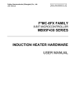
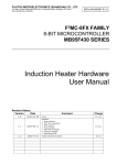
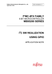
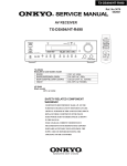
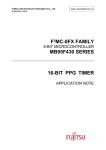
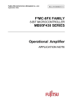
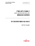
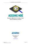
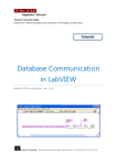
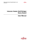
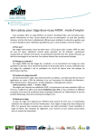
1
Fujitsu Semiconductor Design (Chengdu) Co., Ltd. User Manual MCU-AN-500087-E-12 F²MC-8FX FAMILY 8-BIT MICROCONTROLLER MB95F430 SERIES INDUCTION HEATER HARDWARE USER MANUAL Induction Heater C Library User Manual V1.2 Revision History Revision History Version Date 1.0. 2010-04-06 Updated by Modifications Folix First draft 1.1 Modified: 1.2 1. System Feature; 2. MCU Pin Assignment; 3. IGBT Feature; 4. Power Module; 5. IGBT Driver Module; 6. Pad Driver Module; 7. Main Board SCH; Update operation description 2010-08-11 Folix 2010-9-10 Terry This manual contains 22 pages. 1. The products described in this manual and the specifications thereof may be changed without prior notice. To obtain up-to-date information and/or specifications, contact your Fujitsu sales representative or Fujitsu authorized dealer. 2. Fujitsu will not be liable for infringement of copyright, industrial property right, or other rights of a third party caused by the use of information or drawings described in this manual. 3. The contents of this manual may not be transferred or copied without the express permission of Fujitsu. 4. The products contained in this document are not intended for use with equipment which require extremely high reliability such as aerospace equipment, undersea repeaters, nuclear control systems or medical equipment for life support. 5. Some of the products described in this manual may be strategic materials (or special technology) as defined by the Foreign Exchange and Foreign Trade Control Law. In such cases, the products or portions theory must not be exported without permission as defined under the law. © 2010 Fujitsu Semiconductor Design (Chengdu) Co., Ltd. MCU-AN-500087-E-12 – Page 2 Induction Heater C Library User Manual V1.2 Contents Contents REVISION HISTORY .............................................................................................................. 2 CONTENTS ............................................................................................................................ 3 1 INTRODUCTION ................................................................................................................ 4 2 SYSTEM FEATURES ........................................................................................................ 5 3 SYSTEM INTRODUCE ...................................................................................................... 6 3.1 Hardware Block Diagram .......................................................................................... 6 3.2 MCU Resource Usage .............................................................................................. 6 3.3 MCU Pin Assignment ................................................................................................ 7 3.4 IGBT Features .......................................................................................................... 8 4 SYSTEM HARDWARE ...................................................................................................... 9 4.1 System Connect Diagram ......................................................................................... 9 4.2 Front Board ............................................................................................................. 10 4.3 Main Board .............................................................................................................. 11 5 MODULE DESCRIPTION ................................................................................................ 12 5.1 Power Module ......................................................................................................... 12 5.2 IGBT Driver Module ................................................................................................ 13 5.3 Pad Driver Module .................................................................................................. 14 6 SYSTEM OPERATION .................................................................................................... 15 6.1 Key & Led Definition................................................................................................ 15 7 DEBUG AND PROGRAMMING ...................................................................................... 17 7.1 Debug Environment and Tools................................................................................ 17 7.2 Hardware Setup ...................................................................................................... 17 7.3 MCU Programming ................................................................................................. 17 8 ADDITIONAL INFORMATION ......................................................................................... 18 9 APPENDIX ....................................................................................................................... 19 9.1 Front Board SCH and BOM-List.............................................................................. 19 9.2 Main Board SCH and BOM-List .............................................................................. 20 9.3 List of Figures ......................................................................................................... 22 MCU-AN-500087-E-12 – Page 3 Induction Heater C Library User Manual V1.2 Chapter 1 Introduction 1 Introduction This document introduces how to use the electromagnetic oven hardware. The hardware includes two PCB boards (main board and front board), a fan and a pad. MCU-AN-500087-E-12 – Page 4 Induction Heater C Library User Manual V1.2 Chapter 2 System Features 2 System Features ¾ Power Control ¾ Fan Control ¾ Fan Delay Off ¾ Buzz Control ¾ Led Display ¾ Keyboard ¾ Kettle Detect ¾ Kettle Empty Detect ¾ Timing Power Off (3Hours) ¾ Constant Power Heating ¾ Constant Temperature Heating ¾ IGBT Temp Detect ¾ Plate Temp Detect ¾ IGBT Temp Higher Protect (120°C) ¾ Plate Temp Higher Protect (300°C) ¾ Kettle Empty Protect (300°C) ¾ Sensor Open/Short Detection ¾ Over Current Protect (18A) ¾ Over Voltage Protect (260V) ¾ Lower Voltage Protect (150V) ¾ Surge Protect (1000V) ¾ No Operation for 2 Hours, auto turn off, if no timer In the system design, we will use some feedback signals to protect system or calculate watt. The protect signal includes over current, over voltage, surge voltage and kettle detect. If anyone of them appears, the system must stop work. If the IGBT temperature is raised over 60°C, the fan must turn on. If the IGBT temperature is raised over 120°C, the system must stop work. If the kettle is empty, the plate temp will rise. If the temp is raised up to 300°C, the system must stop work. MCU-AN-500087-E-12 – Page 5 Induction Heater C Library User Manual V1.2 Chapter 3 System Introduce 3 System Introduce 3.1 Hardware Block Diagram Figure 3-1: Hardware Block Diagram The electromagnetic eddy current heating is our system theory. We use the PWM to control the IGBT to generate the heating eddy current. The fan is use to cool the IGBT. The feedback signal is used to protect the system and calculate power. 3.2 MCU Resource Usage MB95F434K Resource Usage No. Resource Usage Info Remark 1 VCC 5.0V 2 ROM 3 RAM 4 OSC Clock 16.25MHz 5 CPU Clock 8.125MHz 6 GPIO 6 Pins LED COM(5),Start 7 INTxx 1 Pins (Internal) Pad osc 8 8/16Bit PPG(Timer) 1 Pins(PPG) 9 ANxx 4 Pins 10 UART0 LED Display 11 Debug 1 Pins 12 Watchdog Timer Monitor System 13 16Bit Timer0 Keyboard Sample 14 16Bit Timer1 10MS Timer MCU-AN-500087-E-12 – Page 6 Protect,Error Induction Heater C Library User Manual V1.2 Chapter 3 System Introduce 3.3 MCU Pin Assignment No. Name Define Note Remark 1 PG2/PPG0/X1A/OUT1 sub oscillator sub oscillator 2 PG1/TRG0/ADTG/X0A/BZ/OUT0 sub oscillator sub oscillator 3 VCC VCC Vcc 4 C C C 5 P60/OPAMP_P OPAMP_P Current by Resistor 6 P61/OPAMP_N OPAMP_N 7 P62/OPAMP_O P62 LED COM2 8 P12/EC0/UI/DBG P12/DBG Debug 9 P00/INT00/AN00 P00 Start IGBT 10 P01/INT01/AN01/BZ BZ Buzzer 11 P02/INT02/AN02/UCK/TRG0 UCK Serial Clock 12 P03/INT03/AN03/UO/PPG0 UO Serial Data 13 P04/INT04/AN04/UI/HCLK1 AN04 AC voltage Measuring 14 P05/INT05/AN05/TO0/HCLK2 AN05 AC Current Measuring 15 P06/INT06/AN06/TO1 AN06 Temperature for IGBT 16 P07/INT07/AN07/EC0 AN07 Temperature for plate 17 P70/CMP0_O/OUT0/TRG0 P70 LED COM4 18 P71/CMP0_P CMP0_P PAD-L+ Input 19 P72/CMP0_N CMP0_N PAD-L- Input 20 P73/CMP1_O/OUT1/PPG0 PPG0 PPG-IGBT 21 P74/CMP1_P CMP1_P OverCurrent Input Reference 22 P75/CMP1_N CMP1_n OverCurrent Input Compare 23 P76/CMP2_O/UCK P76 LED COM3 24 P63/CMP2_P CMP2_P OverVoltage Input Reference 25 P64/CMP2_N CMP2_N OverVoltage Input Compare 26 P65/CMP3_O/UO P65 LED COM0 27 P66/CMP3_P CMP3_P Surge Reference Input 28 P67/CMP3_N CMP3_N Surge Compare Input 29 PF2/RSTX PF2 Reset 30 PF0/X0 X0 oscillator 31 PF1/X1 X1 oscillator 32 VSS VSS Vss MCU-AN-500087-E-12 – Page 7 Induction Heater C Library User Manual V1.2 Chapter 3 System Introduce 3.4 IGBT Features MCU-AN-500087-E-12 – Page 8 Induction Heater C Library User Manual V1.2 Chapter 4 System Hardware 4 System Hardware 4.1 System Connect Diagram The whole system includes pad, fan, main board and front board. They are connected as below. Figure 4-1: System Connection Diagram Connecting Order: Pad to main board Pad temp to main board Fan to main board Front board to main board MCU-AN-500087-E-12 – Page 9 Induction Heater C Library User Manual V1.2 Chapter 4 System Hardware 4.2 Front Board Figure 4-2 is the front board image. It is made up of eight LEDs, a 4-bit digital LED and eight buttons. 2 1 3 4 Figure 4-2: Front Board 1. Connector, connect to main board. 2. Eight LEDs, to display some statuses. 3. 4-bit digital LED, to display power and time. 4. Eight buttons, to control the system. MCU-AN-500087-E-12 – Page 10 Induction Heater C Library User Manual V1.2 Chapter 4 System Hardware 4.3 Main Board Figure 4-3 is the main board image. It is made up of power module, mcu control module and IGBT driver module. 1 2 Power 3 IGBT Driver 4 5 Mcu 7 6 8 9 Figure 4-3: Main Board 1. 220VAC, to supply power. 2. Pad Connector, to connect the pad. 3. Buzzer, to note some status. 4. Pad temp connector, to test the pad temperature. 5. IGBT power, to supply power to the IGBT. 6. IGBT, is the IGBT chip. 7. MCU, to control the system. 8. Fan connector, to control the fan. 9. Front connector, to connect the front board. 10. Debug connector, to connect the simulator. MCU-AN-500087-E-12 – Page 11 1 Induction Heater C Library User Manual V1.2 Chapter 5 Module Description 5 Module Description 5.1 Power Module The 220V is connected by “ICN1” and “ICN2”. The 220V is rectified by “U4”, and supplied to the pad. The “U11” is a 15V power module. It supplies power to the MCU and IGBT driver. MCU-AN-500087-E-12 – Page 12 Induction Heater C Library User Manual V1.2 Chapter 5 Module Description 5.2 IGBT Driver Module The “START” is the system enable signal. When it is high, the system is enabled, or else disabled. The “PPG-IGBT” is the IGBT drive signal. When it is high, the IGBT is opened, or else closed. The duty of the “PPG-IGBT” is to decide the pad heating power. MCU-AN-500087-E-12 – Page 13 Induction Heater C Library User Manual V1.2 Chapter 5 Module Description 5.3 Pad Driver Module When the IGBT (U9) is opened, the current flows over the “PAD”. The “PAD” is a coil, so it will save the power. The current direction is from left to right. Once the IGBT is closed, because the “PAD” is a coil, the current direction is still from left to right. Because there is a C11, so it and the “PAD” are made an oscillation loop, and the power will be saved in the C11. When the system is working, if there is a cooker on the “PAD” coil, the cooker will be heated. MCU-AN-500087-E-12 – Page 14 Induction Heater C Library User Manual V1.2 Chapter 6 System Operation 6 System Operation 6.1 Key & Led Definition The system key buttons and LEDs are defined as below. Error Clear Timer CaoCai HuoGuo DunCai Timer BaoTang View Inc Dec M-Inc ¾ Key Definitions Clear---------------Clear the timer. Timer---------------Set the timer. Inc-------------------Power increase. Dec-----------------Power decrease. M-Inc---------------Mode increase. M-Dec--------------Mode decrease. View----------------Change the display, power or timer. Power--------------Turn on or turn off the device. ¾ Led Definitions Error----------------Error display. Timer---------------Timer display. CaoCai-------------Mode display. HuoGuo-------------Mode display. DunCai-------------Mode display. BaoTang-------------Mode display. BaoWen-------------Mode display. Power----------------Power display. ¾ MCU-AN-500087-E-12 – Page 15 M-Dec BaoWen Power Power Induction Heater C Library User Manual V1.2 Chapter 6 System Operation ¾ Error Code Error Code Description 0xE0 Power under voltage 0xE1 Power over voltage 0xE2 Power over current 0xE3 Main sensor over 300℃ 0xE4 Main sensor break circuit 0xE5 Main sensor short circuit 0xE6 Main sensor temp not change 0xE7 IGBT temp over 120℃ 0xE8 IGBT sensor break circuit 0xE9 IGBT sensor short circuit 0xF0 Kettle is empty Notes 0xF1 6.2. Operation Description Turn On/Off When we have connect the power, the “Power” led will light. We can push the “Power” button to turn on the device, and the “Power” led will start wink. At anything, we can push the “Power” button to turn off the device. Mode Change When we turn on the device, the system is in standby. We must push the “M-Inc” or “M-Dec” to start the system. The system has six work modes. You can push the “M-Inc” and “M-Dec” to change the work mode. Power Change In normal, you can use the “Inc” or “Dec” button to change the power, and the range is from 200W to 2100W. When you change the power, the display will automatically change also. Timer Set At first, we push the “Timer”, the system will enter timer setting mode. We can push the “Inc” or “Dec” to change the timer time. When we push the “Timer” again, the timer will be set and started, and the “Timer” led will wink. If we want stop the timer, we must push the “Clear”. Display Change If you push the “View”, you will change the display information between power and time. MCU-AN-500087-E-12 – Page 16 Induction Heater C Library User Manual V1.2 Chapter 7 Debug and Programming 7 Debug and Programming 7.1 Debug Environment and Tools Name Description Manufacturer Notes Windows XP Pro PC OS Microsoft SP2 Softune V3 Software Developing IDE Fujitsu For FFMC-8L MB95F434K Emulator MCU Emulator Fujitsu --- 7.2 Hardware Setup The basic hardware connection is as below: 7.3 MCU Programming We can programme the MCU by the simulator. The basic hardware connection is shown in “7.2 Hardware Setup”. MCU-AN-500087-E-12 – Page 17 Induction Heater C Library User Manual V1.2 Chapter 8 Additional Information 8 Additional Information For more Information on FUJITSU semiconductor products, visit the following websites: English version address: http://www.fujitsu.com/cn/fsp/services/mcu/mb95/application_notes.html Chinese version address: http://www.fujitsu.com/cn/fss/services/mcu/mb95/application_notes.html MCU-AN-500087-E-12 – Page 18 Induction Heater C Library User Manual V1.2 Chapter 9 Appendix 9 Appendix 9.1 Front Board SCH and BOM-List ¾ Front Board SCH Front Board BOM-List MCU-AN-500087-E-12 – Page 19 Induction Heater C Library User Manual V1.2 Chapter 9 Appendix 9.2 Main Board SCH and BOM-List ¾ Main Board SCH ¾ Main Board BOM-List Main Part List Index Reference Value Footprint Quantity 1 B1 BM-330H BGM-330H 1 2 C1 C2 C3 C4 C5 C13 C21 C23 104Z C0805 8 3 C6 C12 C22 C24 100uF/25V CAP100V25 4 4 C7 C8 C9 C10 30P C0805 4 5 C11 0.33uF/1200V HVCAPD33 1 6 C14 5uF/275V HVCAP5U 1 7 C15 2uF/275V HVCAP2U 1 8 C16 681 C0805 1 9 C17 221 C0805 1 10 C18 103 C0805 1 11 C19 2.2uF/25V CAP2D2V25 1 12 C20 470uF/25V CAP470V25 1 13 CN1 CN2 CN3 CON2_1 CON2_1 3 14 CN4 JMP2_1 JMP2_1 1 15 CN5 JMP5_2 JMP5_2 1 MCU-AN-500087-E-12 – Page 20 Description Induction Heater C Library User Manual V1.2 Chapter 9 Appendix 16 CR1 470V RV 1 17 D1 Power LED 1 18 D2 D8 D9 D10 D11 D12 DI4148 DI4007 6 19 D3 D4 D5 DI4007 DI4007 3 20 D7 20V DI4007 1 21 F1 Fuse FUSE-90 1 22 ICN1 ICN2 ICN3 ICN4 PCN4 PCN4 4 23 J1 CON10_1 CON10_1 1 24 L1 4.7uH R_6_2_10 1 25 L2 400uH L-400-90 1 26 Q1 Q4 Q5 Q6 Q8 8050 SOT-23-8050 5 27 Q2 D667 TO-92-D667 1 28 Q3 S8550 TO-92-8550 1 29 Q7 S8050 TO-92-8050 1 30 R1 3.3R/1W R_11_4_16 1 31 R2 R3 330R R0805 2 32 R4 R5 R8 5.1k R0805 3 33 R6 R9 0R R0805 2 34 R7 330k/2W R_15_5_22 1 35 R10 R11 R15 470k/2W R_15_5_22 3 36 R12 R13 R25 R36 R37 10k R0805 5 37 R14 R17 10R/0.5W R_11_4_16 2 38 R16 R29 3.3k R0805 2 39 R18 R20 4.7k R0805 2 40 R19 6.8k R0805 1 41 R21 0.01 R_PWR 1 42 R22 9.1k R0805 1 43 R23 10k R_6_2_10 1 44 R24 300R R0805 1 45 R26 R27 R28 27k R0805 3 46 R30 1.2k R0805 1 47 R31 500R R_V 1 48 R32 51k R0805 1 49 R33 R34 R35 1k R0805 3 50 RT1 100k R_6_2_10 1 51 RT2 50k R_6_2_10 1 52 T1 1:1000 TRANSFER_CUR 1 53 U1 MB95HI434 LQFP-32 1 54 U2 Buzz BUZZER 1 55 U3 78L12 TO-220 1 56 U4 GBP04 Rectifier-90 1 MCU-AN-500087-E-12 – Page 21 Induction Heater C Library User Manual V1.2 Chapter 9 Appendix 57 U9 IGBT TO-247-90 1 58 U11 AC-DC PWR Module 1 59 U12 78L05 TO-220 1 60 X1 16.0MHz CRYSTAL 1 61 X2 32.768KHz CRYSTAL 1 9.3 List of Figures Figure 3-1: Hardware Block Diagram ....................................................................................... 6 Figure 4-1: System Connection Diagram ................................................................................. 9 Figure 4-2: Front Board .......................................................................................................... 10 Figure 4-3: Main Board .......................................................................................................... 11 MCU-AN-500087-E-12 – Page 22