1
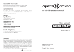
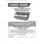
SYSTEMS, INC
Ozone System
Installation and Owner’s Manual
Corona Discharge
RK 8 GRAM
Ozone Generator
421A South Andreasen Drive
Escondido, CA 92029
(760) 746-7400
Copyright © 1995 • RK2 Systems, Inc. • Reproduction of any kind is prohibited • Rev. 1097
IMPORTANT SAFETY INSTRUCTIONS
1.
PLEASE FOLLOW ALL INSTALLATION INSTRUCTIONS.
2.
All electrical connections should be made by a licensed, qualified electrician.
3.
Before attempting any electrical connections, be sure all power is off at the main
circuit breaker.
4.
Install the ozone generator using nonmetallic plumbing.
5.
Install the provided ozone check valves to prevent water from contacting the
electrical equipment.
6.
The electrical supply for this product must include a suitably rated switch or circuit
breaker to open all ungrounded supply conductors to comply with Section 422-20
of the National Electrical Code, ANSI/NFPA 70-1987. This means of
disconnecting the equipment must be readily accessible to the operator.
7.
Be sure to bond (ground) the system using the copper bonding lug on the bottom
of the system. The system should be bonded with solid copper wire conforming
with all local, state and national electrical codes.
8.
Ambient temperature around the equipment should be between 40° and 100°F
(4.5° to 38°C). If the equipment is installed in an environment with temperatures
over 100°F, additional air cooling must be provided. Installation without additional
air cooling in an environment where temperatures exceed 100°F for any
continuous 24-hour period will void the warranty.
9.
The system should be sized appropriately for its intended use by a qualified
professional familiar with the application. This equipment must be validated by
the manufacturer for its intended use.
10. SAVE THESE INSTRUCTIONS.
2
CORONA DISCHARGE (CD) OZONE SYSTEMS
Ozone is manufactured in the CD ozone generator by drawing in air, which is composed of 20% oxygen (0^), and
exposing it to multiple high voltage electrical discharges. This causes a percentage of the oxygen molecules to
dissociate and reassemble as ozone (Og). The ozone is drawn into the water by an injector/mixer, killing any
bacteria, viruses or mold spores it contacts. Ozone is generated on-site, eliminating the need to store toxic and
corrosive chemicals. The corona discharge method is the most efficient way to produce large amounts of ozone.
3-02 ²
÷ 2-03
Chemical Formula (simplified)
for Corona Discharge Ozone
In contrast to ultraviolet ozone generators, corona discharge systems produce a much higher concentration of ozone
and in much larger quantities. In addition, the annual expense of replacing lamps and checking ballasts is
unnecessary with corona discharge systems. Corona discharge ozone generation is the most economical and
effective method to use on most water treatment applications.
RK2 Systems manufactures high output corona discharge systems capable of producing enough ozone to oxidize
iron, sulfide, manganese and act as an efficient sanitizer in a variety of applications. Ozone reacts to water-borne
contaminants significantly faster than other disinfectants and the primary by-product is pure oxygen.
RK2 Systems ozone systems are built with the finest components available. All are air cooled and are most efficient
when used with a venturi injection system to create the best possible contact and mixing of ozone while
maintaining a high level of safety.
UNCRATING and INSPECTION
Shipping Terms
Unless special arrangements have been made, the ozone equipment wilt be shipped FOB RK2 Systems in
Escondido, CA. The freight charges will be prepaid and billed or shipped freight collect. Transfer of liability to the
freight company and the customer occurs as the equipment leaves the factory loading dock and is accepted by the
freight line.
Freight Inspection
All equipment should be thoroughly inspected immediately upon delivery. If any damage is noticed, promptly
notify the freight line and request an on-site inspection.
Unpacking
Typically, the equipment will arrive on a pallet. Compare me components with the packing list. Thoroughly inspect
all packing materials prior to discarding. Inspect all plumbing fittings and tubing for packing material inadvertently
lodged in any openings.
PRODUCT DESCRIPTION
The RK2 Systems corona discharge ozone system consists of three main components:
• Ozone Generator
• Air Preparation Unit
• Venturi Injector Manifold
The optional equipment which can be used with the ozone generator on larger installations includes:
• Contact Vessel
• Booster Pump
• Electrical Interlock Box
• ORP Controller
• Dissolved Ozone Monitor
Ozone Generator
The ozone generator houses the ozone reaction chamber(s), power supply and all electrical components directly
related to the production of ozone. Ozone is produced when the feed gas is exposed to a high voltage electrical
current inside the reaction chamber.
Air Preparation
The RK2 Systems ozone system may be equipped with a heat regenerative desiccant air dryer. Corona discharge
ozone generators are much more effective, produce more ozone and require far less maintenance if an air preparation
unit is included. The air preparation system lowers the dew point of the feed gas. Moist feed gas (air) will cause
nitric acid to form inside the generator which decreases ozone production and if not removed, causes corrosion and
eventual failure of the generator's internal components. The ability of the ozone generator to produce ozone is
drastically reduced as the dew point rises above -80/C. The air dryer desiccant material has an average life
expectancy of five years under normal use.
3
Injector Manifold
The ozone gas is drawn into the water line by means of a venturi injector manifold. This allows the ozone to be injected
into the water under a vacuum condition, which is the safest, most efficient technology available. The venturi
utilized in
the injector manifold operates via a pressure differential (much like a carburetor). The amount of ozone drawn into it
depends on the water flow and pressure on the inlet and outlet sides. A pressure differential of at least 25 psi must be
maintained between the well (or booster pump) and system back pressure for the venturi to operate correctly. Proper
function of the venturi/ozone system will occur only if the pressure differential is maintained. For highest
efficiency, at
least 10" of vacuum at the venturi suction port and 25 psi at the venturi outlet must be maintained. RK2 Systems
stocks a complete line of high-efficiency venturi injectors from 4-100 GPM.
INJECTOR MANIFOLD (1// Inlet and Outlet)
Ball Valve
Contact Vessel (optional)
To maximize the effectiveness of ozone, it must be thoroughly mixed and have adequate time to react with the
contaminants in the water before being filtered or utilized. Contact vessels are designed to achieve this necessary
mixing and contact time. RK2 Systems supplies several different types of contact vessels for a variety of
applications.
Booster Pump (optional)
If excessive back pressure is created in the water line by filters, pressure tanks or other system parameters, a
booster pump may be necessary to create a sufficient pressure differential across the venturi. This booster pump is
used in conjunction with a side stream ozone injection loop.
Electrical Interlock Box (optional)
The electrical interlock box is a multifunction electrical enclosure. It houses the Motor Control Interlock (MCI),
ORP Interlock and the Vacuum Interlock. The enclosure also acts as the air preparation monitoring station,
controlling the amount of intake air and monitoring the vacuum. The electrical interlock box gives the RK8g all the
safety interlocks and controls of our larger cabinet systems.
5
INSTALLATION
Placement of Equipment
Select a location for the ozone equipment that is as close as possible to the ozone injection point. Arrange the
components (ozone generator, air dryer and electrical interlock box, if so equipped) in a manner suitable for
convenient electrical access. The system component enclosures are not rain proof, so it is important to choose a
location that will keep the system away from direct weather and excessive heat.
Mounting holes are located on the back of all components for convenient wall mounting. Mounting hardware is
not provided.
Materials
Use Schedule 80 PVC for all plumbing connections whenever possible. Also, it is recommended that unions and
valves are used wherever practical. Ozone rapidly deteriorates a variety of compounds; the following is a list of
materials that may be used ...
... with ozone in gaseous phase (at high concentrations):
Viton
Teflon®
Stainless Steel
EPDM
Silicon
Kynar®
Hepalon
... with ozone in aqueous phase (at low concentrations):
Viton
Teflon®
Stainless Steel
EPDM
Silicon
Kynar®
Concrete
Hepalon
Schedule 40 PVC
Schedule 80 PVC
NOTE: Be sure to use good plumbing practices and install unions and isolation valves wherever the
situation dictates, i.e. pump or injector removal, etc. Secure all plumbing with unistrut or similar hardware.
Tubing Installation
1. Install braided tubing from the indicating desiccant chamber on the air dryer or oxygen generator to the brass
AIR INLET fitting on the bottom of the ozone generator (or the bottom of the electrical interlock box if so
equipped). If you are not using an electrical interlock box, skip Step 2 and go to Step 3.
2. If equipped with the electrical interlock box, continue running the braided tubing from the electrical interlock
box brass AIR OUTLET fitting to the brass barb AIR INLET fitting on the bottom of the ozone generator.
3. Install the ozone check valve assembly onto the injector. Connect the 1/4" Teflon* tubing from the Teflon*
OZONE OUT compression fitting on the bottom of the ozone generator to the Teflon® compression fitting
on the check valve assembly on the injector. Secure by tightening the fitting around the 1/4" Teflon® tubing after
insertion. (If equipped with the electrical interlock box, install the 1 /4" Teflon* tubing from the OZONE OUT
fitting on the bottom of the ozone generator to the stainless steel solenoid valve located on the top of the
electrical interlock box. Continue running the Teflon® line from the solenoid valve to the check valve
assembly on the injector.)
Check Valve Selection
The ozone check valve is an important component in preventing damage to the ozone generator. All RK2
Systems RK8g ozone generators are equipped with a PVC Body Viton Seal low pressure check valve on the
ozone outlet. A second check valve should be installed on the venturi injector ozone inlet. This check valve
should be matched to the application. A low pressure PVC Body Viton Seal check valve is appropriate for
applications where the system pressure will not exceed 40 psi. Higher line or system pressure installations require
a stainless steel check valve.
Note: The cracking pressure (the pressure at which the valve opens) of any check valves not sourced through
RK2 Systems must not exceed 0.5 Ib. (0.33 Ib. is recommended.)
6
INITIAL VENTURI INJECTOR MANIFOLD CALIBRATION
RK2 Systems air preparation and ozone generation systems Model RK8g is a vacuum type and will require
adjustment of the air flow through the system. An SCFH (Standard Cubic Feet per Hour) gauge is used to
accurately measure the amount of air flowing through the ozone delivery line on single speed injectors (in other
words, the amount of ozone being drawn into the water). Follow the directions and illustration below to
optimize flow through the injector:
Install the tube fitting into the upper hole on the back side of the SCFH gauge.
1.
2.
3.
4.
With the pump running, disconnect the tubing from the ozone outlet of the ozone generator and connect
the tubing to the fitting on the gauge.
While holding the gauge vertically, read the amount indicated on the gauge. Note: Do not obstruct the bottom
air hole on the gauge. The optimum flow is 14 SCFH for the RK8g on dried air and 14 SCFH on oxygen,
If the flow exceeds 20 SCFH, install an ozone resistant metering valve to restrict the flow to the correct
amount.
The injector has a ball valve to adjust the amount of flow. To adjust the SCFH, simply install the gauge
as above and open the ball valve completely. With the pump running, begin closing the ball valve until
the optimum
flow is achieved on the SCFH gauge. If possible, remove the ball valve handle to prevent tampering with the
setting.
.
7
FUNCTION CHART: CD-1500, CD15/AD & CD-2000
FEATURE
CONTROL
MODE
EXTERNAL
LOOP
POT
*
4-20 mA
OZONE
BYPASS
“BYPASS”
(Center Position)
N/A
N/A
N/A
IF REMOVED
(circuit open)
N/A
N/A
IF IN PLACE
(circuit closed)
YES
N/A
IF REMOVED
(circuit open)
N/A
4 mA
IF IN PLACE
(circuit closed)
N/A
4 mA
0%
IF REMOVED
(circuit open)
N/A
20 mA
0%
IF IN PLACE
(circuit closed)
N/A
20 mA
100%
MANUAL
CONTROL
4-20mA
“VARIABLE”
(Left Position)
“4-20mA”
(Right Position)
OZONE
OUTPUT
0%
0%
0-100%
0%
OZONE BYPASS feature provides zero (0%) ozone output, with other controls (EXTERNAL
LOOP, POT* or 4-20 mA) having no effect on ozone output. This function is for set up (SCFH, etc.)
or testing/troubleshooting (electrical, etc.) of the equipment only.
MANUAL CONTROL feature allows for manual control of the ozone output (0-100%) using the pot'
with the external loop circuit closed. When the external loop circuit is open, the ozone output will
be zero (0%) and cannot be manually controlled. Switching between manual control (0-100% output)
and no control (0% output) is achieved by installing or removing the external loop.
4-20 mA CONTROL feature allows for control of the ozone output (0-100%) from an external source
(ORP. etc.). The external source provides a 4 mA signal to give zero (0%) ozone output, and a 20 mA
signal to give full (100%) ozone output with the external loop circuit closed. Any % between 0%
and100% is achieved by varying the 4-20mA signal with the external loop circuit closed. Opening the
external loop circuit will reduce the ozone output to zero (0%) regardless of the 4-20mA signal level.
* POT is an abreviation for potentiometer. The POT is the adjustment knob labeled MIN-MAX on
the bottom of the ozone generator. This knob is used to manually control the ozone output in the
MANUAL- VARIABLE position.
8
SYSTEMS, INC
RK 8 GRAM
Maintenance & Troubleshooting Manual
Parts & Warranty
9
MAINTENANCE
Ozone Generator
A word of caution: There is extremely high voltage inside the ozone generator. If you suspect a problem,
disconnect the power to the unit at the service disconnect box or main electrical panel and immediately contact
your RK2 Systems distributor. Inspect the ozone delivery line check valves daily for water seepage and replace
the injector check valve yearly.
Monthly Service
1. Clear the ozone generator cabinet air filter:
This filter must be cleaned regularly. Depending on the location of the unit, it may be necessary to clean the
air filter monthly. The filter element is located on the bottom of the cabinet (see illustration below). This is
the air intake element for the cooling fan and may therefore require the most frequent cleaning. The
element may be cleaned with soap and water and should be dried completely before reinstalling.
Note: In a clean environment, this procedure may only need to be performed every three months.
IMPORTANT: CLEAN THIS FILTER REGULARLY! FAILURE TO DO SO WILL PROMOTE
OVERHEATING AND WILL VOID THE WARRANTY!
CW
2. Check valves:
Two Kynar® check valves are built into the ozone delivery system where the ozone tubing attaches to the ozone
generator. There is also an anti-syphon loop at the proton frac venturi connection. The purpose of these is to
prevent water from backing up into the ozone generator. The Teflon® ozone delivery line(s) should be
inspected daily to insure water is not flowing back into the ozone generator. Check valve should be replaced
yearly. Note: The only time it should be possible for water to flow back toward the ozone generator is during
a system shutdown. Always inspect for water seepage during this time.
Yearly Service
1. Replace the cooling fan filters. Failure to do so will promote over heating.
2. Replace the air inlet particulate filter on the ozone generator. This Filter precevents small particles from
entering the reaction chanmber. It must be replaced annually to prevent clogging.
3. Replace all check valves. There is no such thing as a 100% check valve. Yearly replacement can prevent many
of the back flow problems. All stainless steel check valves should be rebuilt. Along with the yearly check valve
replacement, RK2 Systems recomments that a vacuum break be installed with all units operating on dried air
feed. Please contact your RK2 Systems distributor for more information about our vacuum break
10
4. Dielectric tubes are located in the reaction chambers of the ozone generator. These tubes should be
inspected periodically and cleaned if necessary. Once each year, remove one reaction chamber and inspect
the dielectric tube for debris. If the tube is clean and free of any debris, oil or dirt, it may be replaced and no
further maintenance is required. If the tube is dirty or cracked, all dielectric tubes must be inspected and
cleaned. Cracked dielectrics should be replaced. Please consult your RK2 Systems distributor, as the
improper installation of the dielectric may cause safety problems!
When the air that is introduced into the reaction chambers is high quality, the dielectric tubes should remain
clean for at least one year before inspection is required.
Removal of the Dielectric Tubes
a. Disconnect all the power to the system, including panel breakers, service disconnect box and main
circulation pump interlock.
b. Unplug the electrical terminal on the back of the drive module, disconnect the polypropylene
barbed air fitting and the Kynar® oz one fi ttin g.
c.
Remove the ozone reaction chamber(s) from the back plate.
d. Disconnect the high voltage wire from the coil. Remove the stainless steel nut and Kynar® center
rod from the center of the reaction chamber.
e. The Teflon® end caps can now be gently removed by slowly pulling straight out. The glass
dielectric will remain attached to one of the end caps.
f.
If the dielectric tube is dirty, clean the glass with Isopropyi alcohol. Do not use a solvent that will
leave an oily residue.
g.
Clean the inside of the stainless steel reaction chamber with a wire brush as necessary, then wipe
with Isopropyl alcohol.
h. Be sure all solvents have evaporated prior to reassembly.
Re-Installation of the Dielectric Tubes
a. Inspect the 0-rings and replace as necessary.
b. Tighten the end caps so that they are approximately 1/8" from the aluminum extrusion.
c. Replace the reaction chambers and connect the air and ozone lines.
d. Connect the high voltage wire to the coil.
e.
Readjust the system as necessary (see operating instructions).
5. Replace the desiccants.
On all AD-40 air dryers and ozone generators with built in air dryers, replace both the heating desiccant and
external indicating desiccant yearly. RK2 Systems air dryers are designed to be on 24 hours a day. Failure
to do so will allow moist air to be introduced into the reaction chamber. Improperly dried feed air will cause
nitric acid formation and premature dielectric failure.
Every Three Years:
1. Replace all cooling fans in the ozone generator.
Failure to do so will promote overheating.
2. Hone and rebuild reaction chambers.
In addition to cleaning the dielectric, the reaction chamber should be honed. A honing toot is available
through RK2 Systems distributors. The dielectric and reaction chamber should be cleaned as instructed in
the owners manual. The reaction chamber should be rebuilt using new o-rings to ensure a proper seal. Care
should be taken to ensure that the dielectric does not get damaged during this process.
Every Five Years:
1. Replace the dielectric.
The glass dielectric should be replaced. Any scratches, imperfections in the conformal coating, or chipping
in the
glass itself can cause serious damage to the ozone generator.
11
OZONE GENERATOR TROUBLESHOOTING
PROBLEM/SYMPTOM
POSSIBLE CAUSE
SOLUTION
Unit has a turn-on time delay
No power to unit
Blown fuse
Incorrect wiring connections
Bad power supply
Wait — the unit may take up to
8 seconds to turn on
Check switch
Replace fuse on bottom panel
Check wiring (see manual)
Contact distributor
Unit does not stay on
Defective check valve
Major unit failure
Inspect and replace if necessary
Contact distributor
Ozone cycles on and off
Overheating
Defective power
Clean fan filter, check fan
Check for constant power if not
timer controlled
Unit trips circuit breaker
Incorrect wiring
Incorrect circuit breaker
Check wiring (see manual)
Check and, if necessary, replace with
correct circuit breaker
‘OZONE’ indicator LED is not lit
Ozone card has become unseated from
its connector on the main circuit board
Plug the ozone card back into the
main circuit board
‘DRYER TIMER’ LED is
not flashing
Dryer timer card has become unseated
from its connector on the main
circuit board
Plug the dryer timer card back into
the main circuit board
‘HIGH TEMP’ indicator LED
is lit (unit is overheating)
Clogged fan filter
Clean or replace fan filter
Fan is not plugged in
Fan is not operating
Bad temperature sensor
Bad ozone card
Plug fan in
Contact distributor
Contact distributor
Contact distributor
Bad external wiring
Check wiring
External plug has become unseated
from its connector on the main
circuit board
Bad variable output control card
Bad main circuit board
Plug the external loop card back into
the main circuit board
Contact distributor
Contact distributor
Incorrect wiring
Check wiring (see manual)
Unit not grounded
Ground unit in accordance with
local codes
Return unit for major service or
completely disassemble and clean
Unit does not turn on, green
LED does not light
External control loop is not
functioning
You receive an electrical shock
upon touching the unit
Unit has been flooded
15
OZONE GENERATOR TROUBLESHOOTING
Continued
PROBLEM/SYMPTOM
POSSIBLE CAUSE
SOLUTION
Water in unit or
ozone delivery tubing
Defective check valve(s)
Replace check valve(s)
Excessive back pressure on
check valve
Back pressure not to exceed 40 psi —
if over 40 psi consult with
RK2 Systems distributor
Loose internal fittings
Defective O-ring seals in
reaction chamber
Loose fittings in the external
control loop
Defective reaction chamber
Inspect and tighten fittings
Check and replace if necessary
HV transformer is not plugged in
Plug the variable output control card
back into the main circuit board
Replace output control card
Inspect and replace if necessary
Ozone smell present
You suspect that no ozone
is being produced
Defective output control card
Dielectric failure
Variable output control
not working
Inspect and tighten fittings
Check and replace if necessary
Variable output control card has
become unseated from its connector
on the main circuit board
Defective output control card
Defective adjustment control
Plug the variable output control card
back into the main circuit board
Unit seems noisy
Not properly secured to wall/floor
Shipping damage
Fan blocked
Bolt it firmly into place
Locate and repair
Check and clear obstructions
Air dryer cold when operating,
dryer LED’s not lighting
Heater cartridge not plugged into
the main circuit board
Defective heater cartridge
Check all heater connections, plug
the heater cartridge back into the
drive card on the main circuit board
Replace heater cartridge
Air leak
Tighten fittings
Desiccant saturated in storage
Reactivate desiccant (as described
in manual)
Bad dryer card
Replace dryer card
Desiccant indicator cartridge
not blue in color
Air dryer not cycling
16
Replace the output control card
Contact the distributor
RK2 Systems, Inc. Limited One-Year Warranty
Summary of the Warranty
RK2 Systems, Inc. (“RK2”) makes every effort to assure that its products meet high quality and durability standards and warrants the
products it manufactures against defects in materials and workmanship for a period of one (1) year, commencing on the date of
original shipment from RK2, with the following exceptions: 1) The warranty period shall begin on the installation date if the installation
is performed within 90 days of the original shipment from RK2; 2) The warranty period shall begin on the date of the bill of sale to the
end user if the installation date is more than 90 days after the original shipment date. To validate the warranty, a warranty card,
accompanied by a copy of the bill of sale, must be returned to RK2 and must include the following information:
•
•
•
•
•
End user name
Complete address, including telephone number
Date installed
Complete model and serial number information
Name of company from which the unit was purchased
Repairs and replacement parts provided under this warranty shall carry only the unexpired portion of this warranty of 90 days,
whichever is longer.
Items Excluded from the Warranty
This warranty does not extend to any product and/or part from which the factory assigned serial number has been removed or which
has been damaged or rendered defective as a result of:
•
•
•
•
•
•
an accident, misuse, alteration or abuse
an act of God such as flood, earthquake, hurricane, lightning or other disaster resulting only from the forces of nature
normal wear and tear
operation outside the usage parameters stated in the product user’s manual
use of parts not sold by RK2
service or unit modification not authorized by RK2
Obtaining Service Under the Warranty
Any product and/or part not performing satisfactorily may be returned to RK2 for evaluation. a Return Goods Authorization (RGA)
number must first be obtained by either calling or writing your local authorized dealer, distributor or RK2 direct, prior to shipping the
product. The problem experienced with the product and/or part must be clearly described. The RGA number must appear
prominently on the exterior of the shipped box(es). The product and/or part must be packaged either in its original packing material or
in comparable and suitable packing material, if the original is not available. You are responsible for paying shipping charges to RK2
and for any damages to the product and/or part that may occur during shipment. It is recommended that you insure the shipment for
the amount you originally paid for the product and/or part.
If, after the product and/or part is returned prepaid and evaluated by RK2, it proves to be defective while under warranty, RK2 will, at
its election, either repair or replace the defective product and/or part and will return ship at lowest cost transportation prepaid to you
except for shipments going outside the 50 states of the United States of America. If upon inspection, it is determined that there is no
defect or that the damage to the product and/or part resulted from causes not within the scope of this limited warranty, then you must
bear the cost of repair or replacement of damaged product and/or part and all return freight charges. Any unauthorized attempt by the
end user to repair RK2 manufactured products without prior permission shall void any and all warranties. For service, contact your
authorized dealer or distributor or RK2 direct at (760) 746-7400.
Exclusive Warranty
There is not other expressed warranty on RK2 products and/or parts. Neither this warranty, or any other warranty, expressed or
implied, including any implied warranties or merchantability of fitness, shall extend beyond the warranty period. Some states do not
allow limitations on how long an implied warranty lasts, so that the above limitation or exclusion may not apply to you.
Disclaimer of Incidental and Consequential Damages
No responsibility is assumed for any incidental or consequential damages; this includes any damage to another product or products
resulting from such a defect. Some states do not allow the exclusion or limitation of incidental or consequential damages, so that
above limitation or exclusion may not apply to you.
Legal Remedies of Purchaser
This warranty gives you specific legal rights and you may also have other rights which vary from state to state.
THIS STATEMENT OF WARRANTY SUPERSEDES ALL OTHERS PROVIDED TO YOU AT ANY PRIOR TIME.
RK2 Systems, Inc. • 421 A South. Andreasen Drive, Escondido, CA 92029 • (760) 746-7400 • Fax (760) 746-7460