1
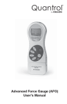
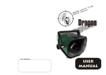
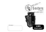
RVC900N Rotary Valve Controller
Rev. A - Nov. 10
RVC900N Series
ROTARY VALVE CONTROLLER
User Manual
RVC900N Rotary Valve Controller
This page intentionally left blank
Rev. A - Nov. 10
RVC900N Rotary Valve Controller
Rev. A - Nov. 10
1. TABLE OF CONTENTS
1. Table of contents
1
2. Designated use
2
3. For your safety
2
4. Technisa data
3
4.1 Parts & description
4
5. Included parts
5
6. Start operation
5
7. Operation
6
7.1 Display
7.2 Status LED´s
7.3 Operation keys
6
6
7
8. Parameter
8
9. Service Menu
9
9.1 Display
9.2 Settings
9
9
10. Electrical connections
10
10.1 Rotary valve
10.2 Foot switch
10.3 I/O-port
10
10
10
10.4 Wiring diagrams
11
11. Maintenance and cleaning
12
12. Disposal
12
1
RVC900N Rotary Valve Controller
Rev. A - Nov. 10
2. DESIGNATED USE
The digital rotary valve controller RVC900N is used for precise controlling of rotary
valves which work with a DC voltage of 0 – 24V, for example the PDV-1000 valve. The
RVC900N controls the air pressure on the material, and also the voltage to the rotary
valve for setting the speed of the valve.
With the integrated precision air pressure regulator, the air pressure on the material can
be set precisely. There are two different air pressure outputs for the RVC900N. One
output is continuous air pressure, the second output is a pulsed air pressure, as long, as
the rotary valve dispenses. An integrated digital pressure sensor at the inlet air gives an
additional point for the process safety.
3. FOR YOUR SAFETY:
WARNING:
If the RVC900N is used for other functions as described below, it could come to
personal or material damage. Use the RVC900N controller only for the functions, which
are explained in this user manual. Fisnar Inc. is not responsible for personal or material
damages, which happen because of incorrect usage.
DO NOT modify the RVC900N.
DO NOT attempt to repair or use spare parts without first contacting Fisnar.
DO NOT use anything but recommended Fisnar accessories..
SAFETY PRECAUTIONS:
The RVC900N works with 100 – 240V AC voltage. By touching the 100 – 240V AC
voltage, there exists danger of life!! Because of this, the RVC900N must be
disconnected from the AC input cable, before opening the housing. It is only allowed for
authorized electrical experts to open the housing.
DO NOT exceed the maximum allowed power / settings.
Always wear protective gear.
Before using the RVC900N please review the safety datasheets of the dispensing
material
No smoking or fire by flammable materials.
The RVC900N is only allowed for use indoors.
Due to the electronic nature of this equipment and the potential for a spark or
generation of heat, note that this equipment most NOT be used with any explosive
material or in an explosive type environment.
2
RVC900N Rotary Valve Controller
Rev. A - Nov. 10
4. TECHNICAL DATA
Measurements
: 9 ¼” x 8 ¼” x 2 ¾” (235 x 210 x 70mm)
Weight
: 3.6lbs. (1.65kg)
Power Supply
: 100 – 240V AC 50/60Hz
Internal Voltage
: 24V DC
Voltage Rotary Valve
: 0 ... 24V DC (PWM)
Dispense Time
: 0.01 - 999 sec.
Air Inlet
: 0-100psi (0-7bar) Display: digital
Air Outlet
: 0-58 psi (0-4bar) precise pressure regulator
- continuous
- pulsed
Parameter Display
: 128 x 64 Pixel graphical display
Programs
: 8 programs
3
RVC900N Rotary Valve Controller
Rev. A - Nov. 10
4.1 PARTS & DESCRIPTION
[Front Side]
Air pressure regulator
Operating keys
Pressure
gauge for
air outlets
Graphic display
Status LED´s
[Back Side]
Rotary valve
0-24V DC (PWM)
Air inlet
0–7 bar (0-100psi)
Footswitch
I/O-Port
Power
switch
Fuse 2A T
4
Air outlet
continuous
Air outlet
pulsed
Power inlet
RVC900N Rotary Valve Controller
Rev. A - Nov. 10
5. INCLUDED PARTS:
RVC900N Controller
Power Inlet cable
Tube for Air Inlet
User Manual
Foot Pedal
6. START OPERATION:
Connect the power inlet cable to the power inlet connector on the backside.
Connect the air inlet tube from the compressor to the air inlet on the backside of the
RVC900N.
Connect the foot pedal or dispense cable to the footswitch connector on the backside of the
RVC900N. Also connect the rotary valve cable to the connector in the rear of the RVC900N
controller.
Depending on your application, use the continuous or pulsed air outlet for the air supply of
the material reservoir. Adjust the air outlet pressure with the pressure regulator on the front
side of the RVC900N. A typical air pressure is less then 30psi (2 bar) for standard
applications with a rotary valve. If material comes out of the tip, without dispensing with the
rotary valve, reduce the air pressure on the material reservoir.
Switch the RVC900N on. The display shows the initialization and the installed software
version. After 5 sec, the display switches automatically to the standard screen and is ready
for operation.
Check the pressure input (e.g. P-IN: 80psi (5.6bar)) in the display to be sure, that the air
input pressure is connected.
5
RVC900N Rotary Valve Controller
Rev. A - Nov. 10
7. OPERATION:
7.1 Display: (values can be different)
Marking
Parameters
Dispense
Speed
Wait time
Retract
Mode
CW
Program
/ Mode
Rotating
Direction
CW / CCW
*
:
:
:
:
:
Selected values
002.55 s
070
0.20 s
0.50 s
Prog: 1
P-IN 80psi
C: 000027
Cyclecounter
volatile
Display:
Selected
air inlet pressure Program
7.2 Status LED´s
Below the display are the status-LED´s of the RVC900N.
RUN:
The RUN LED will turn on when the motor of the rotary valve is running.
Independent to the rotation direction.
ALARM:
The ALARM LED lights, during the following conditions:
Pressure alarm is active
Motor current overload (only active for speed >50)
External alarm signal on the I/O-Port
6
RVC900N Rotary Valve Controller
Rev. A - Nov. 10
7.3 Operating keys:
PROG - switches to the next program
SAVE - saves the actual parameters.
Press the SAVE key for 2 sec. and select the wanted program with the UP
/ DOWN keys and press SAVE again to store the parameters. If no
different program is selected, the parameters get automatically saved in
the actual program.
PURGE - starts the dispensing procedure.
UP - increases the selected value.
DOWN - decreases the selected value
SELECT - Moves the marking to the next display line.
7
RVC900N Rotary Valve Controller
Rev. A - Nov. 10
8. PARAMETER:
Select mode
Pressing the PROG key switches to the next program and to manual mode
Manual:
In this mode, the dispense time does not get saved and the rotary valve
dispenses as long as the dispense signal is activated by one of the following:
footswitch / purge key / I/O-start.
After dispensing, the dispense time starts again at 0.00 sec.
PROG 1-7:
If one of the programs 1 – 7 is selected, the RVC900N dispenses as long as
the value of the dispense time is set for. This dispense cycle is activated by
one of the following: footswitch / purge key / I/O-start.
This mode should be selected, if the rotary valve should always dispense for
the same time.
Set the dispense time:
The dispense time can be selected with the UP / DOWN keys, and set from 0.01 - 999.99
sec.
Set the rotation speed:
The rotation speed of the rotary valve can be selected in linear steps.
The value from 001 - 100 is related to the rotary valve voltage 0 - 24V.
Set the wait time:
The wait time is the pause time between end of dispensing and starting the retract of the
rotary valve. This value is limited to max. 5 sec.
Set the retract:
The retract is the time, which the rotary valve moves in the inverted direction to the
dispense direction. With this function, dropping of material out of the dispense tip, after
finishing the dispense procedure can be prohibited. This value is limited to max. 5 sec.
Cycle counter:
The cycle counter counts the dispensing procedures after switching ON the RVC900N
controller. The memory of the cycle counter is volatile and gets reset to 000000 after
switching OFF the unit.
Rotation Direction:
The rotation direction of the rotary valve can be set for clockwise and counter clockwise.
The selected direction is shown in the display as follows:
CW:
CCW:
Clockwise - spindle moves clockwise
Counter clockwise - spindle moves counter clockwise
The rotation direction can be selected in the SERVICE MENU
8
RVC900N Rotary Valve Controller
Rev. A - Nov. 10
Keylock:
By pressing SAVE + PRG at the same time, a key lock for the RVC900N can be activated.
An activated key lock is shown in the display (lower right hand corner) with the symbol:
By pressing SAVE + PRG again, the keylock is deactivated.
9. SERVICE MENU: (press the UP + DOWN keys during initialisation)
9.1 Display:
SERVICE
Language
Direction
P-Unit
P-Alarm
Service
CW
:*
:
:
:
:
Selected language
E
CW
PSI
80 PSI
000000239
Selected rotation direction
Selected pressure unit
Selected pressure limit
Service counter
C: 000027
9.2 Settings:
Language:
Pressing UP / DOWN keys switches between English and German language.
Direction:
Pressing UP / DOWN keys switches between CW / CCW rotating direction for the rotary
valve:
CW:
Clockwise - spindle moves clockwise
CCW:
Counter clockwise - spindle moves counter clockwise
P-Unit:
Pressing UP / DOWN keys switches between PSI and BAR as unit for the digital displayed
pressure.
P-Alarm:
By pressing the UP / DOWN keys, the value for the low pressure alarm-limit can be
selected. If the input pressure is lower than the selected limit, the RVC900N controller
switches to ALARM mode and no new dispensing is possible.
Service:
Service counter – not resettable
NOTE: Press the save key to store new settings. The unit will reboot itself.
If you do not want to store new settings, turn off the power and turn on again.
9
RVC900N Rotary Valve Controller
Rev. A - Nov. 10
10. ELECTRICAL CONNECTIONS
10.1 Rotary Valve:
type:
pins:
pin 1 (red)
Pin 2
mating connector:
LEMO connector female 2-pol: EGG.00.302.CLL
0-24V rotary valve
0V (GND) rotary valve
LEMO connector male 2-pol. FGG.00.302.CLAD35
10.2 Footswitch:
pins:
connection between Pin 1 + 3 starts dispensing
10.3 I/O-Port:
type:
pins:
pin no.
1
2
3
4
5
6
7
8
9
10
11
12
13
14
15
15-pol. SubD female 2-doublerow
see following chart
Input / Output
---Output
-Input
Input
Input
--Output
Output
Input
Input
Input
Description:
Reserved
GND
24V DC
BUSY
GND
START
PRG1
PRG3
Reserved
Reserved
READY
ERROR
REMOTE
ERROR-IN
PRG2
10
Comment:
Reserved
GND
24V DC
Dispensing procedure active
GND
Starts dispensing
Program select Bit #1
Program select Bit #3
Reserved
Reserved
Ready signal
Error signal
Remote active
External Error input
Program select Bit#2
RVC900N Rotary Valve Controller
Rev. A - Nov. 10
10.4 Wiring Diagrams:
Digital Inputs:
A digital input is active, if the opto coupler is ON. If the opto coupler is connected to GND, the
input is activated:
Digital Outputs:
If the digital output is active, the opto coupler is electro conductive.
11
RVC900N Rotary Valve Controller
Rev. A - Nov. 10
11. Maintenance and cleaning
The RVC900N is maintenance free
Repairs should only be done by the manufacturer.
Clean the RVC900N controller only with a clean, smooth and dry cloth.
Do not use dissolvent material to clean the RVC900N controller. The foil at the front / back
plate or the housing paint can be destroyed.
12. Disposal
Dispose the product after the economic life-time according to the legal
requirements.
12