1
www.ubicom.com
Ubicom
SX Cross Assembler
User’s Manual
™
Lit. No.: UM02-04
SASM Cross Assembler User’s Manual Rev. 1.3
© 2000 Ubicom, Inc. All rights reserved.
Revision History
www.ubicom.com
Revision History
REVISION
RELEASE DATE
SUMMARY OF CHANGES
1.0
July 14, 1999
Initial Release
1.1
May 15, 2000
1.2
August 30, 2000
Updated to support SASM vl. 45.5 and higher
revisions
1.3
December, 2000
Updated to describe the improved macro language provided by SASM v1.46, including
minor revisions 1.47 and 1.48.
Updated to reflect latest SX devices
©2000 Ubicom, Inc. All rights reserved. No warranty is provided and no liability is assumed by
Ubicom with respect to the accuracy of this documentation or the merchantability or fitness of the
product for a particular application. No license of any kind is conveyed by Ubicom with respect to its
intellectual property or that of others. All information in this document is subject to change without
notice.
Ubicom products are not authorized for use in life support systems or under conditions where failure
of the product would endanger the life or safety of the user, except when prior written approval is
obtained from Ubicom.
Ubicom™ and the Ubicom logo are trademarks of Ubicom, Inc.
All other trademarks mentioned in this document are property of their respective companies.
Ubicom, Inc., 1330 Charleston Road, Mountain View, CA 94043 USA
Telephone: +1 650 210 1500, Web site: hhtp://www.ubicom.com
SX Cross Assambler 1.3
2
©2000 Ubicom, Inc. All rights reserved.
www.ubicom.com
Contents
Contents
Chapter 1
1.1
1.2
1.3
1.4
1.5
Chapter 2
2.1
2.2
2.3
2.4
Overview
Introduction . . . . . . . . . . . . . . . . . . . . . . . . . . . . . . . . . . . . . . . . . . . . . . . . . . . . . . . . . 9
Main Features . . . . . . . . . . . . . . . . . . . . . . . . . . . . . . . . . . . . . . . . . . . . . . . . . . . . . . . 9
Invoking SASM . . . . . . . . . . . . . . . . . . . . . . . . . . . . . . . . . . . . . . . . . . . . . . . . . . . . . . 9
1.3.1
Compiler Mode . . . . . . . . . . . . . . . . . . . . . . . . . . . . . . . . . . . . . . . . . . . . 11
1.3.2
Extensions for Various Tool Environments . . . . . . . . . . . . . . . . . . . . . . . 11
1.3.3
Output Format . . . . . . . . . . . . . . . . . . . . . . . . . . . . . . . . . . . . . . . . . . . . . 11
1.3.4
Display Help Message . . . . . . . . . . . . . . . . . . . . . . . . . . . . . . . . . . . . . . . 11
1.3.5
Case Independent Symbols . . . . . . . . . . . . . . . . . . . . . . . . . . . . . . . . . . . 12
1.3.6
Listing File . . . . . . . . . . . . . . . . . . . . . . . . . . . . . . . . . . . . . . . . . . . . . . . . 12
1.3.7
Target Processor . . . . . . . . . . . . . . . . . . . . . . . . . . . . . . . . . . . . . . . . . . . 12
1.3.8
Quiet Message . . . . . . . . . . . . . . . . . . . . . . . . . . . . . . . . . . . . . . . . . . . . . 13
1.3.9
Radix . . . . . . . . . . . . . . . . . . . . . . . . . . . . . . . . . . . . . . . . . . . . . . . . . . . . 13
1.3.10
Default Tab Width . . . . . . . . . . . . . . . . . . . . . . . . . . . . . . . . . . . . . . . . . . 13
1.3.11
Error Level . . . . . . . . . . . . . . . . . . . . . . . . . . . . . . . . . . . . . . . . . . . . . . . . 14
1.3.12
Disable Full Pathnames in .MAP File . . . . . . . . . . . . . . . . . . . . . . . . . . . 14
Source Files . . . . . . . . . . . . . . . . . . . . . . . . . . . . . . . . . . . . . . . . . . . . . . . . . . . . . . . . 14
Output Files . . . . . . . . . . . . . . . . . . . . . . . . . . . . . . . . . . . . . . . . . . . . . . . . . . . . . . . . 14
Program Structure
Source Program . . . . . . . . . . . . . . . . . . . . . . . . . . . . . . . . . . . . . . . . . . . . . . . . . . . . . 15
Assembler Source Line Format . . . . . . . . . . . . . . . . . . . . . . . . . . . . . . . . . . . . . . . . . 38
2.2.1
Label . . . . . . . . . . . . . . . . . . . . . . . . . . . . . . . . . . . . . . . . . . . . . . . . . . . . 38
2.2.2
Mnemonic . . . . . . . . . . . . . . . . . . . . . . . . . . . . . . . . . . . . . . . . . . . . . . . . 39
2.2.3
Operand . . . . . . . . . . . . . . . . . . . . . . . . . . . . . . . . . . . . . . . . . . . . . . . . . . 39
2.2.4
Comment . . . . . . . . . . . . . . . . . . . . . . . . . . . . . . . . . . . . . . . . . . . . . . . . . 39
2.2.5
Constants . . . . . . . . . . . . . . . . . . . . . . . . . . . . . . . . . . . . . . . . . . . . . . . . . 39
2.2.6
Characters or String Constants . . . . . . . . . . . . . . . . . . . . . . . . . . . . . . . . 39
2.2.7
Numeric Constants . . . . . . . . . . . . . . . . . . . . . . . . . . . . . . . . . . . . . . . . . . 39
Symbols . . . . . . . . . . . . . . . . . . . . . . . . . . . . . . . . . . . . . . . . . . . . . . . . . . . . . . . . . . . 41
2.3.1
Symbol Names . . . . . . . . . . . . . . . . . . . . . . . . . . . . . . . . . . . . . . . . . . . . . 41
2.3.2
Symbol Types . . . . . . . . . . . . . . . . . . . . . . . . . . . . . . . . . . . . . . . . . . . . . 41
2.3.3
User-Defined Symbols . . . . . . . . . . . . . . . . . . . . . . . . . . . . . . . . . . . . . . . 41
2.3.4
Reserved Symbols . . . . . . . . . . . . . . . . . . . . . . . . . . . . . . . . . . . . . . . . . . 42
Expressions . . . . . . . . . . . . . . . . . . . . . . . . . . . . . . . . . . . . . . . . . . . . . . . . . . . . . . . . 42
2.4.1
Arithmetic Operators . . . . . . . . . . . . . . . . . . . . . . . . . . . . . . . . . . . . . . . . 42
2.4.2
Well-Defined Expressions . . . . . . . . . . . . . . . . . . . . . . . . . . . . . . . . . . . . 45
© 2000 Ubicom, Inc. All rights reserved.
3
SASM Cross Assembler User’s Manual Rev. 1.3
Contents
www.ubicom.com
Chapter 3
3.1
SASM Assembler Directive
Introduction . . . . . . . . . . . . . . . . . . . . . . . . . . . . . . . . . . . . . . . . . . . . . . . . . . . . . . . . 47
3.1.1
FREQ, BREAK, WATCH, CASE, NOCASE (SXKey Compatibility) . 49
3.1.2
DEVICE or FUSES or PROCESSOR - Define Device Type and
Fuse Bits . . . . . . . . . . . . . . . . . . . . . . . . . . . . . . . . . . . . . . . . . . . . . . . . . 50
3.1.3
DS - Define Memory Space . . . . . . . . . . . . . . . . . . . . . . . . . . . . . . . . . . . 54
3.1.4
DW - Define Data in Memory . . . . . . . . . . . . . . . . . . . . . . . . . . . . . . . . . 54
3.1.5
END - End of Source Program . . . . . . . . . . . . . . . . . . . . . . . . . . . . . . . . 54
3.1.6
EQU or GLOBAL- Equate a Symbol to an Expression . . . . . . . . . . . . . 55
3.1.7
ERROR - Emit a User-defined Error Message . . . . . . . . . . . . . . . . . . . . 55
3.1.8
ID - Set an ID String in Program Memory . . . . . . . . . . . . . . . . . . . . . . . 56
3.1.9
IF.ELSE.ENDIF - Conditional Assembly . . . . . . . . . . . . . . . . . . . . . . . . 56
3.1.10
IFDEF.ELSE.ENDIF - Conditional Assembly . . . . . . . . . . . . . . . . . . . . 57
3.1.11
IFNDEF.ELSE.ENDIF - Conditional Assembly . . . . . . . . . . . . . . . . . . . 57
3.1.12
INCLUDE - Insert External Source File . . . . . . . . . . . . . . . . . . . . . . . . . 58
3.1.13
LIST - Control the list file format . . . . . . . . . . . . . . . . . . . . . . . . . . . . . . 58
3.1.14
LPAGE - Insert Page Eject in Listing File . . . . . . . . . . . . . . . . . . . . . . . 59
3.1.15
ORG - Set Program Origin . . . . . . . . . . . . . . . . . . . . . . . . . . . . . . . . . . . 59
3.1.16
RADIX - Set default radix . . . . . . . . . . . . . . . . . . . . . . . . . . . . . . . . . . . . 59
3.1.17
REPT–ENDR - Repeat Code Block . . . . . . . . . . . . . . . . . . . . . . . . . . . . 60
3.1.18
RESET - Set Reset Vector Address . . . . . . . . . . . . . . . . . . . . . . . . . . . . . 61
3.1.19
RES or ZERO - Reserve Storage in Memory . . . . . . . . . . . . . . . . . . . . . 61
3.1.20
SET or = - Set a Symbol Equal to an Expression . . . . . . . . . . . . . . . . . . 62
3.1.21
SPAC - Insert Lines in Listing File . . . . . . . . . . . . . . . . . . . . . . . . . . . . . 62
3.1.22
TITLE or STITLE - Define Program Heading . . . . . . . . . . . . . . . . . . . . 62
Chapter 4
4.1
4.2
Macros
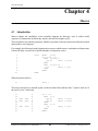
Introduction . . . . . . . . . . . . . . . . . . . . . . . . . . . . . . . . . . . . . . . . . . . . . . . . . . . . . . . . 63
Macro Definition . . . . . . . . . . . . . . . . . . . . . . . . . . . . . . . . . . . . . . . . . . . . . . . . . . . . 64
4.2.1
MACRO Directive . . . . . . . . . . . . . . . . . . . . . . . . . . . . . . . . . . . . . . . . . . 64
4.2.2
ENDM Directive . . . . . . . . . . . . . . . . . . . . . . . . . . . . . . . . . . . . . . . . . . . 65
4.2.3
EXITM Directive . . . . . . . . . . . . . . . . . . . . . . . . . . . . . . . . . . . . . . . . . . . 65
4.2.4
LOCAL Directive . . . . . . . . . . . . . . . . . . . . . . . . . . . . . . . . . . . . . . . . . . 65
4.2.5
Local Labels and Macros . . . . . . . . . . . . . . . . . . . . . . . . . . . . . . . . . . . . . 66
Formal Parameters . . . . . . . . . . . . . . . . . . . . . . . . . . . . . . . . . . . . . . . . . . . . . . . . . . . 66
Macro Invocation . . . . . . . . . . . . . . . . . . . . . . . . . . . . . . . . . . . . . . . . . . . . . . . . . . . . 67
4.4.1
Actual Values of Parameters . . . . . . . . . . . . . . . . . . . . . . . . . . . . . . . . . . 67
4.4.2
Token Pasting . . . . . . . . . . . . . . . . . . . . . . . . . . . . . . . . . . . . . . . . . . . . . 67
4.4.3
Quoting . . . . . . . . . . . . . . . . . . . . . . . . . . . . . . . . . . . . . . . . . . . . . . . . . . 67
Example Macros . . . . . . . . . . . . . . . . . . . . . . . . . . . . . . . . . . . . . . . . . . . . . . . . . . . . 68
4.5.1
Rename an Instruction . . . . . . . . . . . . . . . . . . . . . . . . . . . . . . . . . . . . . . . 68
4.5.2
Mix a Parameter with an Opcode . . . . . . . . . . . . . . . . . . . . . . . . . . . . . . 68
4.5.3
Assertion Checking . . . . . . . . . . . . . . . . . . . . . . . . . . . . . . . . . . . . . . . . . 69
Errors and Macros . . . . . . . . . . . . . . . . . . . . . . . . . . . . . . . . . . . . . . . . . . . . . . . . . . . 70
4.3
4.4
4.5
4.6
SASM Cross Assembler User’s Manual Rev. 1.3
4
© 2000 Ubicom, Inc. All rights reserved.
www.ubicom.com
Contents
Chapter 5
5.1
5.2
5.3
5.4
5.5
5.6
5.7
5.8
Assembler Output Files
Introduction . . . . . . . . . . . . . . . . . . . . . . . . . . . . . . . . . . . . . . . . . . . . . . . . . . . . . . . . 71
Object File (HEX or OBJ) . . . . . . . . . . . . . . . . . . . . . . . . . . . . . . . . . . . . . . . . . . . . . 71
Listing File (LST) . . . . . . . . . . . . . . . . . . . . . . . . . . . . . . . . . . . . . . . . . . . . . . . . . . . 71
Cross Reference Listing . . . . . . . . . . . . . . . . . . . . . . . . . . . . . . . . . . . . . . . . . . . . . . . 73
Symbol File (SYM) . . . . . . . . . . . . . . . . . . . . . . . . . . . . . . . . . . . . . . . . . . . . . . . . . . 73
Map File (MAP) . . . . . . . . . . . . . . . . . . . . . . . . . . . . . . . . . . . . . . . . . . . . . . . . . . . . . 74
Error File (ERR) . . . . . . . . . . . . . . . . . . . . . . . . . . . . . . . . . . . . . . . . . . . . . . . . . . . . 74
Error Messages . . . . . . . . . . . . . . . . . . . . . . . . . . . . . . . . . . . . . . . . . . . . . . . . . . . . . 74
Appendix A
A.1
A.2
A.3
A.4
A.5
A.6
A.7
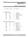
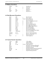
Assembler Output Files
Logical Operations . . . . . . . . . . . . . . . . . . . . . . . . . . . . . . . . . . . . . . . . . . . . . . . . . . . 75
Arithmetic and Shift Operations . . . . . . . . . . . . . . . . . . . . . . . . . . . . . . . . . . . . . . . . . 75
Bitwise Operations . . . . . . . . . . . . . . . . . . . . . . . . . . . . . . . . . . . . . . . . . . . . . . . . . . . 76
Data Movement Operations . . . . . . . . . . . . . . . . . . . . . . . . . . . . . . . . . . . . . . . . . . . . 76
Control Transfer Operations . . . . . . . . . . . . . . . . . . . . . . . . . . . . . . . . . . . . . . . . . . . . 76
System Control Operations . . . . . . . . . . . . . . . . . . . . . . . . . . . . . . . . . . . . . . . . . . . . . 77
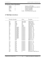
Multi-Byte Instructions. . . . . . . . . . . . . . . . . . . . . . . . . . . . . . . . . . . . . . . . . . . . . . . . 77
Appendix B Object File Format
B.1
General Information About All Formats . . . . . . . . . . . . . . . . . . . . . . . . . . . . . . . . . . 79
B.1.1
File register Address Map. . . . . . . . . . . . . . . . . . . . . . . . . . . . . . . . . . . . . 79
B.1.2
Program Memory Map . . . . . . . . . . . . . . . . . . . . . . . . . . . . . . . . . . . . . . . 79
B.1.3
ID String and FUSE Words . . . . . . . . . . . . . . . . . . . . . . . . . . . . . . . . . . . 80
B.1.4
Device Type Code . . . . . . . . . . . . . . . . . . . . . . . . . . . . . . . . . . . . . . . . . . 80
B.1.5
Frequency and Break . . . . . . . . . . . . . . . . . . . . . . . . . . . . . . . . . . . . . . . . 80
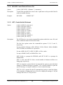
B.1.6
Sample Program . . . . . . . . . . . . . . . . . . . . . . . . . . . . . . . . . . . . . . . . . . . . 81
B.2
Intel HEX File Format . . . . . . . . . . . . . . . . . . . . . . . . . . . . . . . . . . . . . . . . . . . . . . . . 82
B.2.1
INHX8M: Merged 8-bit Intel Hex File Format . . . . . . . . . . . . . . . . . . . . 82
B.2.2
INHX16: 16-bit Intel Hex File Format . . . . . . . . . . . . . . . . . . . . . . . . . . . 83
B.2.3
INHX8S: Split 8-bit Intel Hex File Format . . . . . . . . . . . . . . . . . . . . . . . 83
B.3
Binary File Format . . . . . . . . . . . . . . . . . . . . . . . . . . . . . . . . . . . . . . . . . . . . . . . . . . . 84
B.4
IEEE-695 File Format. . . . . . . . . . . . . . . . . . . . . . . . . . . . . . . . . . . . . . . . . . . . . . . . . 84
B.4.1
Target Device . . . . . . . . . . . . . . . . . . . . . . . . . . . . . . . . . . . . . . . . . . . . . . 84
B.4.2
Symbols . . . . . . . . . . . . . . . . . . . . . . . . . . . . . . . . . . . . . . . . . . . . . . . . . . 84
B.4.3
SX Program Address Spaces . . . . . . . . . . . . . . . . . . . . . . . . . . . . . . . . . . 85
B.4.4
Assembly-Time Environment. . . . . . . . . . . . . . . . . . . . . . . . . . . . . . . . . . 85
B.4.5
Line Numbers . . . . . . . . . . . . . . . . . . . . . . . . . . . . . . . . . . . . . . . . . . . . . . 85
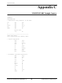
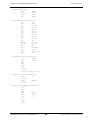
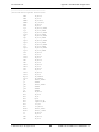
Appendix C SX52INST.SRC Sample Source
Appendix D Error Message
© 2000 Ubicom, Inc. All rights reserved.
5
SASM Cross Assembler User’s Manual Rev. 1.3
www.ubicom.com
© 2000 Ubicom, Inc. All rights reserved.
Contents
6
SASM Cross Assembler User’s Manual Rev. 1.3
www.ubicom.com
Contents
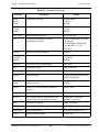
List of Tables
Table 1-1
Table 2-1
Table 3-1
Table 3-2
Table 3-3
Options Summary .......................................................................................................10
Constants Declaration .................................................................................................40
Assembler Directives ..................................................................................................47
FUSE/FUSEX Bit Settings for SX18/20/28AC ..........................................................50
FUSE/FUSEX Bit Settings for SX48/52BD ...............................................................52
© 2000 Ubicom, Inc. All rights reserved.
7
SX User’s Manual Rev. 3.1
Contents
SX User’s Manual Rev. 3.1
www.ubicom.com
8
© 2000 Ubicom, Inc. All rights reserved.
www.ubicom.com
Chapter 1
Overview
1.1
Introduction
This User's Manual describes the SASM Cross Assembler for the SX communications controllers from
Scenix.
The manual explains how to invoke and use SASM. Topics include program structure, directives,
macros and file outputs. A summary on the SX basic instruction set is also given.
SASM Cross Assembler is a software development tool that accepts the SX symbolic assembly
language as input and translates it into object codes under the MS-DOS operating system on the IBM
PC or compatible systems.
1.2
Main Features
•
Translates programs (source code) written in SX Assembly language to machine executable code
(object code) on IBM PC or compatibles running MS-DOS version 3.0 or higher.
•
Generates object code for SX communications controllers including the SX18/20/28AC, and
SX48/52BD devices using four different formats: three Intel hex formats (INHX8M, INHX16,
INHX8S) binary format, and IEEE695 format.
•
Provides MACRO and conditional assembly capabilities.
•
Supports Hex, Decimal (default) and Octal source and listing formats.
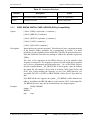
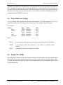
1.3
Invoking SASM
Use an editor of your choice to create an ASM source file. Assemble this source file by typing the
following at the command prompt of the directory where SASM.EXE resides:
SASM [options] file[.asm]
[Enter]
where file = source file name
SASM Cross Assembler User’s Manual Rev. 1.3
9
© 2000 Ubicom, Inc. All rights reserved.
Chapter 1 Overview
www.ubicom.com
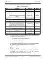
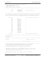
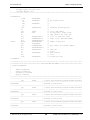
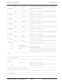
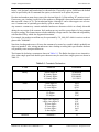
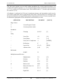
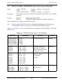
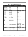
Tables 1-1 shows the summary of options specified at the command prompt.
Table 1-1 Options Summary
Opt
Arguments
Description
Default
/C
SX|PARALLAX
Compiler Mode
PARALLAX
Extensions for
various tool
environments
NONE
Output Format
INHX8M
/E
/F
[INHX8M|INHX8S|INHX16|INHX32|BIN16|
IEEE695]
/H or /?
Display Help Message
/I
Turn on case sensitivity
Symbols
Off
/L
NONE | PAGE | NOPAGE
Listing File
NOPAGE
/P
[SX18|SX18AC|PINS18|SX20|SX20AC|
PINS20|SX28|SX28AC|PINS28|SX48|
SX48AC|PINS48|SX52|SX52AC|PINS52|]
Processor Type
SX18AC
/Q
[message number]
Quiet a warning msg
None
/R
[HEX|BIN|DEC|OCT|D|B|O|H]
Radix
DEC
/T
[TABWIDTH]
Tab Width
8
/W
[0|1|2]
Warning Level
1
/Z
Disable path
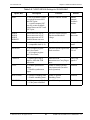
NOTES: 1.
2.
To eliminate comments (e.g. crossing page boundary) from the list files, set warning
to a higher level. For example, set /W to 2.
•
/W 0 will include all comments and warning errors.
•
/W 1 will include warning errors.
•
/W 2 will include errors only.
It is recommended to set the processor type inside the main program rather than on
the command line. That is, include the following line in the .ASM file:
DEVICE
OR
DEVICE
3.
SX18AC
PINS18
Version 1.45.5 or higher of SASM defaults to `/I /CPARALLAX /FINHX8M /
PSX18 /RDEC /T8 /W1 /LNOPAGE'. The `/F', `/L', `/P', `/Q', and `/R' options may
also be specified in the source file with the `LIST' directive.
SASM Cross Assembler User’s Manual Rev. 1.3
10
© 2000 Ubicom, Inc. All rights reserved.
Chapter 1 Overview
www.ubicom.com
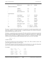
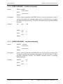
1.3.1
Compiler Mode
Command: /C
Arguments: SX|PARALLAX
Description The assembler can handle two sets of mnemonics. This option chooses the specific
collection of mnemonics to be recognized. It may take any of the values `SX', or
`PARALLAX'.
Default:
1.3.2
‘/C PARALLAX’
Extensions for Various Tool Environments
Command: /E
Arguments: NONE | NOHAU
Description `/E NOHAU' can be used to cause the format of the logged error messages to use `#'
characters to delimit the fields, and to write the error log to a file name `cmperr.log' in
the current directory regardless of the name of the source file.
Default:
1.3.3
‘/E NONE
Output Format
Command: /F
Arguments: [INHX8M|INHX8S|INHX16|INHX32|BIN16|IEEE695]
Description The assembler can generate a binary file, several formats of hex files, or an IEEE-695
format object file. This option chooses the output format. It may take any of the values
`BIN16', `INHX16', `INHX8M', `INHX8S', `INHX32', or `IEEE695'.
Default:
1.3.4
‘/F INHX8M’
Display Help Message
Command: /H or /?
Arguments:
Description Display the help screen and exit.
Default:
© 2000 Ubicom, Inc. All rights reserved.
11
SASM Cross Assembler User’s Manual Rev. 1.3
Chapter 1 Overview
1.3.5
www.ubicom.com
Case Independent Symbols
Command: /I
Arguments: Turn on case sensitivity
Description This option is “on” by default and there is no documented option to turn it “off”.
Default:
1.3.6
On
Listing File
Command: /L
Arguments: Use `/L NONE' to disable the listing.
Description This option takes a keyword indicating whether a listing file is desired, and whether it
has page headers and form feeds. Use `/L PAGE' to produce a listing with page headers
and form feeds. By default there are 55 total lines per page, which can be modified with
the LIST directive. Use `/L NOPAGE' to produce a listing a listing with no page headers
or form feeds.
Default:
1.3.7
`/L NOPAGE'
Target Processor
Command: /P
Arguments: [SX18|SX18AC|PINS18|SX20|SX20AC|PINS20|SX28|SX28AC|PINS28|SX48|
SX48AC|PINS48|SX52|SX52AC|PINS52|]
Description This option selects the default target processor, which may be over ridded by the
DEVICE directive. Choose one of `SX18', `SX18AC', `PINS18', `SX20', `SX20AC',
`PINS20', `SX28', `SX28AC', `PINS28', `SX48', `SX48AC', `PINS48', `SX52',
`SX52AC', or `PINS52'.
Default:
‘/P SX18AC’
SASM Cross Assembler User’s Manual Rev. 1.3
12
© 2000 Ubicom, Inc. All rights reserved.
Chapter 1 Overview
www.ubicom.com
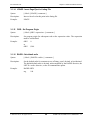
1.3.8
Quiet Message
Command: /Q
Arguments: message number
Description Individual warning and comment messages may be disabled (quieted) with this
command line option. Use this option multiple times to quiet more than one warning
message. The message number appears in the warning or comment, or can be found in
the appendix to this manual.
This option may be set within the assembly file with the Q= option of the LIST
directive. This may be more convenient when several messages are involved.
If the message number is negative, then those messages are enable if they are presently
quiet.
Note that the /W option supersedes the /Q option.
Default:
1.3.9
No messages are quiet by default.
Radix
Command: /R
Arguments: [HEX|BIN|DEC|OCT|D|B|O|H]
Description This option selects the default radix used to interpret numeric constants which do not
specify a radix. Choose one of `DEC', `BIN', `OCT', `HEX', `D', `B', `O', or `H'.
Default:
`/R DEC'
1.3.10 Default Tab Width
Command: /T
Arguments: [TABWIDTH]
Description This option sets the assumed width of a tab character, and may be set to any positive
integer less than 20.
Default:
`/T 8'
© 2000 Ubicom, Inc. All rights reserved.
13
SASM Cross Assembler User’s Manual Rev. 1.3
Chapter 1 Overview
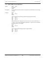
1.3.11
www.ubicom.com
Error Level
Command: /W
Arguments: [0|1|2]
Description This option controls the number of comments, warnings, and error messages which
appear. Set it to 0 for lots of output, 1 for warnings and errors only, or 2 for errors only.
Default:
`/W 1'
1.3.12 Disable Full Pathnames in .MAP File
Command: /Z
Arguments:
Description By default the fully-qualified pathname of each file will be stored in the .MAP file. This
command-line option forces only the filename without the path to be stored.
Default:
1.4
The full path to each file is stored.
Source Files
The source file is the file to be assembled. SASM assumes all source files to have .ASM extensions. If
not, the entire filename, including extension, has to be provided at the command line.
1.5
Output Files
SASM Assembler outputs different files with the following extensions:
HEX
- Intel 8-bit merged Hex file (*Default file format)
OBJ
- Binary object file if /F BIN is used
HXH/HXL
- Address/Data pairs for high-order and low-order 8 bits (only when INHX8S format
is selected as output)
LST
- Program listing file
SYM
- Symbol file used for defining watch variables and setting break point at label
address. Used for symbolic or source-level debugging.
MAP
- Map file used for source-level debugging
ERR
- Error message file
SXE
- IEEE695 output file format if /F IEEE695 option is used
SASM Cross Assembler User’s Manual Rev. 1.3
14
© 2000 Ubicom, Inc. All rights reserved.
www.ubicom.com
Chapter 2
Program Structure
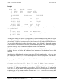
2.1
Source Program
The structure of a source program consists of one or more statements and comments. Each statement
can be a combination of mnemonics, directives, macros, symbols, expressions and/or constants.
Example of an assembly program:
;*****************************************************************************************
; Copyright © [11/21/1999] Ubicom, Inc. All rights reserved.
;
; Scenix, Inc. assumes no responsibility or liability for
; the use of this [product, application, software, any of these products].
; Ubicom conveys no license, implicitly or otherwise, under
; any intellectual property rights.
; Information contained in this publication regarding (e.g.: application,
; implementation) and the like is intended through suggestion only and may
; be superseded by updates. Ubicom makes no representation
; or warranties with respect to the accuracy or use of these information,
; or infringement of patents arising from such use or otherwise.
;*****************************************************************************************
;
; Filename: vpg_UART_1_04.src
;
; Authors:
Chris Fogelklou
;
Applications Engineer
;
Ubicom, Inc.
;
; Program Description:
;
;
Virtual Peripherals Guidelines:
;
Example source code, running at 50MHz, with just a transmit
;
and receive UART. The code implements UART in software for baud rates of
;
1200,2400,4800,9600,19200,57600 bps depending on the rate selected, it can
;
be selected to work at interrupt rate of 4.32us.
;
; Interface Pins:
;
;
rs232RxPin
equ
ra.2
;UART receive input
;
rs232TxPin
equ
ra.3
;UART transmit output
;
rts_pin
equ
ra.0
;UART 1 RTS input
;
cts_pin
equ
ra.1
;UART 1 CTS output
;
;*****************************************************************************************
SASM Cross Assembler User’s Manual Rev. 1.3
15
© 2000 Ubicom, Inc. All rights reserved.
Chapter 2 Program Structure
www.ubicom.com
;*****************************************************************************************
; Target SX
; Uncomment one of the following lines to choose the SX18AC,SX20AC,SX28AC,SX48BD, SX52BD.
;*****************************************************************************************
;SX18_20
;SX28AC
SX48_52
;*****************************************************************************************
; Assembler Used
; Uncomment the following line if using the Parallax SX-Key assembler. SASM assembler
; enabled by default.
;*****************************************************************************************
;SX_Key
;*****************************************************************************************
; Uncomment one of the following to run the uart vp at the required baud rate
;*****************************************************************************************
;baud1200
;baud rate of 1.2 Kbps
;baud2400
;baud4800
;baud rate of 4.8 Kbps
baud9600
;baud rate of 9.6 kbps
;baud1920
;baud rate of 19.2kbps
;baud5760
;baud rate of 57.6kbps
;*****************************************************************************************
;
Assembler directives
;
;
High speed external osc, turbo mode, 8-level stack, and extended option reg.
;
SX18/20/28 - 4 pages of program memory and 8 banks of RAM enabled by default.
;
SX48/52 - 8 pages of program memory and 16 banks of RAM enabled by default.
;*****************************************************************************************
IFDEF SX_Key
;SX-Key Directives
IFDEF SX18_20
device
ENDIF
;SX18AC or SX20AC device directives for SX-Key
SX18L,oschs2,turbo,stackx_optionx
IFDEF SX28AC
device
ENDIF
;SX28AC device directives for SX-Key
SX28L,oschs2,turbo,stackx_optionx
IFDEF SX48_52
device
oschs2
ENDIF
freq
50_000_000
ELSE
IFDEF SX18_20
device
;SX48/52/BD device directives for SX-Key
;SASM Directives
;SX18AC or SX20AC device directives for SASM
SX18,oschs2,turbo,stackx,optionx
SASM Cross Assembler User’s Manual Rev. 1.3
16
© 2000 Ubicom, Inc. All rights reserved.
Chapter 2 Program Structure
www.ubicom.com
ENDIF
IFDEF SX28AC
device
ENDIF
;SX28AC device directives for SASM
SX28,oschs2,turbo,stackx,optionx
IFDEF SX48_52
device SX52,oschs2
ENDIF
;SX48BD or SX52BD device directives for SASM
ENDIF
id
'1UART_VP’
reset resetEntry
;
; set reset vector
;*********************************************************************************
;--------------------------------------Macro's-----------------------------------; Macro: _bank
; Sets the bank appropriately for all revisions of SX.
;
; This is required since the bank instruction has only a 3-bit operand, it cannot
; be used to access all 16 banks of the SX48/52. FSR.7 (SX48/52bd production
; release) needs to be set appropriately, depending on the bank address being
; accessed. This macro fixes this.
;
; So, instead of using the bank instruction to switch between banks, use _bank
; instead.
;*********************************************************************************
_bank macro
noexpand
bank
IFDEF
IF
expand
setb
1
\1
SX48_52
\1 & %10000000
fsr.7
;SX48BD and SX52BD (production release) bank instruction
;modifies FSR bits 4,5 and 6. FSR.7 needs to be set by
;software.
noexpand
ELSE
expand
clrb
fsr.7
noexpand
ENDIF
ENDIF
endm
;*********************************************************************************
; Macro: _mode
; Sets the MODE register appropriately for all revisions of SX.
;
; This is required since the MODE (or MOV M,#) instruction has only a 4-bit operand.
; The SX18/20/28AC use only 4 bits of the MODE register, however the SX48/52BD have
; the added ability of reading or writing some of the MODE registers, and therefore
; use 5-bits of the MODE register. The MOV M,W instruction modifies all 8-bits of
; the MODE register, so this instruction must be used on the SX48/52BD to make sure
; the MODE register is written with the correct value. ; This macro fixes this.
© 2000 Ubicom, Inc. All rights reserved.
17
SASM Cross Assembler User’s Manual Rev. 1.3
Chapter 2 Program Structure
www.ubicom.com
;
; So, instead of using the MODE or MOV M,# instructions to load the M register, use
; _mode instead.
;*********************************************************************************
_mode
macro
1
noexpand
IFDEF SX48_52
expand
mov
w,#\1
mov
m,w
noexpand
ELSE
expand
mov
m,#\1
;loads the M register correctly for the SX48BD and SX52BD
;loads the M register correctly for the SX18AC, SX20AC
;and SX28AC
noexpand
ENDIF
endm
;*********************************************************************************
; INCP/DECP macros for incrementing/decrementing pointers to RAM
; used to compensate for incompatibilities between SX28AC and SX52BD
;*********************************************************************************
INCP macro 1
; Increments a pointer to RAM
inc
\1
IFNDEF SX48_52
setb \1.4
ENDIF
; If SX18 or SX28AC,keep bit 4 of the pointer = 1
; to jump from $1f to $30,etc
endm
DECP macro 1
IFDEF SX48_52
dec
\1
ELSE
clrb
\1.4
dec
\1
setb
\1.4
ENDIF
endm
; Decrements a pointer to RAM
;
;
;
;
If SX18 or SX28AC, forces rollover to next bank
if it rolls over. (skips banks with bit 4 = 0)
Eg: $30 ---> $20 ---> $1f ---> $1f
AND: $31 ---> $21 ---> $20 ---> $30
;*********************************************************************************
; Error generating macros
; Used to generate an error message if the label is intentionally moved into the
; second page.
; Use for lookup tables.
;*********************************************************************************
tableStart
macro
if $ & $100
ERROR
0
; Generates an error message if code that MUST be in
; the first half of a page is moved into the second half
'Must be located in the first half of a page.'
SASM Cross Assembler User’s Manual Rev. 1.3
18
© 2000 Ubicom, Inc. All rights reserved.
Chapter 2 Program Structure
www.ubicom.com
endif
endm
tableEnd
macro
0
if $ & $100
ERROR
endif
; Generates an error message if code that MUST be in
; the first half of a page is moved into the second half
'Must be located in the first half of a page.'
endm
;*****************************************************************************************
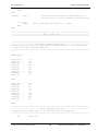
;------------------------------------Memory Organization---------------------------------;*****************************************************************************************
;*****************************************************************************************
;----------------------------Data Memory address definitions-----------------------------; These definitions ensure the proper address is used for banks 0 - 7 for 2K SX devices
; (SX18/20/28) and 4K SX devices (SX48/52).
;*****************************************************************************************
****
IFDEF SX48_52
global_org
bank0_org
bank1_org
bank2_org
bank3_org
bank4_org
bank5_org
bank6_org
bank7_org
=
=
=
=
=
=
=
=
=
$0A
$00
$10
$20
$30
$40
$50
$60
$70
=
=
=
=
=
=
=
=
=
$08
$10
$30
$50
$70
$90
$B0
$D0
$F0
ELSE
global_org
bank0_org
bank1_org
bank2_org
bank3_org
bank4_org
bank5_org
bank6_org
bank7_org
ENDIF
;*****************************************************************************************
;-------------------------------- Global Register definitions---------------------------; NOTE: Global data memory starts at $0A on SX48/52 and $08 on SX18/20/28.
;*****************************************************************************************
org
global_org
© 2000 Ubicom, Inc. All rights reserved.
19
SASM Cross Assembler User’s Manual Rev. 1.3
Chapter 2 Program Structure
www.ubicom.com
flags0
equ
global_org + 0
; stores bit-wise operators like flags
; and function-enabling bits (semaphores)
;-----------------------------VP: RS232 Receive-----------------------------------------rs232RxFlag equ
flags0.0;indicates the reception of a bit from the UART
isrTemp0
equ
global_org + 1
localTemp0
equ
global_org + 2
localTemp1
equ
global_org + 3
localTemp2
equ
global_org + 4
;
;
;
;
;
;
;
;
;
;
;
;
;
Interrupt Service Routine's temp register.
Don't use this register in the mainline.
temporary storage register
Used by first level of nesting
Never guaranteed to maintain data
temporary storage register
Used by second level of nesting
or when a routine needs more than one
temporary global register.
temporary storage register
Used by third level of nesting or by
main loop routines that need a loop
counter, etc.
;*****************************************************************************************
;--------------------------- RAM Bank Register definitions--------------------------------;*****************************************************************************************
;*********************************************************************************
; Bank 0
;*********************************************************************************
org
bank0
=
bank0_org
$
;*********************************************************************************
; Bank 1
;*********************************************************************************
org
bank1_org
bank1
rs232TxBank
rs232Txhigh
rs232Txlow
rs232Txcount
rs232Txdivide
rs232Txflag
=
=
ds
ds
ds
ds
ds
$
$
1
1
1
1
1
;UART bank
;hi byte to transmit
;low byte to transmit
;number of bits sent
;xmit timing (/16) counter
rs232RxBank
rs232Rxcount
rs232Rxdivide
rs232Rxbyte
string
rs232byte
hex
=
ds
ds
ds
ds
ds
ds
$
1
1
1
1
1
1
;number of bits received
;receive timing counter
;buffer for incoming byte
;used by send_string to store the address in memory
;used by serial routines
MultiplexBank
=
$
SASM Cross Assembler User’s Manual Rev. 1.3
20
© 2000 Ubicom, Inc. All rights reserved.
Chapter 2 Program Structure
www.ubicom.com
isrMultiplex
ds
1
;*********************************************************************************
; Bank 2
;*********************************************************************************
org
bank2
=
bank2_org
$
;*********************************************************************************
; Bank 3
;*********************************************************************************
org
bank3
=
bank3_org
$
;*********************************************************************************
; Bank 4
;*********************************************************************************
org
bank4
=
bank4_org
$
;*********************************************************************************
; Bank 5
;*********************************************************************************
org
bank5
=
bank5_org
$
;*********************************************************************************
; Bank 6
;*********************************************************************************
org
bank6
=
bank6_org
$
;*********************************************************************************
; Bank 7
;*********************************************************************************
org
bank7
=
bank7_org
$
IFDEF SX48_52
;*********************************************************************************
; Bank 8
© 2000 Ubicom, Inc. All rights reserved.
21
SASM Cross Assembler User’s Manual Rev. 1.3
Chapter 2 Program Structure
www.ubicom.com
;*********************************************************************************
bank8
org
$80
=
$
;bank 8 address on SX52
;*********************************************************************************
; Bank 9
;*********************************************************************************
bank9
org
$90
=
$
;bank 9 address on SX52
;*********************************************************************************
; Bank A
;*********************************************************************************
bankA
org
$A0
=
$
;bank A address on SX52
;*********************************************************************************
; Bank B
;*********************************************************************************
bankB
org
$B0
=
$
;bank B address on SX52
;*********************************************************************************
; Bank C
;*********************************************************************************
bankC
org
$C0
=
$
;bank C address on SX52
;*********************************************************************************
; Bank D
;*********************************************************************************
bankD
org
$D0
=
$
;bank D address on SX52
;*********************************************************************************
; Bank E
;*********************************************************************************
bankE
org
$E0
=
$
;bank E address on SX52
SASM Cross Assembler User’s Manual Rev. 1.3
22
© 2000 Ubicom, Inc. All rights reserved.
Chapter 2 Program Structure
www.ubicom.com
;*********************************************************************************
; Bank F
;*********************************************************************************
bankF
org
$F0
=
$
;bank F address on SX52
ENDIF
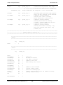
;*****************************************************************************************
;---------------------------------- Port Assignment-------------------------------------;*****************************************************************************************
RA_latch
RA_DDIR
RA_LVL
RA_PLP
equ
equ
equ
equ
%00001000
%11110111
%00000000
%00001100
;SX18/20/28/48/52
;SX18/20/28/48/52
;SX18/20/28/48/52
;SX18/20/28/48/52
port
port
port
port
RB_latch
equ
%00000000
port B latch init;initial value after
RB_DDIR
RB_ST
RB_LVL
RB_PLP
equ
equ
equ
equ
%11111111
%11111111
%00000000
%00000000
;SX18/20/28/48/52
;reset
;SX18/20/28/48/52
;SX18/20/28/48/52
;SX18/20/28/48/52
;SX18/20/28/48/52
RC_latch
equ
%00000000
RC_DDIR
RC_ST
RC_LVL
RC_PLP
equ
equ
equ
equ
%11111111
%11111111
%00000000
%00000000
;SX18/20/28/48/52
;reset
;SX18/20/28/48/52
;SX18/20/28/48/52
;SX18/20/28/48/52
;SX18/20/28/48/52
RD_latch
RD_DDIR
RD_ST
RD_LVL
RD_PLP
equ
equ
equ
equ
equ
%00000000
%11111111
%11111111
%00000000
%00000000
;SX48/52
;SX48/52
;SX48/52
;SX48/52
;SX48/52
port
port
port
port
port
D
D
D
D
D
latch init;initial value after reset
DDIR value;0=Output,1=Input
ST value;0=Enable,1=Disable
LVL value;0=CMOS,1=TTL
PLP value;0=Enable,1=Disable
RE_latch
RE_DDIR
RE_ST
RE_LVL
RE_PLP
equ
equ
equ
equ
equ
%00000000
%11111111
%11111111
%00000000
%00000000
;SX48/52
;SX48/52
;SX48/52
;SX48/52
;SX48/52
port
port
port
port
port
E
E
E
E
E
latch init;initial value after reset
DDIR value;0=Output,1=Input
ST value;0=Enable,1=Disable
LVL value;0=CMOS,1=TTL
PLP value;0=Enable,1=Disable
port
port
port
port
A
A
A
A
B
B
B
B
latch init
DDIR value
LVL value
PLP value
DDIR value;0=Output,1=Input
ST value;0=Enable,1=Disable
LVL value;0=CMOS,1=TTL
PLP value;0=Enable,1=Disable
port C latch init;initial value after
port
port
port
port
C
C
C
C
DDIR value;0=Output,1=Input
ST value;0=Enable,1=Disable
LVL value;0=CMOS,1=TTL
PLP value;0=Enable,1=Disable
IFDEF SX48_52
ENDIF
;*****************************************************************************************
;--------------------------------- Pin Definitions---------------------------------------;*****************************************************************************************
rs232RTSpin
rs232CTSpin
rs232Rxpin
equ
equ
equ
ra.0
ra.1
ra.2
© 2000 Ubicom, Inc. All rights reserved.
;UART RTS input
;UART CTS output
;UART receive input
23
SASM Cross Assembler User’s Manual Rev. 1.3
Chapter 2 Program Structure
rs232Txpin
equ
ra.3
www.ubicom.com
;UART transmit output
;*****************************************************************************************
;---------------------------------- Program constants------------------------------------;*****************************************************************************************
_enter
_linefeed
equ
equ
13
10
; ASCII value for carriage return
; ASCII value for a line feed
;*****************************************************************************************
;
UART Constants values
;*****************************************************************************************
intPeriod
= 217
UARTfs
= 230400
Num
= 4
IFDEF baud1200
UARTBaud
ENDIF
= 1200
IFDEF baud2400
UARTBaud
ENDIF
= 2400
IFDEF baud4800
UARTBaud
ENDIF
= 4800
IFDEF baud9600
UARTBaud
ENDIF
= 9600
IFDEF baud1920
UARTBaud
ENDIF
= 19200
IFDEF baud5760
UARTBaud
ENDIF
= 57600
UARTDivide
UARTStDelay
= (UARTfs/(UARTBaud*Num))
= UARTDivide +(UARTDivide/2)+1
IFDEF SX48_52
;*****************************************************************************************
; SX48BD/52BD Mode addresses
; *On SX48BD/52BD, most registers addressed via mode are read and write, with the
; exception of CMP and WKPND which do an exchange with W.
;*****************************************************************************************
;---------------------------------- Timer (read) addresses--------------------------------
SASM Cross Assembler User’s Manual Rev. 1.3
24
© 2000 Ubicom, Inc. All rights reserved.
Chapter 2 Program Structure
www.ubicom.com
TCPL_R
TCPH_R
TR2CML_R
TR2CMH_R
TR1CML_R
TR1CMH_R
TCNTB_R
TCNTA_R
equ
equ
equ
equ
equ
equ
equ
equ
$00
$01
$02
$03
$04
$05
$06
$07
;Read
;Read
;Read
;Read
;Read
;Read
;Read
;Read
Timer
Timer
Timer
Timer
Timer
Timer
Timer
Timer
Capture register
Capture register
R2 low byte
R2 high byte
R1 low byte
R1 high byte
control register
control register
low byte
high byte
B
A
;---------------------------------- Exchange addresses-----------------------------------CMP
WKPND
equ
equ
$08
$09
;Exchange Comparator enable/status register with W
;Exchange MIWU/RB Interrupts pending with W
;----------------------------------port setup (read) addresses---------------------------WKED_R
WKEN_R
ST_R
LVL_R
PLP_R
DDIR_R
equ
equ
equ
equ
equ
equ
$0A
$0B
$0C
$0D
$0E
$0F
;Read
;Read
;Read
;Read
;Read
;Read
MIWU/RB Interrupt edge setup,
MIWU/RB Interrupt edge setup,
Port Schmitt Trigger setup, 0
Port Schmitt Trigger setup, 0
Port Schmitt Trigger setup, 0
Port Direction
1
0
=
=
=
= falling,
= enabled,
enabled, 1
enabled, 1
enabled, 1
0
1
=
=
=
= rising
= disabled
disabled
disabled
disabled
;-----------------------------------Timer (write) addresses------------------------------CLR_TMR
TR2CML_W
TR2CMH_W
TR1CML_W
TR1CMH_W
TCNTB_W
TCNTA_W
equ
equ
equ
equ
equ
equ
equ
$10
$12
$13
$14
$15
$16
$17
;Resets 16-bit Timer
;Write Timer R2 low byte
;Write Timer R2 high byte
;Write Timer R1 low byte
;Write Timer R1 high byte
;Write Timer control register B
;Write Timer control register A
;-------------------------------------Port setup (write) addresses-----------------------WKED_W
WKEN_W
ST_W
LVL_W
PLP_W
DDIR_W
equ
equ
equ
equ
equ
equ
$1A
$1B
$1C
$1D
$1E
$1F
;Write
;Write
;Write
;Write
;Write
;Write
MIWU/RB Interrupt edge setup,
MIWU/RB Interrupt edge setup,
Port Schmitt Trigger setup, 0
Port Schmitt Trigger setup, 0
Port Schmitt Trigger setup, 0
Port Direction
1
0
=
=
=
= falling,
= enabled,
enabled, 1
enabled, 1
enabled, 1
0
1
=
=
=
= rising
= disabled
disabled
disabled
disabled
ELSE
;*****************************************************************************************
; SX18AC/20AC/28AC Mode addresses
; *On SX18/20/28, all registers addressed via mode are write only, with the exception of
; CMP and WKPND which do an exchange with W.
;*****************************************************************************************
;------------------------------------------Exchange addresses----------------------------CMP
WKPND
equ
equ
$08
$09
;Exchange Comparator enable/status register with W
;Exchange MIWU/RB Interrupts pending with W
© 2000 Ubicom, Inc. All rights reserved.
25
SASM Cross Assembler User’s Manual Rev. 1.3
Chapter 2 Program Structure
www.ubicom.com
;-----------------------------------------Port setup (read) addresses--------------------WKED_W
WKEN_W
ST_W
LVL_W
PLP_W
DDIR_W
equ
equ
equ
equ
equ
equ
$0A
$0B
$0C
$0D
$0E
$0F
;Write
;Write
;Write
;Write
;Write
;Write
MIWU/RB Interrupt edge setup,
MIWU/RB Interrupt edge setup,
Port Schmitt Trigger setup, 0
Port Schmitt Trigger setup, 0
Port Schmitt Trigger setup, 0
Port Direction
1
0
=
=
=
= falling,
= enabled,
enabled, 1
enabled, 1
enabled, 1
0
1
=
=
=
= rising
= disabled
disabled
disabled
disabled
ENDIF
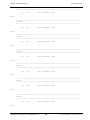
;*****************************************************************************************
;----------------------------------------------Program memory ORG defines----------------;*****************************************************************************************
INTERRUPT_ORG
RESETENTRY_ORG
SUBROUTINES_ORG
STRINGS_ORG
PAGE3_ORG
MAINPROGRAM_ORG
equ
equ
equ
equ
equ
equ
$0
$1FB
$200
$300
$400
$600
;
;
;
;
;
;
Interrupt must always start at location zero
The program will jump here on reset
The subroutines are in this location
The strings are in the location $300
Page 3 is empty
The main program is in the last page of program memory
;*****************************************************************************************
org
INTERRUPT_ORG
; First location in program memory.
;*****************************************************************************************
;*****************************************************************************************
;--------------------------------------------Interrupt Service Routine-------------------; Note 1: The interrupt code must always originate at address $0.
;
Interrupt Frequency = (Cycle Frequency / -(retiw value))
;
For example: With a retiw value of -217 and an oscillator frequency
;
of 50MHz, this code runs every 4.32us.
; Note 2: Mode Register 'M' is not saved in SX 28 but saved in SX 52 when an Interrupt
;
occurs. If the code is to run on a SX 28 and 'M' register is used in the ISR,
;
then the 'M' register has to be saved at the Start of ISR and restored at the
;
End of ISR.
;*****************************************************************************************
org
interrupt
$0
;3
;*****************************************************************************************
; Interrupt
; Interrupt Frequency = (Cycle Frequency / -(retiw value)) For example:
; With a retiw value of -217 and an oscillator frequency of 50MHz, this code runs
; every 4.32us.
;*****************************************************************************************
;*****************************************************************************************
;--------------------------------------------VP:VP Multitasker---------------------------; Virtual Peripheral Multitasker : up to 16 individual threads, each running at the
; (interrupt rate/16). Change them below:
; Input variable(s): is rmultiplex: variable used to choose threads
SASM Cross Assembler User’s Manual Rev. 1.3
26
© 2000 Ubicom, Inc. All rights reserved.
Chapter 2 Program Structure
www.ubicom.com
; Output variable(s): None, executes the next thread
; Variable(s) affected: isrmultiplex
; Flag(s) affected: None
; Program Cycles: 9 cycles (turbo mode)
;*****************************************************************************************
_bank
inc
mov
Multiplexbank
isrMultiplex
w,isrMultiplex
;
; toggle interrupt rate
;
;*****************************************************************************************
; The code between the tableStart and tableEnd statements MUST be completely within the first
; half of a page. The routines it is jumping to must be in the same page as this table.
;*****************************************************************************************
tableStart
jmp
jmp
jmp
jmp
jmp
jmp
jmp
jmp
jmp
jmp
jmp
jmp
jmp
jmp
jmp
jmp
jmp
tableEnd
; Start all tables with this macro
;
;
;
;
;
;
;
;
;
;
;
;
;
;
;
;
;
; End all tables with this macro.
pc+w
isrThread1
isrThread2
isrThread3
isrThread4
isrThread1
isrThread5
isrThread6
isrThread7
isrThread1
isrThread8
isrThread9
isrThread10
isrThread1
isrThread11
isrThread12
isrThread13
;*****************************************************************************************
;VP: VP Multitasker
; ISR TASKS
;*****************************************************************************************
isrThread1
; Serviced at ISR rate/4
;---------------------------------------------VP: RS232 Transmit-------------------------;*****************************************************************************************
; Virtual Peripheral: Universal Asynchronous Receiver Transmitter (UART)
; These routines send and receive RS232 serial data, and are currently
; configured (though modifications can be made) for the popular
; "No parity-checking, 8 data bit, 1 stop bit" (N,8,1) data format.
;
; RECEIVING: The rs232Rxflag is set high whenever a valid byte of data has been
; received and it is the calling routine's responsibility to reset this flag
; once the incoming data has been collected.
;
; TRANSMITTING: The transmit routine requires the data to be inverted
© 2000 Ubicom, Inc. All rights reserved.
27
SASM Cross Assembler User’s Manual Rev. 1.3
Chapter 2 Program Structure
www.ubicom.com
; and loaded (rs232Txhigh+rs232Txlow) register pair (with the inverted 8 data bits
; stored in rs232Txhigh and rs232Txlow bit 7 set high to act as a start bit). Then
; the number of bits ready for transmission (10=1 start + 8 data + 1 stop)
; must be loaded into the rs232Txcount register. As soon as this latter is done,
; the transmit routine immediately begins sending the data.
; This routine has a varying execution rate and therefore should always be
; placed after any timing-critical virtual peripherals such as timers,
; adcs, pwms, etc.
; Note: The transmit and receive routines are independent and either may be
;
removed, if not needed, to reduce execution time and memory usage,
;
as long as the initial "BANK serial" (common) instruction is kept.
;
Input variable(s) : rs232Txlow (only high bit used), rs232Txhigh, rs232Txcount
;
Output variable(s) : rs232Rxflag, rs232Rxbyte
;
Variable(s) affected : rs232Txdivide, rs232Rxdivide, rs232Rxcount
;
Flag(s) affected : rs232Rxflag
;
Variable(s) affected : Txdivide
;
Program cycles: 17 worst case
;
Variable Length? Yes.
;*****************************************************************************************
rs232Transmit
:txbit
_bank
rs232TxBank
;2 switch to serial register bank
decsz
jmp
mov
mov
test
snz
jmp
rs232Txdivide
:rs232TxOut
w,#UARTDivide
rs232Txdivide,w
rs232Txcount
:rs232TxOut
;1 only execute the transmit routine
;1
;1 load UART baud rate (50MHz)
;1
;1 are we sending?
;1
;1
rs232Txhigh
rs232Txlow
rs232Txcount
rs232Txlow.6
rs232TxPin
rs232Txlow.6
rs232TxPin
;1 yes, ready stop bit
;1 and shift to next bit
;1
;1 decrement bit counter
;1 output next bit
;1
;1
;1,17
clc
rr
rr
dec
snb
clrb
sb
setb
:rs232TxOut
;*****************************************************************************************
;----------------------------------------VP: RS232 Receive-------------------------------; Virtual Peripheral: Universal Asynchronous Receiver Transmitter (UART)
; These routines send and receive RS232 serial data, and are currently
; configured (though modifications can be made) for the popular
; "No parity-checking, 8 data bit, 1 stop bit" (N,8,1) data format.
; RECEIVING: The rx_flag is set high whenever a valid byte of data has been
; received and it is the calling routine's responsibility to reset this flag
; once the incoming data has been collected.
;
Output variable(s) : rx_flag, rx_byte
;
Variable(s) affected : tx_divide, rx_divide, rx_count
;
Flag(s) affected : rx_flag
SASM Cross Assembler User’s Manual Rev. 1.3
28
© 2000 Ubicom, Inc. All rights reserved.
Chapter 2 Program Structure
www.ubicom.com
;
Program cycles: 23 worst case
;
Variable Length? Yes.
;*****************************************************************************************
rs232Receive
:rxbit
_bank
sb
clc
snb
stc
test
sz
jmp
mov
sc
mov
mov
mov
decsz
jmp
mov
mov
dec
sz
rr
snz
setb
rs232RxBank
rs232RxPin
;2
;1 get current rx bit
;1
;1
;1
;1 currently receiving byte?
;1
;1 if so, jump ahead
;1 in case start, ready 9 bits
;1 skip ahead if not start bit
;1 it is, so renew bit count
;1 ready 1.5 bit periods (50MHz)
;1
;1 middle of next bit?
;1
;1 yes, ready 1 bit period (50MHz)
;1
;1 last bit?
;1 if not
;1 then save bit
;1 if so,
;1,23 then set flag
rs232RxPin
rs232Rxcount
:rxbit
w,#9
rs232Rxcount,w
w,#UARTStDelay
rs232RxDivide,w
rs232Rxdivide
:rs232RxOut
w,#UARTDivide
rs232Rxdivide,w
rs232Rxcount
rs232Rxbyte
rs232RxFlag
:rs232RxOut
;*****************************************************************************************
;===================================== PUT YOUR OWN VPs HERE==============================
; Virtual Peripheral:
;
;
Input variable(s):
;
Output variable(s):
;
Variable(s) affected:
;
Flag(s) affected:
;*****************************************************************************************
;----------------------------------------------------------------------------------------jmp
isrOut
; 7 cycles until mainline program resumes execution
;----------------------------------------------------------------------------------------isrThread2
; Serviced at ISR rate/16
;----------------------------------------------------------------------------------------jmp
isrOut
; 7 cycles until mainline program resumes execution
;----------------------------------------------------------------------------------------isrThread3
; Serviced at ISR rate/16
;----------------------------------------------------------------------------------------jmp
isrOut
; 7 cycles until mainline program resumes execution
;----------------------------------------------------------------------------------------isrThread4
; Serviced at ISR rate/16
;----------------------------------------------------------------------------------------jmp
isrOut
; 7 cycles until mainline program resumes execution
;----------------------------------------------------------------------------------------isrThread5
; Serviced at ISR rate/16
;-----------------------------------------------------------------------------------------
© 2000 Ubicom, Inc. All rights reserved.
29
SASM Cross Assembler User’s Manual Rev. 1.3
Chapter 2 Program Structure
www.ubicom.com
jmp
isrOut
; 7 cycles until mainline program resumes execution
;----------------------------------------------------------------------------------------isrThread6
; Serviced at ISR rate/16
;----------------------------------------------------------------------------------------jmp
isrOut
; 7 cycles until mainline program resumes execution
;----------------------------------------------------------------------------------------isrThread7
; Serviced at ISR rate/16
;----------------------------------------------------------------------------------------jmp
isrOut
; 7 cycles until mainline program resumes execution
;----------------------------------------------------------------------------------------isrThread8
; Serviced at ISR rate/16
;----------------------------------------------------------------------------------------jmp
isrOut
; 7 cycles until mainline program resumes execution
;----------------------------------------------------------------------------------------isrThread9
; Serviced at ISR rate/16
;----------------------------------------------------------------------------------------jmp
isrOut
; 7 cycles until mainline program resumes execution
;----------------------------------------------------------------------------------------isrThread10
; Serviced at ISR rate/16
;----------------------------------------------------------------------------------------jmp
isrOut
; 7 cycles until mainline program resumes execution
;----------------------------------------------------------------------------------------isrThread11
; Serviced at ISR rate/16
;----------------------------------------------------------------------------------------jmp
isrOut
; 7 cycles until mainline program resumes execution
;----------------------------------------------------------------------------------------isrThread12
; Serviced at ISR rate/16
jmp
isrOut
; 7 cycles until mainline program resumes execution
;----------------------------------------------------------------------------------------isrThread13
; Serviced at ISR rate/16
; This thread must reload the isrMultiplex register
_bank
Multiplexbank
mov
isrMultiplex,#255
; reload isrMultiplex so isrThread1 will be run on
; the next interrupt.
jmp
isrOut
; 7 cycles until mainline program resumes execution
; This thread must reload the isrMultiplex register
; since it is the last one to run in a rotation.
;----------------------------------------------------------------------------------------isrOut
;*****************************************************************************************
; Set Interrupt Rate
;*****************************************************************************************
isrend
mov
w,#-intperiod
retiw
;refresh RTCC on return
;(RTCC = 217-no of instructions executed in the ISR)
;return from the interrupt
;*****************************************************************************************
; End of the Interrupt Service Routine
;*****************************************************************************************
;*****************************************************************************************
; RESET VECTOR
;*****************************************************************************************
SASM Cross Assembler User’s Manual Rev. 1.3
30
© 2000 Ubicom, Inc. All rights reserved.
Chapter 2 Program Structure
www.ubicom.com
;*****************************************************************************************
;----------------------------------------Reset Entry-------------------------------------;*****************************************************************************************
org
RESETENTRY_ORG
resetEntry
; Program starts here on power-up
page
jmp
_resetEntry
_resetEntry
;*****************************************************************************************
;-----------------------------------------UART Subroutines-------------------------------;*****************************************************************************************
org
SUBROUTINES_ORG
;*****************************************************************************************
;
Function
: getbyte
;
INPUTS
: NONE
;
OUTPUTS
: Received byte in rs232Rxbyte
;
Get byte via serial port and echo it back to the serial port
;*****************************************************************************************
getbyte
jnb
clrb
_bank
mov
rs232RxFlag,$
rs232RxFlag
rs232RxBank
; wait till byte is received
; reset the receive flag
; switch to rs232 bank
rs232byte,rs232Rxbyte
; store byte (copy using W)
retp
;*****************************************************************************************
;
Function
: sendbyte
;
INPUTS
: 'w' - the byte to be sent via RS-232
;
OUTPUTS
: Outputs The byte via RS-232
;
Send byte via serial port
;*****************************************************************************************
sendbyte
mov
_bank
localTemp0,w
rs232TxBank
:wait
test
sz
jmp
rs232Txcount
; wait for not busy
:wait
;
w
rs232Txhigh,w
rs232Txlow.7
w,#10
rs232Txcount,w
;
;
;
;
not
mov
setb
mov
mov
retp
ready bits (inverse logic)
store data byte
set up start bit
1 start + 8 data + 1 stop bit
; leave and fix page bits
;*****************************************************************************************
;
Function
: sendstring
© 2000 Ubicom, Inc. All rights reserved.
31
SASM Cross Assembler User’s Manual Rev. 1.3
Chapter 2 Program Structure
www.ubicom.com
;
Care should be taken that the srings are located within program
;
memory locations $300-$3ff as the area
;
INPUTS
: 'w' -the address of a null-terminated string in program memory
;
OUTPUTS
: Outputs the string via RS-232
;
Send string pointed to by address in W register
;*****************************************************************************************
sendstring
_bank
mov
rs232TxBank
localTemp1,w
mov
mov
mov
iread
test
snz
jmp
call
_bank
inc
jmp
w,#STRINGS_ORG>>8
m,w
w,localTemp1
mov
mov
retp
w,#$1F
m,w
; store string address
:loop
:out
; with indirect addressing
;
;
;
;
;
;
w
:out
sendbyte
rs232TxBank
localTemp1
:loop
read next string character
using the mode register
are we at the last char?
if not=0, skip ahead
yes, leave & fix page bits
not 0, so send character
; point to next character
; loop until done
; reset the mode register
;*****************************************************************************************
;
Function
: uppercase
;
INPUTS
: byte - the byte to be converted
;
OUTPUTS
: byte - converted byte
;
Convert byte to uppercase.
;*****************************************************************************************
uppercase
mov
mov
sc
retp
mov
sub
retp
w,#'a'
w,rs232byte-w
;if byte is lowercase, then skip ahead
w,#'a'-'A'
rs232byte,w
;change byte to uppercase
;leave and fix page bits
;*****************************************************************************************
;
Function
: sendhex
;
INPUTS
: 'w' - the byte to be output
;
OUTPUTS
: Outputs the hex byte via RS-232
;
Output a hex number
;*****************************************************************************************
sendhex
mov
swap
and
call
call
mov
and
localTemp1,w
wreg
w,#$0f
hextable
sendbyte
w,localTemp1
w,#$0f
SASM Cross Assembler User’s Manual Rev. 1.3
32
© 2000 Ubicom, Inc. All rights reserved.
Chapter 2 Program Structure
www.ubicom.com
call
call
retp
hextable
sendbyte
;*****************************************************************************************
;
Function
: gethex
;
Inputs
: None
;
OUTPUTS
: Received HEX value is in 'hex' register.
;
This routine returns with an 8-bit value in the W and in the hex
;
register. It accepts a hex number from the terminal screen and
;
returns. Remember to write a prompt to the screen before calling get_hex
;*****************************************************************************************
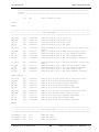
gethex
_bank
mov
call
call
mov
call
swap
mov
mov
rs232RxBank
w,#_enterhex
@sendstring
:getvalidhex
w,rs232byte
sendbyte
localTemp2
w,localTemp2
hex,w
;2
call
mov
call
mov
and
or
mov
retp
:getvalidhex
w,rs232byte
sendbyte
w,localTemp2
w,#$0f
w,hex
hex,w
clr
jnb
clrb
mov
call
localTemp2
rs232Rxflag,$
rs232Rxflag
rs232byte,rs232Rxbyte
uppercase
mov
call
xor
snz
ret
inc
jb
jmp
ret
w,localTemp2
hextable
w,rs232byte
; send the received (good) byte
; put the nibble in the upper nibble
; of hex register
; send the second received byte
:getvalidhex
:gh1
:loop
hextable
add
retw
retw
retw
retw
retw
; get a byte from the terminal
; uppercase it.
; get the value at temp (index)
; compare it to the received byte
localTemp2
localTemp2.4,:gh1
:loop
; if they are equal, we have the
; upper nibble. Continue if not.
pc,w
'0'
'1'
'2'
'3'
'4'
© 2000 Ubicom, Inc. All rights reserved.
33
SASM Cross Assembler User’s Manual Rev. 1.3
Chapter 2 Program Structure
retw
retw
retw
retw
retw
retw
retw
retw
retw
retw
retw
www.ubicom.com
'5'
'6'
'7'
'8'
'9'
'A'
'B'
'C'
'D'
'E'
'F'
;*****************************************************************************************
org
STRINGS_ORG
; This label defines where strings are kept in program space.
; all the following strings must be within the same half page of
; the program memory for send string to work, and they must be
; preceded by this label.
;*****************************************************************************************
;*****************************************************************************************
;---------------------------------------String Data--------------------------------------;*****************************************************************************************
;VP: RS232 Transmit
_hello
_hitSpace
_enterhex
org
dw
dw
dw
13,10,'Yup, The UART works!!!',0
13,10,'Hit Space...',0
13,10,'Enter Hex Value',0
PAGE3_ORG
jmp
$
;*****************************************************************************************
;---------------------------------------- Main Program ----------------------------------;
Program execution begins here on power-up or after a reset
;*****************************************************************************************
org
MAINPROGRAM_ORG
_resetEntry
;*****************************************************************************************
;---------------------------- Initialize all port configuration -------------------------;*****************************************************************************************
_mode
mov
mov
mov
mov
IFDEF SX48_52
mov
mov
mov
mov
ST_W
w,#RB_ST
!rb,w
w,#RC_ST
!rc,w
;point MODE to write ST register
;Setup RB Schmitt Trigger, 0 = enabled, 1 = disabled
w,#RD_ST
!rd,w
w,#RE_ST
!re,w
;Setup RD Schmitt Trigger, 0 = enabled, 1 = disabled
SASM Cross Assembler User’s Manual Rev. 1.3
;Setup RC Schmitt Trigger, 0 = enabled, 1 = disabled
;Setup RE Schmitt Trigger, 0 = enabled, 1 = disabled
34
© 2000 Ubicom, Inc. All rights reserved.
Chapter 2 Program Structure
www.ubicom.com
ENDIF
_mode
mov
mov
mov
LVL_W
w,#RA_LVL
!ra,w
w,#RB_LVL
mov
mov
mov
IFDEF SX48_52
mov
mov
mov
mov
ENDIF
_mode
mov
mov
mov
mov
mov
mov
IFDEF SX48_52
mov
mov
mov
mov
ENDIF
_mode
mov
mov
mov
mov
mov
mov
IFDEF SX48_52
mov
mov
mov
mov
ENDIF
mov
mov
mov
mov
mov
mov
IFDEF SX48_52
mov
mov
mov
mov
ENDIF
!rb,w
w,#RC_LVL
!rc,w
;point MODE to write LVL register
;Setup RA CMOS or TTL levels, 1 = TTL, 0 = CMOS
;Setup RB CMOS or TTL levels, 1 = TTL, 0 = CMOS,0,1
;= TTL, 2..7 = CMOS
;Setup RC CMOS or TTL levels, 1 = TTL, 0 = CMOS
w,#RD_LVL
!rd,w
w,#RE_LVL
!re,w
;Setup RD CMOS or TTL levels, 1 = TTL, 0 = CMOS
PLP_W
w,#RA_PLP
!ra,w
w,#RB_PLP
!rb,w
w,#RC_PLP
!rc,w
;point MODE to write PLP register
;Setup RA Weak Pull-up, 0 = enabled, 1 = disabled
w,#RD_PLP
!rd,w
w,#RE_PLP
!re,w
;Setup RD Weak Pull-up, 0 = enabled, 1 = disabled
DDIR_W
w,#RA_DDIR
!ra,w
w,#RB_DDIR
!rb,w
w,#RC_DDIR
!rc,w
;point MODE to write DDIR register
;Setup RA Direction register, 0 = output, 1 = input
w,#RD_DDIR
!rd,w
w,#RE_DDIR
!re,w
;Setup RD Direction register, 0 = output, 1 = input
w,#RA_latch
ra,w
w,#RB_latch
rb,w
w,#RC_latch
rc,w
;Initialize RA data latch
w,#RD_latch
rd,w
w,#RE_latch
re,w
;Setup RE CMOS or TTL levels, 1 = TTL, 0 = CMOS
;Setup RB Weak Pull-up, 0 = enabled, 1 = disabled
;Setup RC Weak Pull-up, 0 = enabled, 1 = disabled
;Setup RE Weak Pull-up, 0 = enabled, 1 = disabled
;Setup RB Direction register, 0 = output, 1 = input
;Setup RC Direction register, 0 = output, 1 = input
;Setup RE Direction register, 0 = output, 1 = input
;Initialize RB data latch
;Initialize RC data latch
;Initialize RD data latch
;Initialize RE data latch
;*****************************************************************************************
;------------------------------- Clear all Data RAM locations ----------------------------
© 2000 Ubicom, Inc. All rights reserved.
35
SASM Cross Assembler User’s Manual Rev. 1.3
Chapter 2 Program Structure
www.ubicom.com
;*****************************************************************************************
IFDEF SX48_52
:zeroRamclr
mov
mov
ind
incsz
jmp
w,#$0a
fsr,w
_bank
clr
clr
clr
clr
clr
clr
clr
clr
clr
clr
clr
clr
clr
clr
clr
clr
bank0
$10
$11
$12
$13
$14
$15
$16
$17
$18
$19
$1a
$1b
$1c
$1d
$1e
$1f
fsr
:zeroRam
ELSE
:zeroRamsb
clr
fsr
fsr.4
setb
clr
incsz
jmp
fsr.3
ind
fsr
:zeroRam
;SX48/52 RAM clear routine
;reset all ram starting at $0A
;clear using indirect addressing
;repeat until done
;clear bank 0 registers
;SX18/20/28 RAM clear routine
;reset all ram banks
;are we on low half of bank?
;If so, don't touch regs 0-7
; To clear from 08 - Global Registers
;clear using indirect addressing
;repeat until done
ENDIF
;*****************************************************************************************
; Initialize program/VP registers
;*****************************************************************************************
_bank
mov
mov
rs232TxBank
w,#UARTDivide
rs232TXdivide,w
;select rs232 bank
;load Txdivide with UART baud rate
;*****************************************************************************************
; Setup and enable RTCC interrupt, WREG register, RTCC/WDT prescaler
;*****************************************************************************************
RTCC_ON
=
%10000000
RTCC_ID
=
%01000000
RTCC_INC_EXT =
%00100000
SASM Cross Assembler User’s Manual Rev. 1.3
;Enables RTCC at address $01 (RTW hi)
;*WREG at address $01 (RTW lo) by default
;Disables RTCC edge interrupt (RTE_IE hi)
;*RTCC edge interrupt (RTE_IE lo) enabled by
;default
;Sets RTCC increment on RTCC pin transition (RTS hi)
36
© 2000 Ubicom, Inc. All rights reserved.
Chapter 2 Program Structure
www.ubicom.com
;*RTCC increment on internal instruction (RTS lo)
is default
RTCC_FE
=
%00010000
RTCC_PS_ON
RTCC_PS_OFF
PS_000
PS_001
PS_010
PS_011
PS_100
PS_101
PS_110
PS_111
=
=
=
=
=
=
=
=
=
=
%00000000
%00001000
%00000000
%00000001
%00000010
%00000011
%00000100
%00000101
%00000110
%00000111
OPTIONSETUPequRTCC_PS_OFF
mov
w,#OPTIONSETUP
mov
!option,w
jmp
@mainLoop
;Sets RTCC to increment on falling edge (RTE_ES hi)
;*RTCC to increment on rising edge (RTE_ES lo) is
;default
;Assigns prescaler to RTCC (PSA lo)
;Assigns prescaler to WDT (PSA hi)
;RTCC = 1:2, WDT = 1:1
;RTCC = 1:4, WDT = 1:2
;RTCC = 1:8, WDT = 1:4
;RTCC = 1:16, WDT = 1:8
;RTCC = 1:32, WDT = 1:16
;RTCC = 1:64, WDT = 1:32
;RTCC = 1:128, WDT = 1:64
;RTCC = 1:256, WDT = 1:128
;the default option setup for this program.
;setup option register for RTCC interrupts enabled
;and no prescaler.
;*****************************************************************************************
;-------------------------------------- MAIN PROGRAM CODE -------------------------------;*****************************************************************************************
mainLoop
mov
call
w,#_hitSpace
@sendstring
; Send prompt to terminal at UART rate
call
cjne
@getbyte
rs232Rxbyte,#' ',:loop
mov
call
jmp
w,#_hello
@sendstring
:loop
:loop
; just keep looping until user
; hits the space bar
; When space bar hit, send out string.
;*****************************************************************************************
END
;End of program code
;*****************************************************************************************
© 2000 Ubicom, Inc. All rights reserved.
37
SASM Cross Assembler User’s Manual Rev. 1.3
Chapter 2 Program Structure
2.2
www.ubicom.com
Assembler Source Line Format
The general format for a program source line is as followed:
[<Lable1>]
2.2.1
<Mnemonic>
[<Operand>]
[<Comment>]
Label
The optional label field, if present, begins at column one of the source line, and is terminated by the
first white space (a space, tab, or end-of-line character). A label may be the only field in a statement.
Labels are generally used as a symbolic reference to program memory locations in the source code.
A label consists of 1 to 32 characters. It must begin with a letter, and underscore ('_'), or colon (':'), and
may contain any combination of letters, digits, and underscores. A user-defined label may not be a
reserved word.
A label may define a symbolic name for a program address, a data address, a macro, or an arbitrary 32bit value. If used as a program address, a label may be either global or local. A global label must be
unique in the entire program. A local label is written with an initial colon (':') character, and must be
unique over the set of lines extending from the immediately preceding global label to the next global
label. Local labels will appear in the symbol table concatenated to the name of the immediately
preceding global label.
For example:
count
main
:loop
equ
org
reset
mov
call
djnz
sleep
$30
$100
main
count,#10
blink
count,:loop
blink
;define a blink function here
ret
This routine defines labels 'count', 'main', 'main:loop', and 'blink'. The label 'count' refers to a data
address. The global label 'main' refers to the program address $100 and is also the reset vector. The
global label 'blink' is a function which blinks a light (whose implementation is left as an exercise for
the reader). The local label ':loop' may be used again in other sections of the code, allowing for
convenient nicknames for loops and other locations private to the implementation of a function.
Labels for program locations refer to the entire 12-bit address of the labeled instruction. Since the
CALL and JMP instructions can only use 8 and 9 bits of the address, the assembler will silently
truncate the target address to fit in the instruction. If possible, the assembler will generate a warning if
the target address is not in the same page as set by the most recent PAGE instruction. To avoid PAGE
mismatches automatically, a label may often be used in conjuction with an '@' symbol, which will
cause the required PAGE instruction to be inserted. For example,
SASM Cross Assembler User’s Manual Rev. 1.3
38
© 2000 Ubicom, Inc. All rights reserved.
Chapter 2 Program Structure
www.ubicom.com
call @label
is assembled identically to
page
call
label
label
The same capability is available for any instruction which takes an 8-bit or 9-bit target address.
2.2.2
Mnemonic
The mnemonic field begins after the first white space in the source line and is terminated by the next
white space. The field may contain an instruction mnemonic, assembler directive or macro.
2.2.3
Operand
The operand field begins immediately after the first white space following the mnemonic field and
ends at the next white space. The field may contain one or more constants or expressions separated by
commas.
2.2.4
Comment
The comment field begins immediately after the first white space following the operand field, or the
mnemonic field for those mnemonics that do not require any operands. This is an optional field
containing printable characters. Anything to the right of a semicolon (;) is treated as a comment and
will be ignored by the assembler.
2.2.5
Constants
Constants are strings or numbers that SASM interprets as a fixed numeric value. SASM supports radix
form character, hexadecimal, decimal, octal and binary. SASM uses decimal as the default radix which
helps determine what value will be assigned to constants in the object file when they are not explicitly
specified by a base descriptor.
2.2.6
Characters or String Constants
String constants always begin with a single or double quote, and end with a matching single or double
quote. SASM converts the characters between the quotes to ASCII values. For example:
MOV W,#’A’
RETW #’A’
2.2.7
Numeric Constants
A numeric constant in SASM consists of an arbitrary number of alphanumeric characters. The actual
value of the constant depends on the radix you select to interpret it. Radices available in SASM are
© 2000 Ubicom, Inc. All rights reserved.
39
SASM Cross Assembler User’s Manual Rev. 1.3
Chapter 2 Program Structure
www.ubicom.com
binary, octal, decimal, and hexadecimal, as shown below. If no radix is given, SASM uses the default
radix as specified by the /R command-line option, or decimal if no /R option is present.
Hexadecimal numbers must always start with a decimal digit (0-9) if the trailing “H” notation is used.
If necessary, put a leading 0 at the left of the number to distinguish it between hexadecimal numbers
that start with a letter (A- F). The hexadecimal digits A through F can be either upper-case or lowercase. Constants can be optionally preceded by a plus or minus sign.
Any numeric constant may contain embedded underscore characters which are silently discarded
during the conversion of the constant. Such underscores are useful to group digits of a long constant
for easier reading. This feature improves both readability of large numeric constants and compatibility
with Parallax SXKey which also supports this notation.
For example, the number ten million may be represented by "10_000_000" which is easier to read at a
glance than "10000000".
Note that a leading underscore will cause the constant to be treated as a symbol which is probably not
what was intended. Also, mixing an underscore into a leading or trailing radix specification character
will probably cause unexpected behavior.
The formats for declaring a constant are shown in Tables 2-1. The Radix descriptor is case insensitive.
Also, either single-quote and double-quote characters may be used where single-quotes are shown in
Table 2-1.
Table 2-1 Constants Declaration
TYPE
SYNTAX
EXAMPLE
Binary
<binary digits>B
B'<binary digits>
B"<binary digits>
%<binary digits>
01000001B
B'01000001
B"01000001
%11111011
Octal
<octal digits>O
O'<octal digits>
Q'<octal digits>
101O
O'101
Q'101
Decimal
<digits>D
D'<digits>
D"<digits>
65D
D'65
D"65
Hexadecimal
<digit><hex digits>H
<digit><hex digits>X
H'<hex digits>
X'<hex digits>
0x<hex digits>
$<hex digits>
41H
41X
H' 41
X' 41
0x41
$41
Character
‘<character>’
‘A’
SASM Cross Assembler User’s Manual Rev. 1.3
40
© 2000 Ubicom, Inc. All rights reserved.
Chapter 2 Program Structure
www.ubicom.com
2.3
Symbols
A symbol represents a value, which can be a variable, an address label or an operand to an assembly
instruction or directive.
2.3.1
Symbol Names
Symbol names are user-defined or predefined combination of letters (both uppercase and lowercase),
digits and special characters. They are represented by a string of 1-32 alphanumeric characters with
the first character being 'A' to 'Z', 'a' to 'z', '_', '@'or ':'. Valid characters for SASM are as follows:
A B C D E F G H I J K L M N O P Q R S T U V W X Y Z
a b c d e f g h i j k l m n o p q r s t u v w x y z
1 2 3 4 5 6 7 8 9 @ !_
NOTE:
SASM accepts upper and lower case characters, and is case sensitive.
2.3.2
Symbol Types
Each symbol has a type that describes the characteristics and information associated with it. The way
you define a symbol determines its type. SASM supports four symbol types:
DATA:
A user-defined symbol that represents a data variable defined by EQU directive
VAR:
A user-defined symbol that represents a data variable defined by SET directive
ADDR:
A user-defined symbol that represents a code address or program counter
location
RESV:
A predefined symbol used internally by SASM
2.3.3
User-Defined Symbols
Symbols are used in both label and operand fields in the source statement. Symbols are defined in the
label field as either the current program address or as the resulting value of an EQU or SET expression.
These values can then be used symbolically in operand fields. All symbols must be defined at some
point in the source code by appearing in the label field. A symbol may begin with a colon character, in
which case it is appended to the most recently defined symbol not beginning with a colon to form the
name which appears in the symbol table. This can be used to define locally-scoped labels within a
larger region of code.
© 2000 Ubicom, Inc. All rights reserved.
41
SASM Cross Assembler User’s Manual Rev. 1.3
Chapter 2 Program Structure
2.3.4
www.ubicom.com
Reserved Symbols
The assembler has internally defined the following reserved symbols
=
EQU
ENDM
IFNDEF
NOEXPAND
RESET
LPAGE
STITLE
PROCESSOR
DS
ORG
EXITM
ELSE
LIST
SPAC
MACRO
INCLUDE
RES
END
IF
ENDIF
DEVICE
ZERO
RADIX
SUBTITL
DW
SET
IFDEF
EXPAND
ID
LOCAL
TITLE
LIST
W
RA
RE
SC
CLC
INC
NOT
SNZ
BANK
MODE
RETW
TEST
MOVSZ
M
RB
RL
SZ
CLR
JMP
RET
SUB
CALL
PAGE
SETB
DECSZ
RETIW
OR
RC
RR
ADD
CLZ
MOV
SNB
WDT
CLRB
RETI
SKIP
INCSZ
SLEEP
PC
RD
SB
AND
DEC
NOP
SNC
XOR
DATA
RETP
SWAP
IREAD
OPTION
2.4
FREG
WATCH
BREAK
CASE
NOCASE
ERROR
Expressions
Expressions are used in the operand field of the source statement and may contain constants, symbols
or any combination of constants and symbols separated by operators.Expressions are calculated with
32-bit arithmetic.
To handle references to single bits within a file register, expressions may include a bit number ranging
from 0 to 7. The DOT operator allows a bit number to be added to an expression or extracted from an
expression. The bit number zero is indistinguishable from an expression without a bit number. The
DOT operator may be used as a unary operator to extract a bit number, and the ’+’ operator may be
used as a prefix to discard a non-zero bit position silently.
2.4.1
Arithmetic Operators
The arithmetic operators available in expressions are listed in the following table. Operators are
grouped by precedence, with earlier groups in the table at a higher precedence than later. Within each
group, precedence is strictly left to right.
Parenthesis may be used to modify the precedence arbitrarily, and may be nested to any required depth.
SASM Cross Assembler User’s Manual Rev. 1.3
42
© 2000 Ubicom, Inc. All rights reserved.
Chapter 2 Program Structure
www.ubicom.com
Note that some operators are not useful without parenthesis due to their actual precedence. For
example, the bit position operator (".") is at a relatively high precedence which allows expressions such
as 3.2+5 to evaluate to 8.2 which makes sense. If the intended result is 3.7, then the expression should
be written as 3.(2+5).
All arithmetic is performed in 32-bit two’s-complement integers, and intermediate results may be
saved in the symbol table with 32 significant bits along with a 3-bit bit position. For consistency with
the processor datasheet, an unspecified bit position is equivalent to bit zero. Of course, operand values
are truncated as appropriate to fit the instructions with which they are used.
OPERATOR
DESCRIPTION
EXAMPLE
[VALUE]
Magic Values
$
Current Program Counter
%
Current repetition counter
Parenthesis
()
Grouping
(10+5)/5
[3]
+
Unary Plus
+14
[14]
-
Unary Minus
-14
[-14]
~
Unary One’s Complement
~1
[0xfffffffe]
.
Bit Position
.Z
[2]
!
Logical Not
!(3==5)
[TRUE]
||
Absolute Value
||(-42)
[42]
FR.BIT
3.2
Unary
Bit Number
.
Multiplication and Division
*
Multiplication
3*4
[12]
/
Division
3/4
[0]
//
Modulus
10//8
[2]
&
Bitwise And
10&3
[2]
^
Bitwise Exclusive Or
10^3
[9]
<<
Left Shift
10<<3
[80]
>>
Right Shift
10>>3
[1]
© 2000 Ubicom, Inc. All rights reserved.
43
SASM Cross Assembler User’s Manual Rev. 1.3
Chapter 2 Program Structure
><
www.ubicom.com
Bit Reversal
$2001 >< 12
[$3000]
+
Addition
6+8
[14]
-
Subtraction
6-8
[-2]
|
Bitwise Inclusive Or
10|3
[11]
==
Logical Equal
3= =5
[FALSE]
!=
Logical Not Equal
3!=5
[TRUE]
<
Less than
3<5
[TRUE]
>
Greater than
3>5
[FALSE]
<=
Less than or equal
3<=5
[TRUE]
>=
Greater than or equal
3>=5
[FALSE]
||
Logical Or
(x= =y)||(x!=y)
[TRUE]
&&
Logical And
(x= =y)&&(x!=y) [FALSE]
Addition and Subtraction
Logical Relations
The unary ‘||’ operator takes the absolute value of an expression. It is at the same precedence as the
other unary operators, i.e. as high as possible. A warning is generated if the value has a bit position,
and the bit position of the result is set to zero.
The binary >< operator bit-reverses an expression. The value to its left is reversed across as many least
bits as specified on its right. It has the same precedence as multiplication and division, i.e. higher than
addition and lower than DOT. The higher-order bits are preserved. A warning is generated if either
value has a non-zero bit position, and the bit position of the result is set to zero. For example,
$2001 >< 13
evaluates to $3000.
The unary plus operator forces the bit position of a value to zero. This is useful to convert a bit
referenced symbol to the address of its file register.
The unary DOT operator extracts the bit position of a value and returns it as a value with a bit position
of zero. This is useful to extract just the bit position from a bit referenced symbol.
For example,
copy = $30 + + Z
copyc = copy . . C
copydc = copy . . DC
copyz = copy . . Z
copypd = copy . . PD
copyto = copy . . TO
SASM Cross Assembler User’s Manual Rev. 1.3
;$33
;$33
;$33.1
;$33.2
;$33.3
;$33.4
44
© 2000 Ubicom, Inc. All rights reserved.
Chapter 2 Program Structure
www.ubicom.com
copypa0 = copy . . PA0
copypa1 = copy . . PA1
copypa2 = copy . . PA2
;$33.5
;$33.6
;$33.7
arranges symbols for a copy of the STATUS register at an offset in bank $30, and assigns names to
some similar bits in the copy.
2.4.2
Well-Defined Expressions
Some of the directives require well-defined expressions. These are expressions that can be evaluated
on the first pass. This means any symbols used in the expression must be defined on an earlier line in
the source file.
For example:
len
vara
varb
equ
org
ds
ds
4
$30
1
len
;length of an array
;byte variable
;array of len bytes
Each of the expressions above must be well-defined during pass 1. The value of 'len' given to the EQU
directive must be known so that the symbol can be defined. The argument to the ORG directive must
be known so that subsequent symbols can be defined. The argument to the DS directive must be known
so that the actual value of varb and any subsequent symbols will be known.
© 2000 Ubicom, Inc. All rights reserved.
45
SASM Cross Assembler User’s Manual Rev. 1.3
Chapter 2 Program Structure
SASM Cross Assembler User’s Manual Rev. 1.3
www.ubicom.com
46
© 2000 Ubicom, Inc. All rights reserved.
www.ubicom.com
Chapter 3
SASM Assembler Directive
3.1
Introduction
Directives are assembler commands that appear in the source code but are not translated directly into
opcodes. They are used to control the program counter, allocation, and format listing outputs. Tables 31 shows a summary of directives.
Table 3-1 Assembler Directives
Directive
Description
Syntax
BREAK
No effect (SXKey compatibility)
BREAK
CASE
No effect (SXKey compatibility)
CASE
DEVICE
Define device type and fuse options
DEVICE setting { setting, ... }
DS
Define memory space by incrementing the
program memory address
Symbol ds 1
Symbols ds 3
DW
Define 16-bit data in program memory
DW data, { data... }
END
Mark the End of source code
END
EQU
Equate a symbol to an expression. The symbol cannot be reassigned
Symbol EQU expression
EXPAND or
NOEXPAND
Specifies whether to expand the macro
instructions in the list file
EXPAND or
NOEXPAND
FREQ
No effect (SXKey compatibility)
FREQ expression
__FUSE
__FUSEX
Define FUSE and FUSEX WORDs as explicit
expression values. Not recommended for use.
__FUSE expression
__FUSEX expression
FUSES
Synonym for DEVICE
FUSES setting ...
GLOBAL
Synonym for EQU
label GLOBAL expression
ID
Define an ID string up to 8 characters
ID ‘string’
IF
{ELSE}
ENDIF
Conditional assembly
IF expression
{ ELSE }
ENDIF
SASM Cross Assembler User’s Manual Rev. 1.3
47
© 2000 Ubicom, Inc. All rights reserved.
Chapter 3 SASM Assembler Directive
www.ubicom.com
Table 3-1 Assembler Directives
Directive
Description
Syntax
IFDEF
{ELSE}
ENDIF
Conditional assembly
IFDEF symbol
{ ELSE }
ENDIF
IFNDEF
{ ELSE }
ENDIF
Conditional assembly
IFNDEF symbol
{ ELSE }
ENDIF
INCLUDE
Insert external source file
INCLUDE ‘file’
LIST
Control the list format, set certain
command-line options
LIST {P=processor} {R=radix}
{F=format}
{L=NONE|PAGE|NOPAGE}
{X=ON|OFF} {C=cols}
{N=lines}
LPAGE
Insert page eject in listing file
LPAGE
MACRO
{ EXITM }
ENDM
Defines a macro
Label MACRO {argument, ...}
{ EXITM }
ENDM
NOCASE
No effect (SXKey compatibility)
NOCASE
ORG
Set program origin
ORG expression
PROCESSOR
Synonym for DEVICE
PROCESSOR setting ...
RADIX
Set default radix
RADIX=[BIN|OCT|DEC|HEX]
RADIX=[B|O|D|H]
REPT
ENDR
Repeat block of program code a specified
number of times
REPT count
ENDR
RESET
Define reset vector (starting location) of
program
RESET label
RES
Reserve storage in memory
RES expression
SET or =
Set a symbol equal to an expression. The
symbol can be reassigned to new value
Symbol SET expression
Symbol = expression
SPAC
Insert lines in listing
SPAC expression
STITLE
Synonym for TITLE
STITLE 'Title Text'
SUBTITLE'
Set a listing subtitle
SUBTITLE 'Subtitle Text
TITLE
Define program heading
TITLE ‘file’
SASM Cross Assembler User’s Manual Rev. 1.3
48
© 2000 Ubicom, Inc. All rights reserved.
Chapter 3 SASM Assembler Directive
www.ubicom.com
Table 3-1 Assembler Directives
Directive
Description
Syntax
WATCH
No effect (SXKey compatibility)
WATCH {arguments}
ZERO
Synonym for RES
ZERO expression
3.1.1
FREQ, BREAK, WATCH, CASE, NOCASE (SXKey Compatibility)
Syntax:
[<label>] FREQ <expression> [<comment>]
[<label>] BREAK [<comment>]
[<label>] WATCH <operands> [<comment>]
[<label>] CASE [<comment>]
[<label>] NOCASE [<comment>]
Description:
Ignore the directive and any operands. These directives have a particular meaning
to the Parallex SXKey assembler, but is unsupported by SASM. For better
portability of code originally written with SXKey, SASM will ignore this directive.
Note that SASM does not make any attempt to validate the operands expected by
SXKey.
The value of the expression on the FREQ directive gives the intended clock
frequency in integer Hz. The frequency is preserved in the output file for possible
use by device programming and debugging tools. Use of the FREQ directive
declares a symbol named __SX_FREQ as the 32-bit frequency value. In addition,
the output file will contain a 32-bit value at locations $1014 (high 16-bits) and
$1015 (low 16-bits) holding the frequency or zero if no FREQ directive was
assembled. DEVICE or FUSES or PROCESSOR- Define Device Type and Fuse
Bits
If the BREAK directive appears, the symbol __SX_BREAK will be defined as its
address. In addition, the BREAK address is also found at $1017 in the output file.
The BREAK directive may only be assembled once in a single program.
Example:
FREQ 20000000
loopinc fr
BREAK
jmp
loop
© 2000 Ubicom, Inc. All rights reserved.
49
SASM Cross Assembler User’s Manual Rev. 1.3
Chapter 3 SASM Assembler Directive
3.1.2
www.ubicom.com
DEVICE or FUSES or PROCESSOR - Define Device Type and Fuse Bits
Syntax:
[<lable>] DEVICE
FUSE
[<lable>] PROCESSOR
<settings> [ , settings... ] [<comment>]
<settings>
<settings> [ , settings... ] [<comment>]
Description:
Specifies the device type and fuse bits of both FUSE and FUSEX words to SASM
assembler.
Example:
DEVICE
DEVICE
PINS28, BANKS8, OSCHS
TURBO, STACHKX, OPTIONX, CARRYX, PROTECT
There are different fuse settings for different device types.
NOTE:
When using the SX18/20/28AC devices with the SX-ISD Debugger, the fuse bits that select the program memory size must be set to BANKS8 (2K program memory).
Tables 3-2, and Tables 3-3 show the FUSE/FUSEX bit settings for the SX18/20/28AC and SX48/
52BD devices:
Table 3-2 FUSE/FUSEX Bit Settings for SX18/20/28AC
Option Bits
Description
Function
Default
PINS18/SX18AC
PINS20/SX20AC
PINS28/SX28AC
PINS48/SX48BD
PINS52/SX52BD
SX18AC
SX20AC
SX28AC
SX48BD
SX52BD
Specifies device type
PINS18
BANKS1
BANKS2
BANKS4
BANKS8
1 page, 1 bank
2 page, 1 bank
4 pages, 4 banks
4 pages, 8 banks
Configure memory size
(should not be changed
unless to reduce the amount
of program memory)
BANKS8
OSCLP1
OSCLP2
OSCXT1
OSCXT2
OSCHS1
OSCHS2
OSCHS3
OSCRC
Ext Osc - LP1
Ext Osc - LP2
Ext Osc - XT1
Ext Osc - XT2
Ext Osc - HS1
Ext Osc - HS2
Ext Osc - HS3
Ext Osc - RC
Specifies external
crystal / resonator
or external RC
oscillator
OSCRC
OSC4MHZ
OSC1MHZ
OSC128KHZ
OSC32KHZ
Int RC Osc - 4MHz
Int RC Osc - 1MHz
Int RC Osc - 128kHz
Int RC Osc - 32kHz
Specifies internal
oscillator speed
4MHz
SASM Cross Assembler User’s Manual Rev. 1.3
50
© 2000 Ubicom, Inc. All rights reserved.
Chapter 3 SASM Assembler Directive
www.ubicom.com
Table 3-2 FUSE/FUSEX Bit Settings for SX18/20/28AC
Option Bits
Description
Function
Default
IFBD
0 = an ext feedback resistor
is required between OSC1
and OSC2 pins.
1 = crystal/resonator OSC
can rely on into feedback
resistor between OSC1 and
OSC2 pins
Internal Feedback Disable
Enable
internal
feedback
resister
BOR42
BOR26
BOR22
BOROFF
Brown-out reset at 4.2V
Brown-out reset at 2.6V
Brown-out reset at 2.2V
Disable Brown-out reset
Specifies brown-out reset
function and threshold
voltage
Disable
brownout
TURBO
0 = Turbo mode (1:1)
1 = compatible mode (1:4)
Specifies turbo mode
Compatible
mode
OPTIONX
0 = 8-bit option register
and 8-level stack
1 = 6-bit option register
and 2-level stack
Specifies Option register and
stack extension
6 bits and
2-level
CARRYX
1 = ignore carry flag as
input to ADD and SUB
instruction
ADD and SUB
instructions use Carry flag as
input
Carry flag
ignored
SYNC
0 = Enable synchronous
inputs
1 = Disable synchronous
inputs
Enable or disable isochronous input mode (for turbo
mode operation)
Disabled
WATCHDOG
0 = Disable watchdog timer
1 = Enable watchdog timer
Enable or Disable
Watchdog Timer
Disabled
PROTECT
0 = Code protect enabled
1 = Code protect disabled
Specified code protection
Disabled
.
© 2000 Ubicom, Inc. All rights reserved.
51
SASM Cross Assembler User’s Manual Rev. 1.3
Chapter 3 SASM Assembler Directive
www.ubicom.com
Table 3-3 FUSE/FUSEX Bit Settings for SX48/52BD
Option Bits
Descriptions
Function
Default
PINS18/SX18AC
PINS20/SX20AC
PINS28/SX28AC
PINS48/SX48BD
PINS52/SX52BD
SX18AC
SX20AC
SX28AC
SX48BD
SX52BD
Specifies device
type
PINS18
OSCLP1
OSCLP2
OSCXT1
OSCXT2
OSCHS1
OSCHS2
OSCHS3
OSCRC
Ext Osc – LP1
Ext Osc – LP2
Ext Osc – XT1
Ext Osc – XT2
Ext Osc – HS1
Ext Osc – HS2
Ext Osc – HS3
Ext OSC – RC
Specifies external
crystal / resonator
Or external RC
circuit
OSCRC
OSC4MHZ
OSC1MHZ
OSC128KHZ
OSC32KHZ
Int Osc – 4MHz
Int Osc – 1MHz
Int Osc – 128kHz
Int Osc – 32kHz
Specifies internal
oscillator divider
4MHz
BOR42
BOR26
BOR22
BOROFF
Brown-out reset at 4.2V
Brown-out reset at 2.6V
Brown-out reset at 2.2V
Disable Brown-out reset
Specifies brownout reset
Disable
brownout
CARRYX
1 = ignore carry flag as input to
ADD and SUB instruction
ADD and SUB
instructions use
Carry flag as input
Carry flag
ignored
SYNC
0 = Enable synchronous inputs
1 = Disable synchronous inputs
Enable or Disable
synchronous input
mode (for turbo
mode operation)
Disabled
WATCHDOG
0 = Disable watchdog timer
1 = Enable watchdog timer
Enable or Disable
Watchdog Timer
Disabled
PROTECT
0 = Code protect enabled
1 = Code protect disabled
Specified code
protection.
Disabled
SASM Cross Assembler User’s Manual Rev. 1.3
52
© 2000 Ubicom, Inc. All rights reserved.
Chapter 3 SASM Assembler Directive
www.ubicom.com
Table 3-3 FUSE/FUSEX Bit Settings for SX48/52BD
Option Bits
Descriptions
Function
Default
SLEEPCLK
0 = Enable clock operation during
sleep mode
1 = Disable clock operation during
sleep mode
Sleep Clock Disable
Disable sleep
clock
WDRT60
WDRT960
WDRT006
WDRT184
60 msec
1 sec
0.25 msec
18.0 msec (default)
Delay Reset Timer
time-out period
18.0 msec
© 2000 Ubicom, Inc. All rights reserved.
53
SASM Cross Assembler User’s Manual Rev. 1.3
Chapter 3 SASM Assembler Directive
3.1.3
www.ubicom.com
DS - Define Memory Space
Syntax:
[<label>] DS <expression>
Description:
Define memory space by incrementing the data memory address during assembly.
The expression must be well-defined during Pass 1.
Example:
ORG
Timers
timers_low
timers_high
timers_accl
timers_array
3.1.4
$10
=
ds
ds
ds
ds
$
1
1
1
3
;
;
;
;
$10
$11
$12
$13, $14, $15
DW - Define Data in Memory
Syntax:
[<label>] DW <operand>
Description:
Initialize one or more words of program memory with data. The data may be in the
form of constants or ASCII character strings.
Example:
DW
or
DW
3.1.5
10h, 20h, 30h
'This is a test’
END - End of Source Program
Syntax:
[<label>] END [<comment>]
Description:
Mark the end of program.
Example:
END
; terminate the program
SASM Cross Assembler User’s Manual Rev. 1.3
54
© 2000 Ubicom, Inc. All rights reserved.
Chapter 3 SASM Assembler Directive
www.ubicom.com
3.1.6
EQU or GLOBAL- Equate a Symbol to an Expression
Syntax:
<label> EQU <expression> [<comment>]
<lable> GLOBAL <expression>[<comment>
Description:
A constant value or the value of a well-defined
expression is assigned
to the given label. Note that any value defined with an EQU directive is fixed and
may not be redefined.
To support semi-direct addressing mode for SX48/52BD devices and differentiate
between global registers and bank 0 registers the bank 0 registers must be defined
as the 9-bit values $100 through $10F. In effect, SASM treats the imaginary BANK
16 as identical to BANK 0. In addition, banks 1 through 15 may also be referred to
by addresses $110 through $1FF.
Example:
3.1.7
COUNT
EQU
19h
ERROR - Emit a User-defined Error Message
Syntax:
<label> ERROR "Message Text" [<comment>]]
<lable> ERROR [<passcode>] "Message Text" [<comment>]
Decription:
Causes the assembler to emit an error message for this source line. This is
particularly useful to provide usage checking for complex macros.
The second form of the directive takes a symbol which specifies which pass of the
assembler emits the message, and additionally whether the message is a comment,
warning, or error. The default is a Pass 2 error.
The additional forms provide for additional message options without cluttering the
namespace with extra reserved words. Note that the first form of the ‘ERROR’
directive is supported similarly by Parallax SXKey.
Example:
ERROR "message"
ERROR P1 "message"
ERROR P1W "message"
ERROR P1C "message"
ERROR P2 "message"
ERROR P2W "message"
ERROR P2C "message"
© 2000 Ubicom, Inc. All rights reserved.
;Pass 2 error
;Pass 1 error
;Pass 1 warning
;Pass 1 comment
;Pass 2 error
;Pass 2 warning
;Pass 2 comment
55
SASM Cross Assembler User’s Manual Rev. 1.3
Chapter 3 SASM Assembler Directive
3.1.8
www.ubicom.com
ID - Set an ID String in Program Memory
Syntax:
ID “Text”
Decription:
Assigns an ID text string at the end of program memory. The string may be up to 8
characters and should be in quotes
Example:
ID ‘Demo28’
3.1.9
IF.ELSE.ENDIF - Conditional Assembly
Syntax:
IF <expression>
<source lines>
ELSE
<source lines>
ENDIF
Description:
ELSE is used in conjunction with IF directive to provide an alternative path. If IF
tests false, the alternative path noted by the ELSE directive is taken, providing
conditional assembly. The IF statement requires a matching ENDIF statement.
The expression must be well-defined during Pass 1.
Example:
count
IF
equ
12h
(count > 10h)
INC
4
ELSE
DEC
4
ENDIF
SASM Cross Assembler User’s Manual Rev. 1.3
56
© 2000 Ubicom, Inc. All rights reserved.
Chapter 3 SASM Assembler Directive
www.ubicom.com
3.1.10 IFDEF.ELSE.ENDIF - Conditional Assembly
Syntax:
IFDEF <symbol>
<source lines>
ELSE
<source lines>
ENDIF
Description:
ELSE is used in conjunction with IFDEF directive to provide an alternative path. If
symbol is not defined, the alternative path noted by the ELSE directive is taken,
providing conditional assembly. The IFDEF statement requires a matching ENDIF
statement.
Example:
varl
.
.
.
IFDEF
equ
10h
varl
INC
4
DEC
4
ELSE
ENDIF
3.1.11
IFNDEF.ELSE.ENDIF - Conditional Assembly
Syntax:
IFNDEF
<symbol>
<source lines>
ELSE
<source lines>
ENDIF
Description:
ELSE is used in conjunction with IFNDEF directive to provide an alternative path.
If symbol is defined, the alternative path noted by the ELSE directive is taken,
providing conditional assembly. The IFNDEF statement requires a matching
ENDIF statement.
Example:
IFNDEF
INC
varl
4
DEC
4
ELSE
ENDIF
© 2000 Ubicom, Inc. All rights reserved.
57
SASM Cross Assembler User’s Manual Rev. 1.3
Chapter 3 SASM Assembler Directive
www.ubicom.com
3.1.12 INCLUDE - Insert External Source File
Syntax:
[<label>] INCLUDE “<filename>” [<comment>]
Description:
To read in the specified file as source code. A path name can be provided if the file
resides in another directory.
Example:
INCLUDE
“SXREG. INC”
3.1.13 LIST - Control the list file format
Syntax:
[<label>] LIST [P=<processor>]
[<label>] LIST [R=<radix>]
[<label>] LIST [F=<format>]
[<label>] LIST [L=<list>]
[<label>] LIST [X=<on/off>]
[<label>] LIST [C=<cols>]
[<label>] LIST [N=<lines>]
[<label>] LIST [Q=<msgnum>]
[<label>] LIST [W=<0|1|2>]
Description:
The LIST directive sets certain command-line options within the source file, and
allows additional control of the list file format.
The first four options mirror the command-line options /P, /R, /F, and /L,
respectively.
Use any of SX18, SX18AC, SX20, SX20AC, SX28, SX28AC, SX48, SX48BD,
SX52, SX52BD, or OLDREV for <processor>.
Use any of BIN, B, OCT, O, DEC, D, HEX, or H for <radix>.
Use any of NONE, PAGE, or NOPAGE for <list>.
LIST X=ON is a synonym for EXPAND, and LIST X=OFF is a synonym for
NOEXPAND.
LIST C=<cols> and LIST N=<lines> sets the number of columns and lines on a
listing page, respectively.
LIST Q=<msgnum> operates like the /Q command-line option to quiet individual
warning or comment messages by number. Use a positive number to quiet the
specific message, or a negative number to reverse a quieted message.
LIST W=<0|1|2> operates like the /W command-line option to control the display
of all comments, warnings and errors. Set to 0 to display all messages, 1 for just
warnings and errors, or 2 for just errors.
SASM Cross Assembler User’s Manual Rev. 1.3
58
© 2000 Ubicom, Inc. All rights reserved.
Chapter 3 SASM Assembler Directive
www.ubicom.com
3.1.14 LPAGE - Insert Page Eject in Listing File
Syntax:
[<label>] LPAGE [<comment>]
Description:
Insert a form feed at this point in the listing file.
Example:
LPAGE
3.1.15 ORG - Set Program Origin
Syntax:
[<label>] ORG <expression> [<comment>]
Description:
Set program origin for subsequent code at the expression value. The expression
must be well-defined.
Example:
ORG
or
ORG
0
$100
3.1.16 RADIX - Set default radix
Syntax:
[<label>] RADIX=<radix> [<comment>]
Description:
Set the default radix for constants to one of binary, octal, decimal, or hexidecimal.
The default default radix is decimal, unless modified by the RADIX directive, the
LIST R=<radix> directive, or the /R command-line option.
Example:
RADIX=HEX
org
100
© 2000 Ubicom, Inc. All rights reserved.
59
SASM Cross Assembler User’s Manual Rev. 1.3
Chapter 3 SASM Assembler Directive
www.ubicom.com
3.1.17 REPT–ENDR - Repeat Code Block
Syntax:
REPT
count
Codeblock
ENDR
Description:
Used to indicate a block of code to be repeated a specified number of times during
assembly.
Example:
REPT
Add
ENDR
3
$12,#1
will be expanded to the following sequence during program assembly:
Add
$12,# 1
Add
$12,# 1
Add
$12,# 1
Within the block, the % sign may be used to refer to the current iteration(1-n), i.e.
% equal to 1 the first time through the repeat block, % equal to 2 the second time
through the loop etc. For example:
REPT
Add
ENDR
3
$12,#%
will be expaned tothe following sequence during assembly:
Add
$12,# 1
Add
$12,# 2
Add
$12,# 3
SASM Cross Assembler User’s Manual Rev. 1.3
60
© 2000 Ubicom, Inc. All rights reserved.
Chapter 3 SASM Assembler Directive
www.ubicom.com
3.1.18 RESET - Set Reset Vector Address
Syntax:
RESET <expression> [<comment>]
Description:
Put the instruction opcode [JMP <expression>] at the reset vector memory location.
The reset vector location depends on the chip’s configured memory size, and
defaults to $7FF.
Example:
Define PAGESx in FUSES Reset Vector
FUSES PAGES1 0x1FF
FUSES PAGES2 0x3FF
FUSES PAGES4 0x7FF
FUSES PAGES8 0x7FF
DEVICE
PINS18
RESET
Start
This is equivalent to:
ORG
1FFh
JMP
Start
NOTE:
The expression must evaluate to a destination address in Page 0.
3.1.19 RES or ZERO - Reserve Storage in Memory
Syntax:
[<label>] RES <expression> [<comment>]
[<label>] ZERO <expression> [<comment>]
Description:
The program counter will be advanced by the amount of the expression. The
expression must be well-defined during Pass 1.
Example:
RES
10
© 2000 Ubicom, Inc. All rights reserved.
61
SASM Cross Assembler User’s Manual Rev. 1.3
Chapter 3 SASM Assembler Directive
www.ubicom.com
3.1.20 SET or = - Set a Symbol Equal to an Expression
Syntax:
[<label>] SET <expression> [<comment>]
Description:
To assign the value of a well-defined expression to a label. Unlike the EQU
directive, SET can be used more than once on the same symbol; with the most
recent SET statement determining the value of the label.
To support semi-direct addressing mode for SX48/52BD devices and differentiate
between global registers and bank 0 registers the bank 0 registers must be defined
as the 9-bit values $100 through $10F. In effect, SASM treats the imaginary BANK
16 as identical to BANK 0. In addition, banks 1 through 15 may also be referred to
by addresses $110 through $1FF.
Example:
FIVE
or
FIVE
SET
5
=
5
3.1.21 SPAC - Insert Lines in Listing File
Syntax:
[<label>] SPAC <expression> [<comment>]
Description:
Insert the number of blank lines given by the expression into the listing file.
Example:
SPAC
5
3.1.22 TITLE or STITLE - Define Program Heading
Syntax:
[<label>] TITLE "<string>" [<comment>]
[<label>] STITLE "<string>" [<comment>]
Description:
Set up the text to be used in top line of listing file.
Example:
TITLE "SAMPLE.ASM"
SASM Cross Assembler User’s Manual Rev. 1.3
62
© 2000 Ubicom, Inc. All rights reserved.
www.ubicom.com
Chapter 4
Macros
4.1
Introduction
Macros enhance the capabilities of the assembly language by allowing a user to collect useful
sequences of instructions such that they may be inserted in a program easily.
These sequences may include parameters which are specified at each invocation to modify the inserted
instructions to suit a purpose.
For example, the following listing fragment shows a macro which inserts a combination of instructions
which will delay execution by a specified number of instruction cycles:
1
2
3
4
5
6
7
8
9
10
delay
MACRO
cycles
IF (cycles > 0)
REPT (cycles/3)
jmp $+1
;delay 3 cycles
ENDR
REPT (cycles//3)
nop
;delay 1 cycle
ENDR
ENDIF
ENDM
When invoked as follows
12
delay 7
The body of the macro is inserted in place of the invocation line, and the value 7 replaces each use of
the word "cycles" in the body.
13
14
15
17
18
19
20
21
22
0000
0001
0A01
0A02
0002
0000
m
m
m
m
m
m
m
m
m
IF (7 >
REPT
jmp
jmp
ENDR
REPT
nop
ENDR
ENDIF
SASM Cross Assembler User’s Manual Rev. 1.3
0)
(7/3)
$+1
$+1
;delay 3 cycles
;delay 3 cycles
(7//3)
;delay 1 cycle
63
© 2000 Ubicom, Inc. All rights reserved.
Chapter 4 Macros
www.ubicom.com
The macro operates by emitting as many JMP $+1 instructions as possible to use up the bulk of the
delay at a cost of one word per three cycles, then makes up the balance with NOP instructions. This
implementation expects that a count of zero on a REPT would skip the block entirely.
Macros are a powerful feature of the language, and are capable of producing complex programs from
relatively simple source code. This chapter will describe each capability of the macro language.
This chapter descibes the macro language supported by SASM versions 1.46 and later. Prior versions
used a more limited macro language which evaluated the actual parameters once at the point of
invocation and substituted a reference to that value for each formal parameter. This severely limitted
the kinds of applications of macros to those cases where each parameter was a numeric expression.
Macros designed for prior versions should work without modification except in a few rare
circumstances. Unfortunately, the converse is less likely to be true.
It should also be the case that macros which work in the Parallax SXKey assembler should work in
SASM versions 1.46 and later without modification. If portability to SXKey must be maintained then
care must be used to avoid features of SASM which are unsupported by SXKey.
4.2
Macro Definition
Before it can be used, a macro must be defined. Each macro has a name, and may include named
formal parameters, unnamed parameters, or no parameters at all.
A macro is defined with the MACRO, EXITM, and ENDM directives. The MACRO directive names
the macro and describes the paramters. The ENDM directive marks the end of the definition. An
EXITM directive may optionally appear in the body to mark a point at which a later interpolation (use
or insertion) of the macro body will be terminated. The macro body consists of all lines extending from
the MACRO directive to the next ENDM directive.
Note that macro definitions may not be nested. That is, it is not possible to write a macro which, when
invoked, defines another macro.
A macro may be defined which invokes any macro. Such nesting is allowed to a depth of ten nested
macros. A macro may be defined which invokes itself recursively, although such a definition would
require great care to avoid infinite recursion, and is also limitted to a total of ten nested levels.
4.2.1
MACRO Directive
The MACRO directive takes one of three forms:
<label>
<label>
<label>
MACRO
MACRO
MACRO
<formal1> [, <formal2> ...] [; comment]
<count>
[; comment]
[; comment]
In all forms, the label names the macro. Macro names must be unique and follow all the rules for any
symbol name. In all forms, comments may follow the declaration.
SASM Cross Assembler User’s Manual Rev. 1.3
64
© 2000 Ubicom, Inc. All rights reserved.
Chapter 4 Macros
www.ubicom.com
In the first form, the macro requires a specific number of parameters, which are given symbolic names.
Every invocation must match the number of parameters used in the declaration. Formal parameter
names must follow all the rules for any symbol name.
In the second form, the macro requires a specific number of parameters, none of which are named. Use
zero for the count to declare a macro which must not take any parameters when invoked. Every
invocation must match the specified number of parameters.
In the third form, the macro allows a variable number of parameters, none of which are named. Within
the macro body, \0 will be replaced by the number of parameters actually supplied by the invocation.
(Actually, \0 is available in all forms, but is not as useful if the number of formal parameters is fixed.)
4.2.2
ENDM Directive
The ENDM directive takes the form:
ENDM [; comment]
It simply marks the end of the macro declaration.
4.2.3
EXITM Directive
The EXITM directive takes the form:
EXITM [; comment]
If assembled, it causes an invocation to stop interpolating lines of the macro body at that point. This
is sometimes useful when building complex macros. For best results, use the EXITM directive inside
the context of an IF, IFDEF, or IFNDEF directive.
4.2.4
LOCAL Directive
The LOCAL directive takes the form:
LOCAL <label> [,<label>] ...
It declares the labels named after the directive as private symbols. Private symbols are available only
inside a macro body. These symbols are private to each invocation of the particular macro and cannot
be referenced outside of the macro body.
The private symbol is used within a macro body just like any other label. Each time the macro is
invoked, SASM will assign each private symbol a unique name of the form ??0001, ??0002, ??0003,
and so forth. The unique name will appear in the listing file in place of all uses of the text of the private
symbol.
© 2000 Ubicom, Inc. All rights reserved.
65
SASM Cross Assembler User’s Manual Rev. 1.3
Chapter 4 Macros
www.ubicom.com
All LOCAL directives must appear immediately after the MACRO directive and before the first actual
line of the macro body.
4.2.5
Local Labels and Macros
A local label is any label which begins with a colon character. Outside of a macro body, such a label
is appended to the text of the last global label to form a name which must be unique in the program.
Each macro invocation provides a similar context for local labels inside the macro body. This implies
that code inside a macro body may not refer to a local label declared outside of the macro. As macro
invocations nest, the effective name of the local label lengthens. There is an upper bound of about 130
characters for the name of a symbol, which is sufficient for the maximum allowed macro nesting.
4.3
Formal Parameters
Formal parameters may be declared by count or by name. If the MACRO directive has one or more
names as arguments, those names are the formal parameters. If it has a single constant expression
(well-defined in pass 1) that is the exact number of arguments required, the formal parameters are
unnamed. If the MACRO directive is not followed by either a constant expression or names of
arguments, then any number of arguments may be passed, and the formal parameters are unnamed.
If the formal parameters are named, then any occurance of a formal parameter name in the macro body
will be replaced by the exact text of the actual parameter (defined below) from the macro invocation.
Formal parameter names are case sensitive. That is, a formal parameter named "Foo" on the MACRO
directive will be matched by the string "Foo" in the body, not by "foo", "FOO", or any other variations.
Whether or not the formal parameters are named, any occurance of a backslash ("\") followed by a
numeric constant in the current radix will be replaced by the exact text of the corresponding actual
parameter from the macro invocation. The sequence "\0" will be replaced by the number of actual
parameters available.
In order for the REPT directive to be useful to scan all arguments of a macro, the sequence "\%" will
be replaced by the exact text of the actual parameter corresponding to the current iteration of the
enclosing REPT directive.
Note that the value after the backslash must be either 0, non-zero and positive, or the percent character.
All consecutive digits up to the first non-digit character will be used to form the parameter number.
In all cases, parameter substitution will occur at any point in the input where the reference to a formal
parameter is discovered. Parameter names are recognized when delimited by whitespace, the
beginning of a line, a comment or end of line, or one of the macro operators or quote mechanisms
described later.
Note that formal parameter substitution does not occur inside of quoted strings or comments.
SASM Cross Assembler User’s Manual Rev. 1.3
66
© 2000 Ubicom, Inc. All rights reserved.
Chapter 4 Macros
www.ubicom.com
4.4
Macro Invocation
Once defined, a macro is used by invoking it with appropriate actual values to be used in place of the
formal parameters. When invoked, the macro body is interpolated in place of the invocation, with each
reference to a formal paramter replaced by the actual value of that parameter.
The invocation has the form:
[<label>] <macroname> <parameter1> [, <parameter2> ...] [; comment]
where the macroname must match the name of a previously defined macro, and the number of
parameters must agree with that definition. If a label is present, it is defined as the PC at the point of
invocation.
4.4.1
Actual Values of Parameters
The actual value of a formal parameter is the exact text of the parameter after leading and trailing
whitespace characters are removed. Parameters are separated by commas. The last parameter is
terminated by a comment or the end of the line.
If a comma or whitespace must be passed as part of an actual parameter, then the parameter value may
be enclosed in curly braces which will be removed before the value is substituted.
Grouping with curly braces does not prevent any formal parameter (of an enclosing macro) inside the
text from being recognized and substituted. Note that ordinary quotes in an actual parameter are
preserved, and also prevent formal parameter substitution. See Section 4.4.3 on Quoting, below.
4.4.2
Token Pasting
The token pasting operator may be used to concatenate a formal parameter to other text to form a larger
token. The token pasting operator effectively works as a zero-width space character which provides
an opportunity for the formal parameter reference to be seen, and disappears from the source text for
all further proccessing.
The notation C<token??token> will "paste" the two tokens together into a single token. Either token
may be the name of a formal parameter or an index of a parameter in the C<\1> notation which will be
substituted by its actual value, or any other text which will be preserved. The resulting text is taken as
a single token and must be legal at the point where it appears or a suitable error will occur.
Token pasting is useful for including an actual parameter value as part of an instruction mnemonic or
symbol name.
4.4.3
Quoting
On a macro invocation line, curly braces have the effect of collecting all the text they contain as a single
actual parameter to the macro. The actual parameter consists of the text enclosed by the braces, which
are discarded. Note that if the invocation line is part of the body of a macro definition, any formal
parameters in that text will be substituted before the text is used as an actual parameter.
© 2000 Ubicom, Inc. All rights reserved.
67
SASM Cross Assembler User’s Manual Rev. 1.3
Chapter 4 Macros
www.ubicom.com
Parameter substitution will occur at any point where the reference to a formal parameter can be
identified, except within string constants.
The notation "?token" will treat the actual value of the formal parameter named by "token" as if it were
a quoted string. This may be useful to use a parameter both as part of a string and as part of an operand
to an instruction. This is implemented by quoting the actual value with ASCII unit separator characters
($1f), unless it is already so quoted.
In versions 1.48 and later, the notation "?( ... )" is available to evaluate an arbitrary well-defined
expression and use its value as the text of a single actual parameter. The value is converted to text in
the current default radix.
4.5
4.5.1
Example Macros
Rename an Instruction
This macro demonstrates how to rename an instruction with a new operand order and support all its
variant forms. As a simple example, the MOV instruction is renamed PUT with reversed operands.
lit
fr
equ
equ
$42
$1f
put
macro
mov
src,dst
dst,src
;note reversed operand order
put
put
put
put
w,fr
fr,w
fr-w,w
#lit,w
;mov
;mov
;mov
;mov
endm
4.5.2
fr,w
w,fr
w,fr-w
w,#lit
Mix a Parameter with an Opcode
This macro implements a condition around an instruction marked with the BREAK directive. Invoke
it once in a program to test and break on a condition at runtime, assuming your debugger environment
supports the BREAK directive.
The first parameter should be one of a, ae, b, be, e, or ne which form part of a compare and skip
instruction. The last two parameters are the operands of that instruction.
brkifnot MACRO 3
cs??
BREAK
jmp
ENDM
SASM Cross Assembler User’s Manual Rev. 1.3
;choice of a, ae, b, be, e, ne
\1,\2,\3
$+1
68
© 2000 Ubicom, Inc. All rights reserved.
Chapter 4 Macros
www.ubicom.com
testreg = $32
otherreg = $33
;BREAK if testreg==5
brkifnot
ne, testreg, #5
;BREAK if testreg>otherreg
brkifnot
be, testreg, otherreg
Note that since text substitution is used for the operand value, it is possible to pass either a literal value
or a FR address and the appropriate instruction form will be generated to match.
Note also that this macro applies the breakpoint to a JMP $+1 instruction rather than a NOP instruction.
One might assume that the latter would be preferred since both occupy a single word in the program
and the NOP executes in a single cycle rather than three cycles for the JMP. Unfortunately, it is
difficult for the debugger to accurately single-step NOP instructions, and it may be impossible for a
breakpoint to be set on a NOP instruction.
4.5.3
Assertion Checking
This macro along with an associated function provides a capability similar to the standard C assert()
macro. That is, it tests a condition which must be true, and jumps to the assertion failure routine if the
condition is false. An ASCII text string is constructed from the assertion parameters so that the failure
routine could announce or log the failure sensibly.
assert
msg
sndmsg
macro
local
cj??
jmp
dw
mov
mov
mov
jmp
src,cond,dst
ok,msg,sndmsg
cond src,dst,ok
;token pasting
sndmsg
’HALT: ’,?src,’ ’,?cond,’ ’,?dst,0
w,#(msg>>8)
;point m,w to msg
m,w
;for use by iread
w,#(msg&$ff)
;
@assert_fail
;print msg and halt
ok
endm
var1 = $30
var2 = $31
;initialize var1 and var2
mov
var1,#$55
mov
var2,#$aa
;later, verify var1 != var2
assert
var1,ne,var2
;elsewhere, define assert fail routine assert_fail
;use the iread instruction to get at the string sleep
© 2000 Ubicom, Inc. All rights reserved.
69
SASM Cross Assembler User’s Manual Rev. 1.3
Chapter 4 Macros
4.6
www.ubicom.com
Errors and Macros
Errors are an expected part of program implementation. Unfortunately, when they occur within a
macro invocation, the specific cause of the error may not be obvious.
The error message contains the line number within the source file where the macro containing the
offending line was invoked. Most development environments make it easy to open the souce file
positioned to the named line. This is, however, probably not the best place to begin since it is not the
line which actually caused the error.
The error message also contains the listing line number at which the error occurred. If the offending
line is found in the LST file, the listing will show the line in context along with the error message and
any formal parameters replaced by their actual values.
SASM Cross Assembler User’s Manual Rev. 1.3
70
© 2000 Ubicom, Inc. All rights reserved.
www.ubicom.com
Chapter 5
Assembler Output Files
5.1
Introduction
When SASM is activated, you will see the following:
SASM Cross-Assembler for Scenix SX-based Microcontrollors
Copyright (c) Advanced Transdata Corporation 1999
Version xxx
xxx lines compiled in xxx seconds
xxx symbols
< error status >
For each source file submitted, the SASM will produce the following files:
HEX: object file
LST: listing file, unless the /L switch is given to suppress its output
SYM: symbol file
MAP: map file
ERR: error message file
5.2
Object File (HEX or OBJ)
The object file can be in different formats and contains data that can be loaded and executed. SASM
outputs INHX8M (Intel 8-bit Hex file) format as the default. This file will be used by the device
programmer and the debug tool for programming/debugging purposes.
The other formats: BIN16, INHX16, INHX8S, and IEEE695 are provided to support other
programmers. See Appendix B for more information on the individual object file formats.
5.3
Listing File (LST)
The listing file contains the source code along with some useful information about the output addresses
and corresponding object code. Each line from the source code will be reproduced in the listing file
and accompanied by the listing file line number, program counter and the object code (OPCODE).
SASM Cross Assembler User’s Manual Rev. 1.3
71
© 2000 Ubicom, Inc. All rights reserved.
Chapter 5 Assembler Output Files
www.ubicom.com
Example
Line
1
2
3
4
5
6
7
8
PC
Opcode
Source
0FFB
07FF
0FFF
0A10
device
reset
=00000002
blinker equ
=00000010
0010 005F
start
0011 0C00
0012 0006
0013 0915
:loop
0014 0A00
listing.src(10) Line 10,
defined
9
10
******
is not
11
12 0015
13 0016
14 0017
15
0C02
01A6
000C
blink
org
mode
mov
sx28
start
0000_0010b
$10
$f
!rb,#0
call
blink
jmp
:lop
Error 3, Pass 2: Symbol <start:lop>
mov W,#blinker
xor rb,W ; toggle rb.1
ret
END
The body of the listing file consists of several fields. The first is a line number. The listing line number
counts all lines presented to the assembler. This includes the contents of included files, macro bodies,
and rept blocks. Each line is counted even if excluded from the list file by the NOEXPAND directive.
The next field is the location in code or data address space. This is followed by the opcode generated
for that location. If an instruction or directive generates multiple opcode words, the rest are displayed
(up to four words per line) on additional listing lines which are not numbered.
The balance of the line contains a copy of the source text as assembled. If this line is part of a macro
invokation, this text will include the substituted actual parameters. No substitution occurs within
comments.
Some directives display the value assigned rather than a PC address and opcode. In this case, those
two columns are replaced by the 32-bit (plus bit position if non-zero) expression value shown in
hexadecimal.
Error messages include the listing line number at which the error occurred, as well as the message
number. The form is:
filename.src(10) Line 123, Error 55, Pass 2: ERROR "user message"
where ‘10’ is the line number within the file ‘filename.src’, ‘123’ is the listing line number, ‘Error’ is
the severity, ‘55’ is the message number for use with the ‘LIST Q=’ directive or ‘/Q’ command line
option, and ‘2’ is the pass number. Everything after the colon is the text of the specific error message.
In the listing file, the line number columns are filled with ‘******’ so that error lines visually stand
out from the balance of the listing.
SASM Cross Assembler User’s Manual Rev. 1.3
72
© 2000 Ubicom, Inc. All rights reserved.
Chapter 5 Assembler Output Files
www.ubicom.com
Although not included in the example above, the listing may also include page headers controlled by
the /L command-line option. If present, the page headers may contain optional title and sub-title text
set by the TITLE and SUBTITL directives. The title line appears (if set) on every page of the listing.
The sub-title line appears (if set) on every page as well, but may be changed on subsequent pages by
including additional SUBTITL directives.
5.4
Cross Reference Listing
A cross-reference table is generated at the end of the listing file. This table contains a list of every
symbol used in the source file along with its symbol type, value and the listing line number.
For example:
Symbol
blink
blinker
rb
start
start:loop
Type
ADDR
DATA
RESV
ADDR
ADDR
Value
00000015
00000002
00000006
00000010
00000013
Line
0012
0004
0013
0007
0009
Where
5.5
DATA:
A user-defined symbol that represents a data variable defined by EQU directive
ADDR:
A user-defined symbol that represents a code address or program counter
location
RESV:
A predefined symbol used internally by SASM
Symbol File (SYM)
The symbol file is identical to the cross reference portion of the listing file. It lists all symbols found
in the source file, provides information on their type, value and the specific line numbers where they
are found. The symbol is required to define watch variables and to specify breakpoint at address label
for some debug tools.
© 2000 Ubicom, Inc. All rights reserved.
73
SASM Cross Assembler User’s Manual Rev. 1.3
Chapter 5 Assembler Output Files
5.6
www.ubicom.com
Map File (MAP)
The map file contains line correspondence between source file, program counter and file number. This
file is necessary to enable source level debugging with the emulator. The contents of the map file vary,
depending on which switch is used during compilation.
SASM generates correspondence between source file (.ASM) and program counter. It enables
Emulators to load the source file to the Source Window during debugging.
5.7
Error File (ERR)
The error file contains all error messages generated during program compilation. If there is no error,
the file will not be written, and will be deleted if it previously existed.
5.8
Error Messages
Error messages display on the standard output from the assembler, are written to the .ERR file, and are
included in the .LST file if generated.
Error messages include the listing line number at which the erroroccurred, as well as the message
number. The form is:
filename.src(10) Line 123, Error 55, Pass 2: ERROR "user message"
where ‘10’ is the line number within the file ‘filename.src’, ‘123’ is the listing line number, ‘Error’ is
the severity, ‘55’ is the message number for use with the ‘LIST Q=’ directive or ‘/Q’ command line
option, and ‘2’ is the pass number. Everything after the colon is the text of the specific error message.
In the listing file, the line number columns are filled with ‘******’ so that error lines visually stand
out from the balance of the listing.
A complete list of the messages generated by SASM is found in Appendix D.
SASM Cross Assembler User’s Manual Rev. 1.3
74
© 2000 Ubicom, Inc. All rights reserved.
www.ubicom.com
Appendix A
Summary of SX Instruction Set
===================================================
Mnemonics,
Operands
Flags
Description
===================================================
A.1 Logical Operations
AND
AND
AND
NOT
NOT
OR
OR
OR
XOR
XOR
XOR
fr,W
W,fr
W,#lit
fr
W
fr,W
W,fr
W,#lit
fr,W
W,fr
W,#lit
Z
Z
Z
Z
W, Z
Z
Z
Z
Z
Z
Z
AND W into fr
AND fr into W
AND literal into W
One's complement of fr into fr
One's complement of W into W
OR W into fr
OR fr into W
OR literal into W
XOR W into fr
XOR fr into W
XOR literal into W
A.2 Arithmetic and Shift Operations
ADD
ADD
CLR
CLR
CLR
DEC
DECSZ
INC
INCSZ
NOP
RL
RR
SUB
SWAP
fr,W
W,fr
fr
W
!WDT
fr
fr
fr
fr
fr
fr
fr,W
fr
SASM Cross Assembler User’s Manual Rev. 1.3
C,DC,Z
C,DC,Z
Z
Z
TO,PD
Z
Z
C
C
C,DC,Z
-
75
Add W to fr into fr
Add fr to W into W
Clear fr to 0
Clear W to 0
Clear WDT and prescaler
Decrement fr
Decrement fr, skip if zero
Increment fr
Increment fr, skip if zero
No operation
Rotate left fr into fr
Rotate right fr into fr
Subtract W from fr
Swap nibbles in fr into fr
© 2000 Ubicom, Inc. All rights reserved.
Appendix A Summary of SX Instruction Set
www.ubicom.com
A.3 Bitwise Operations
CLRB
CLC
CLZ
SB
SETB
SNB
fr.bit
bit
fr.bit
bit
C
Z
-
Clear bit to 0
Clear carry
Clear zero
Skip if bit = 1
Set bit to 1
Skip if bit = 0
Z
C,DC,Z
Z
Z
Z
C
C
C
Z
Move W into fr
Move fr into W
Move fr-W into W
Move literal into W
Move 1's complement of fr to W
Move fr-1 into W
Move fr+1 into W
Move left-rotated fr into W
Move right-rotated fr into W
Move nibble-swapped fr into W
Move MODE into W
Move W into MODE
Move literal into MODE
Move W into Port Rx control register
Move W into OPTION
Move fr-1 into W, skip if zero
Move fr+1 into W, skip if zero
Skip if carry bit is set
Test if fr equal to 0
C,DC,Z
-
Call to address
Jump to address
Move W into PC(L)
Add W into PC(L)
Return from call without affecting W
Return from call, write to PA2:PA0
Return from interrupt
Return from interrupt, subtract W from RTCC
Return from call, move literal in W
Skip the following instruction
A.4 Data Movement Operations
MOV
MOV
MOV
MOV
MOV
MOV
MOV
MOV
MOV
MOV
MOV
MOV
MOV
MOV
MOV
MOVSZ
MOVSZ
SC
TEST
fr,W
W,fr
W,fr-W
W,#lit
W,/fr
W,--fr
W,++fr
W,<<fr
W,>>fr
W,<>fr
W,M
M,W
M,#lit
!rx,W
!OPTION,W
W,--fr
W,++fr
fr
A.5 Control Transfer Operations
CALL
JMP
JMP
JMP
RET
RETP
RETI
RETIW
RETW
SKIP
addr8
addr9
W
PC+W
#lit
SASM Cross Assembler User’s Manual Rev. 1.3
76
© 2000 Ubicom, Inc. All rights reserved.
Appendix A Summary of SX Instruction Set
www.ubicom.com
A.6 System Control Operations
BANK
IREAD
MODE
M
PAGE
SLEEP
n
n
n
n
TO,PD
Transfer n to FSR7:FSR5
Read instruction at MODE:W into MODE:W
Transfer n into MODE
Transfer n into MODE
Transfer n to PA2:PA0
Clear WDT and enter sleep mode
A.7 Multi-Byte Instructions
===================================================
Mnemonics, Operands
Affects
Description
===================================================
add
fr,#lit
fr,W,C,DC,Z
ADD lit into fr
add
fr,fr2
fr,W,C,DC,Z
ADD fr2 into fr
addb
fr,frbit
fr,Z
ADD frbit into fr
addb
fr,/frbit
fr,Z
ADD ~frbit into fr
and
fr,#lit
fr,W,Z
AND lit into fr
and
fr,fr2
fr,W,Z
AND fr2 into fr
cja
fr,#lit,addr9
W,C,DC,Z
JUMP if fr > lit
cja
fr,fr2,addr9
W,C,DC,Z
JUMP if fr > fr2
cjae
fr,#lit,addr9
W,C,DC,Z
JUMP if fr >= lit
cjae
fr,fr2,addr9
W,C,DC,Z
JUMP if fr >= fr2
cjb
fr,#lit,addr9
W,C,DC,Z
JUMP if fr < lit
cjb
fr,fr2,addr9
W,C,DC,Z
JUMP if fr < fr2
cjbe
fr,#lit,addr9
W,C,DC,Z
JUMP if fr <= lit
cjbe
fr,fr2,addr9
W,C,DC,Z
JUMP if fr <= fr2
cje
fr,#lit,addr9
W,C,DC,Z
JUMP if fr == lit
cje
fr,fr2,addr9
W,C,DC,Z
JUMP if fr == fr2
cjne
fr,#lit,addr9
W,C,DC,Z
JUMP if fr != lit
cjne
fr,fr2,addr9
W,C,DC,Z
JUMP if fr != fr2
csa
fr,#lit
W,C,DC,Z
SKIP if fr > lit
csa
fr,fr2
W,C,DC,Z
SKIP if fr > fr2
csae
fr,#lit
W,C,DC,Z
SKIP if fr >= lit
csae
fr,fr2
W,C,DC,Z
SKIP if fr >= fr2
csb
fr,#lit
W,C,DC,Z
SKIP if fr < lit
csb
fr,fr2
W,C,DC,Z
SKIP if fr < fr2
csbe
fr,#lit
W,C,DC,Z
SKIP if fr <= lit
csbe
fr,fr2
W,C,DC,Z
SKIP if fr <= fr2
cse
fr,#lit
W,C,DC,Z
SKIP if fr == lit
cse
fr,fr2
W,C,DC,Z
SKIP if fr == fr2
csne
fr,#lit
W,C,DC,Z
SKIP if fr != lit
csne
fr,fr2
W,C,DC,Z
SKIP if fr != fr2
djnz
fr,addr9
fr
Decrement fr, JUMP if not zero
© 2000 Ubicom, Inc. All rights reserved.
77
SASM Cross Assembler User’s Manual Rev. 1.3
Appendix A Summary of SX Instruction Set
SASM Cross Assembler User’s Manual Rev. 1.3
www.ubicom.com
78
© 2000 Ubicom, Inc. All rights reserved.
www.ubicom.com
Appendix B
Object File Format
B.1 General Information About All Formats
B.1.1 File Register Address Map
For the SX28AC, data addresses are the 8-bit values given in the datasheet, where bits 5, 6, and 7
identify the bank, and the 16 global registers are multiply mapped to the first 16 locations of every
bank.
For the SX52BD, SASM uses a 9-bit address which better describes the 256 banked registers and the
16 global locations. In this mapping, addresses $000 to $00f are the global registers, and $010 to $10f
are the banked registers (bank 1 thru 15 and then bank 0). In addition, SASM allows the user to use
addresses from $110 to $1ff as a second mapping of the first 15 banks.
B.1.2 Program Memory Map
The memory map in 1.45.5 uses some "program" memory addresses beyond the actual program
memory to store other out-of-band information such as the ID string, and the FUSE and FUSEX words.
It would be simple to use additional locations for the frequency and breakpoint address.
The "program" memory map implemented in the HEX, and SXE output files is the following:
$0000-$0fff4K Words Program FLASH
$1000-$100f
16 nibbles (8 bytes) ID string
$1010
FUSE
$1011
FUSEX
$1012
Reserved (unused by SASM)
$1013
DEVICE type code
$1014
High 16 bits of frequency
$1015
Low 16 bits of frequency
$1016
Reserved (unused by SASM)
$1017
12-bit BREAK address
where locations $1014 through $1017 are included by SASM versions 1.47 and later.
In all object file formats for the SX processors, the 12-bit instruction words are represented by 16-bit
words in the file where the high 4 bits are set to zero. This arrangement is convenient where most tool
chains are used to dealing with files containing 8-bit bytes. In the case of the extra information at
$1010 and above, the extra four bits available in the file are used to advantage.
Unused program words are initialized to the value $0fff.
SASM Cross Assembler User’s Manual Rev. 1.3
79
© 2000 Ubicom, Inc. All rights reserved.
Appendix B Object File Format
www.ubicom.com
B.1.3 ID String and FUSE Words
The ID string is stored one nibble at a time in the low nibbles of addresses 0x1000 to 0x100f. The string
is packed high-nibble first. For example, "1234ABCD" is stored as follows:
1010:
1014:
1018:
101C:
FF3
FF3
FF4
FF4
FF1
FF3
FF1
FF3
FF3
FF3
FF4
FF4
FF2
FF4
FF2
FF4
The FUSE and FUSEX words are stored as computed from the DEVICE directive at $1010 and $1011,
respectively.
B.1.4 Device Type Code
The device type code at $1013 encodes the specific SX family chip and silicon revision described by
the DEVICE directive. Its high byte is $9B if OLDREV was specified and $AB otherwise. The low
byte is 0 through 4 corresponding to the SX18AC, SX20AC, SX28AC, SX48BD, and SX52BD,
respectively. The following table shows the encoding:
$AB00
$AB01
$AB02
$AB03
$AB04
$9B00
$9B01
$9B02
$9B03
$9B04
DEVICE
DEVICE
DEVICE
DEVICE
DEVICE
DEVICE
DEVICE
DEVICE
DEVICE
DEVICE
SX18AC
SX20AC
SX28AC
SX48BD
SX52BD
SX18AC,
SX20AC,
SX28AC,
SX48BD,
SX52BD,
OLDREV
OLDREV
OLDREV
OLDREV
OLDREV
B.1.5 Frequency and Break
The frequency number is the 32-bit value found on the FREQ directive, or zero if no FREQ directive
was assembled. Since it is a 32-bit value, it is broken into 2 16-bit words for storage in the object file.
The high-order 16 bits are found at $1014, and the low 16 bits at $1015. This number represents the
expected operating frequency in Hertz. A Tool vendor may use this value when configuring a device
programmer or emulator.
The Break address at $1017 contains the 12-bit program address at which the BREAK directive was
assembled, or zero if no BREAK directive was encountered. A tool vendor may use this value to
preselect a break point address.
SASM versions prior to 1.46 do not include the frequency and break information in their output files.
SASM Cross Assembler User’s Manual Rev. 1.3
80
© 2000 Ubicom, Inc. All rights reserved.
Appendix B Object File Format
www.ubicom.com
B.1.6 Sample Program
The following tiny program is the source for all the example file formats in the following sections.
Page
Line
1 SASM Cross-Assembler Version 1.48
PC
1
2
3
4
5
6
7
8
9
10
11
12
13
14
15
16
17
Opcode
0FFF
Tue Nov 14 18:13:11 2000
Source
0A10
0FFB 0FFF
=01312D00
=00000010
0010 005F
0011 0C00
0012 0006
0013 0915
0014 0A13
start
:loop
0015 0C02
=00000016
0016 01A6
0017 000C
id
reset
’Out Demo’
start
DEVICE
FREQ
SX48
20_000_000
org
mode
mov
$10
$f
!rb,#0
call
jmp
blink
:loop
blink
mov W,#%0000_0010
BREAK
xor rb,W ; toggle rb.1
ret
END
Cross Reference
6 symbols
Symbol
__SX_BREAK
__SX_FREQ
blink
rb
start
start:loop
© 2000 Ubicom, Inc. All rights reserved.
Type
ADDR
DATA
ADDR
RESV
ADDR
ADDR
Value
00000016
01312D00
00000015
00000006
00000010
00000013
81
Line
0014
0005
0013
0015
0008
0010
SASM Cross Assembler User’s Manual Rev. 1.3
Appendix B Object File Format
www.ubicom.com
B.2 Intel HEX File Formats
Intel Hex files are commonly used for file interchange with EPROM programmers. A complete Intel
Hex file contains one or more hexadecimal records. The file ends with an end of file record.
Each data record begins with a nine-character prefix and ends with a two-character checksum. Each
letter corresponds to one hexadecimal digit in ASCII representation.
Example Record
Definitions
:
BB
AAAA
TT
HH
CC
:BBAAAATTHHHH...HHHCC
Record start character
Byte count – the hexadecimal number of data bytes in the record.
Load address in hexadecimal of first data byte in this record.
Record type. The record type is 00 for data records and 01 for the end record.
One hexadecimal data byte.
Record checksum. This is the 2's complement of the summation of all the bytes in
the record from the byte count through the last byte. While the summation is calculated, it
is always truncated to a one byte result.
Multiple format variations exist depending on the data word width, address bus size, and other features.
Those which are supported by SASM are described in the following sections.
B.2.1 INHX8M: Merged 8-bit Intel Hex File Format
This is the default hex file that will be generated by the SASM cross assembler. The file extension is
“.HEX”.
This format represents a sequence of 8-bit bytes. Each 16-bit program word is stored in a pair of bytes
with the low byte of each word followed by the high byte. Since the address field represents the address
of a byte, each SX program address is doubled.
Example
:080020005F00000C0600150949
:08002800130A020CA6010C00F2
:021FFE00100AC7
:08200000F40FFF0FF70FF50FBD
:08200800F70FF40FF20FF00FC7
:08201000F40FF40FF60FF50FB9
:08201800F60FFD0FF60FFF0F9C
:10202000FB0FFF0FFFFF03AB3101002DFFFF160079
:00000001FF
SASM Cross Assembler User’s Manual Rev. 1.3
82
© 2000 Ubicom, Inc. All rights reserved.
Appendix B Object File Format
www.ubicom.com
B.2.2 INHX16: 16-bit Intel Hex File Format
This format will be produced if the INHX16 option is used with the LIST F directive or with the ’/F’
option on the command line. The file extension is ".HEX".
This format represents a sequence of 16-bit words. Each 16-bit program word is stored in a file word,
high byte first in the hex file record. The address field identifies the SX program address directly.
Example:
:08001000005F0C00000609150A130C0201A6000C7B
:010FFF000A10D7
:041000000FF40FFF0FF70FF5D1
:041004000FF70FF40FF20FF0DF
:041008000FF40FF40FF60FF5D5
:04100C000FF60FFD0FF60FFFBC
:081010000FFB0FFFFFFFAB0301312D00FFFF0016A1
:00000001FF
B.2.3 INHX8S: Split 8-bit Intel Hex File Format
This format will be produced if the INHX8S option is used with the LIST F directive or with the ’/F’
option on the command line. The output is a pair of files, one with the extension ".HXL" and the other
with the extension ".HXH".
This format represents the 16-bit program words in a pair of 8-bit hex files. The ".HXL" file contains
the low byte of each word. The ".HXH" file contains the high byte of each word. The addresses in each
file directly represent the SX program address.
Example:
FILE.HXH
:08001000000C00090A0C0100BC
:010FFF000AE7
:041000000F0F0F0FB0
:041004000F0F0F0FAC
:041008000F0F0F0FA8
:04100C000F0F0F0FA4
:081010000F0FFFAB012DFF00E3
:00000001FF
FILE.HXL
:080010005F0006151302A60CA7
:010FFF0010E1
:04100000F4FFF7F50D
:04100400F7F4F2F01B
:04100800F4F4F6F511
:04100C00F6FDF6FFF8
:08101000FBFFFF033100FF1696
:00000001FF
© 2000 Ubicom, Inc. All rights reserved.
83
SASM Cross Assembler User’s Manual Rev. 1.3
Appendix B Object File Format
www.ubicom.com
B.3 Binary File Format
A binary object file contains an image of the program memory space, from SX program address $0000
through $0FFF exactly. The extra information described in section B.1.1 as appearing at $1000
through $1017 does not appear in the binary file. Unused program locations are initialized to the value
$0fff.
The 16-bit program words appear low-byte first. The file will contain exactly 8192 bytes covering the
addresses $0000 through $0FFF regardless of the complexity of the program.
Since each program word occupies two bytes, the file offset of an SX program address is found by
doubling the address.
This format is produced if the BIN16 option is used with the LIST F directive of with the ’/F’ option
on the command line. The file extension is ".OBJ".
Example file shown as a hex dump:
0000:
0010:
0020:
0030:
1FE0:
1FF0:
ff
ff
5f
ff
ff
ff
0f
0f
00
0f
0f
0f
ff
ff
00
ff
ff
ff
0f
0f
0c
0f
0f
0f
ff
ff
06
ff
ff
ff
0f
0f
00
0f
0f
0f
ff
ff
15
ff
ff
ff
0f
0f
09
0f
0f
0f
ff
ff
13
ff
ff
ff
0f
0f
0a
0f
0f
0f
ff
ff
02
ff
ff
ff
0f
0f
0c
0f
0f
0f
ff
ff
a6
ff
ff
ff
0f
0f
01
0f
0f
0f
ff
ff
0c
ff
ff
10
0f
0f
00
0f
0f
0a
............
............
_...........
............
............
............
B.4 IEEE-695 File Format
If the /F:IEEE695 switch is given to SASM, the object code and debug information are written to a file
which is compliant to the IEEE-695 standard. This output file is named after the source file with the
’.SXE’ extension.
B.4.1 Target Device
SASM can generate code for either the SX18/SX20/SX28AC or the SX48/SX52BD devices. Since
there are subtle differences between these two processors, the specific device specified to SASM is
documented in the IEEE-695 file.
The very first record in the IEEE-695 file is the module begin record. One of the parameters in that
record is the target device name as an ASCII text string. One of the following strings will appear,
indicating the specific device specified in the source file (or on the SASM command line): ’SX18AC’,
’SX20AC’, ’SX28AC’, ’SX48BD’, or ’SX52BD’.
B.4.2 Symbols
SASM permits symbol table entries to be 32-bit integer values, with an additional 3-bit field to define
a bit number. It was determined that some assembly-time calculations are easier if intermediate 32- bit
values can be saved.
SASM Cross Assembler User’s Manual Rev. 1.3
84
© 2000 Ubicom, Inc. All rights reserved.
Appendix B Object File Format
www.ubicom.com
However, the CPU architecture defines at most a 12-bit instruction address and an 8-bit data address.
Since a debugger is most interested in symbols which represent addresses of things, symbol values in
the IEEE-695 files are suitably truncated.
In particular, the 32-bit integer value is truncated to 12 bits. If present, the bit number field is placed
in bits 12, 13, and 14. Bit 15 is set to zero so that the resulting 16-bit values are guaranteed to be
positive. The following bitmap shows the layout of a SASM symbol value as found in the 16-bit entry
in the IEEE-695 file debug section:
15 14 13 12 11
0
bit
0
value
B.4.3 SX Program Address Spaces
All locations described in section B.1.1 are included in the program space in the IEEE-695 file.
Regardless of the complexity of the program, locations $0000 through $1017 are written to the .SXE
file. Unused program locations are initialized to the value $0fff.
B.4.4 Assembly-Time Environment
SASM puts records in the IEEE-695 file documenting some trivia about the runtime environment at
the moment SASM is invoked. The detailed content of some of these fields will change from run to
run, making it difficult to compare the resulting .SXE files even when no source changes have been
made.
In addition, some of these fields will differ in the 16-bit DOS executable build of SASM as compared
to the Win32 build. Note that SASM has not been built for DOS since version 1.45.5.
The variable environment information includes a time stamp documenting when the assembler was
run, a copy of the command line (including the name by which SASM itself was invoked), and the
success/failure of the assembly.
B.4.5 Line Numbers
SASM will include records in the line number table in the IEEE-695 file for each source line (including
macro expansions) which generates any words in the code segment. Line number records will correctly
reflect the actual source file, line number, and code offset.
© 2000 Ubicom, Inc. All rights reserved.
85
SASM Cross Assembler User’s Manual Rev. 1.3
Appendix B Object File Format
SASM Cross Assembler User’s Manual Rev. 1.3
www.ubicom.com
86
© 2000 Ubicom, Inc. All rights reserved.
www.ubicom.com
Appendix C
SX52INST.SRC Sample Source
;PRB0005
;SX52INST.SRC
; Demonstrate every mnemonic of the SX52
lit
fr
frbit
fr2
imm4
equ
equ
equ
equ
equ
$42
$1f
$1e.7
$1d
$f
device sx52
org
$0
;---------------------------------;SX52 Data Sheet
;16.0 Instruction Set Summary Table
; Logical Operations
and
and
and
not
or
or
or
xor
xor
xor
fr,w
w,fr
w,#lit
fr
fr,w
w,fr
w,#lit
fr,w
w,fr
w,#lit
; Arithmetic and Shift Operations
add
fr,w
add
w,fr
clr
fr
clr
w
clr
!wdt
dec
fr
decsz
fr
inc
fr
incsz
fr
rl
fr
rr
fr
sub
fr,w
swap
fr
SASM Cross Assembler User’s Manual Rev. 1.3
87
© 2000 Ubicom, Inc. All rights reserved.
Appendix C SX52INST.SRC Sample Source
; Bitwise Operations
clrb
sb
setb
snb
www.ubicom.com
frbit
frbit
frbit
frbit
; Data Movement Instructions
mov
fr,w
mov
w,fr
mov
w,fr-w
mov
w,#lit
mov
w,/fr
mov
w,--fr
mov
w,++fr
mov
w,<<fr
mov
w,>>fr
mov
w,<>fr
mov
w,m
movsz
w,--fr
movsz
w,++fr
mov
m,w
mov
m,#imm4
mov
!ra,w
mov
!option,w
test
fr
; Program Control Instructions
call
addr8
jmp
addr9
nop
ret
retp
reti
retiw
retw lit,lit+1,lit+2
; System Control Instructions
bank
fr
iread
page
addr12
sleep
; Equivalent Assembler Mnemonics
clc
clz
jmp
w
jmp
pc+w
mode
imm4
not
w
sc
skip
skip
SASM Cross Assembler User’s Manual Rev. 1.3
88
© 2000 Ubicom, Inc. All rights reserved.
Appendix C SX52INST.SRC Sample Source
www.ubicom.com
;---------------------------------;Parallax multi-opcode instructions
add
add
addb
addb
and
and
cja
cja
cjae
cjae
cjb
cjb
cjbe
cjbe
cje
cje
cjne
cjne
csa
csa
csae
csae
csb
csb
csbe
csbe
cse
cse
csne
csne
djnz
ijnz
jb
jc
jnb
jnc
jnz
jz
mov
mov
mov
mov
mov
mov
mov
mov
movb
movb
or
or
sub
sub
fr,#lit
fr,fr2
fr,frbit
fr,/frbit
fr,#lit
fr,fr2
fr,#lit,addr9
fr,fr2,addr9
fr,#lit,addr9
fr,fr2,addr9
fr,#lit,addr9
fr,fr2,addr9
fr,#lit,addr9
fr,fr2,addr9
fr,#lit,addr9
fr,fr2,addr9
fr,#lit,addr9
fr,fr2,addr9
fr,#lit
fr,fr2
fr,#lit
fr,fr2
fr,#lit
fr,fr2
fr,#lit
fr,fr2
fr,#lit
fr,fr2
fr,#lit
fr,fr2
fr,addr9
fr,addr9
frbit,addr9
addr9
frbit,addr9
addr9
addr9
addr9
fr,#lit
fr,fr2
fr,m
m,fr
!option,fr
!option,#lit
!ra,fr
!ra,#lit
frbit,frbit
frbit,/frbit
fr,#lit
fr,fr2
fr,#lit
fr,fr2
© 2000 Ubicom, Inc. All rights reserved.
89
SASM Cross Assembler User’s Manual Rev. 1.3
Appendix C SX52INST.SRC Sample Source
subb
subb
xor
xor
fr,frbit
fr,/frbit
fr,#lit
fr,fr2
org
$ff
org
$1ff
org
$fff
www.ubicom.com
addr8
addr9
addr12
end
SASM Cross Assembler User’s Manual Rev. 1.3
90
© 2000 Ubicom, Inc. All rights reserved.
www.ubicom.com
Appendix D
Error Message
The following table shows all error messages emitted by the current version of SASM, along with the
error numbers for use with the /Q command line option and the LIST Q= directive.
Version 1.48 and later will produce this list if both the /Q and /H switches appear on the command line,
or if the /Q switch appears with an invalid argument.
In the table, the string "--text--" represents an arbitrary text string which will depend on the context of
the message. For instance, in message 3, the name of the undefined symbol will appear.
Err
Message
1 Bad instruction statement
2 Redefinition of symbol <--text-->
3 Symbol <--text--> is not defined
4 Symbol is a reserved word
5 Missing operand(s)
6 Too many operands
7 Missing file register
8 Missing literal
9 Missing Label
10 Missing right parenthesis
11 Missing expression
12 Redefinition of MACRO label <--text-->
13 Bad expression
14 Bad argument <--text-->
15 Bad MACRO expression
16 Macro arguments do not match
17 Unmatched MACRO
18 Bad IF-ELSE-ENDIF statement
19 Unmatched ELSE
20 Unmatched ENDIF
21 File nesting error - too deep
22 If.else.endif nesting error - too deep
23 Invalid digit in numeric constant
24 Value is out of range
25 Bad radix value
26 Unknown microcontroller type
27 Unknown output format
28 Unknown listing parameter
29 Bad string syntax
30 Overwriting same program counter location
SASM Cross Assembler User’s Manual Rev. 1.3
91
© 2000 Ubicom, Inc. All rights reserved.
Appendix D Error Message
www.ubicom.com
31 Expected an ’=’ sign
32 Unexpected EOF
33 Assume value is in HEXADECIMAL
34 Token length exceeds limit
35 Illegal character - Ignored
36 File register truncated to 5 bits
37 Literal truncated to 8 bits
38 Missing RAM Bank bits
39 No destination bit
40 Destination bit can only be 0 or 1
41 Bit number out of range
42 Destination address not in selected page
43 Address exceeds memory limit
44 Address is not within lower half of memory page
45 Label must begin at column 1
46 Ignoring unknown directive
47 REPT count exceed limit
48 File register not in current bank
49 MODE register value truncated to 4-bits
50 Expected a fr.bit operand
51 Obsolete keyword: <--text--> for this device
52 Reset address not in page 0
53 Applied non bitfield operator to a bitfield value
54 Overriding earlier target device declaration
55 ERROR "--text--"
56 Source line is too long
57 Local symbol "--text--" expands to more than 130 characers
58 Division by zero
59 Literal truncated to 12 bits
SASM Cross Assembler User’s Manual Rev. 1.3
92
© 2000 Ubicom, Inc. All rights reserved.