1
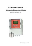
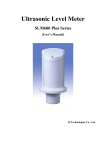
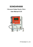
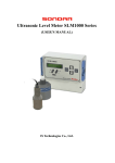
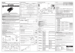
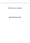
SONDAR 2000
Dual Channel Ultrasonic Level Meter
(USER’S MANUAL)
IS Technologies Co., Ltd.
SONDAR 2000
May 2001 Edition
COPYRIGHT
© IS Technologies Co., Ltd. All rights reserved. No part of this publication may be reproduced, transmitted, transcribed,
stored in a retrieval system, or translated into any language in any form without the written permission of IS Technologies
Co., Ltd.
WARRANTY AND LIABILITY
IS Technologies Co., Ltd. guarantees for a period of 1 year from the date of delivery that it will either exchange or repair any
part of this product returned to IS Technologies Co., Ltd. if it is found to be defective in material or workmanship, subject to
the defect not being due to unfair wear and tear, misuse, modification or alteration, accident, misapplication or negligence.
DISCLAIMER
IS Technologies neither gives nor implies any process guarantee for this product, and shall have no liability in respect of any
loss, injury or damage whatsoever arising out of the application or use of any product or circuit described herein.
Every effort has been made to ensure accuracy of this documentation, but IS Technologies cannot be held liable for any errors.
TECHNICAL ENQUIRIES
Please contact IS Technologies Co., Ltd. for technical support.
IS Technologies Co., Ltd.
203/504 Buchon Techno Park, 192, Yakdae Dong, Wonmi Gu, Buchon City Kyungki, Korea
Tel: 82-32-621 2606
Fax: 82-32-621 2612
Web Site: http://www.sondar.com
e-mail: [email protected]
2
Contents
Chapter 1 Introduction… ........................................................................................................................................................................ 4
About Sondar 2000 …...............................................................................................................................................................................4
Specification…...........................................................................................................................................................................................5
Chapter 2 Installation .............................................................................................................................................................................. 6
Power Supply Requirements .....................................................................................................................................................................6
Dimension… ..............................................................................................................................................................................................6
Cable Entry.................................................................................................................................................................................................7
Example…..................................................................................................................................................................................................9
Sensor Installation…............................................................................................................................................................................... 10
Chapter 3 How To Use Sondar2000 ................................................................................................................................................... 10
Operating the Controller ......................................................................................................................................................................... 10
Chapter 4 Menu Guide.......................................................................................................................................................................... 14
Application Menu Options ..................................................................................................................................................................... 14
Process Menu Options ............................................................................................................................................................................ 16
Compensation Menu Options................................................................................................................................................................. 20
Menu Option Record............................................................................................................................................................................ 23
3
Chapter 1 Introduction
About SONDAR 2000
The Sondar 2000 is a highly developed ultrasonic level measurement system which provides noncontacting level measurement for a wide variety of applications in liquids.
The Sondar 2000 operates on the principle of timing the echo received from a measured pulse of sound
transmitted in air and utilize state of the art echo extraction technology.
The relays and mA outputs may be used as preset(or programmed as desired) to activate alarms and/or
operate remote monitoring equipment and/or process control equipment.
The Sondar 2000 has an IP65 lid covering an integral LCD display and 5 buttons used for programming
purposes.
The Sondar 2000 also has two independent current outputs and choose one display option among Level1,
Level 2, Level 1 – Level 2, Level 2 – Level 1, (Level 1 + Level 2)/2 as user’s need.
The Sondar 2000 is composed of a controller and two sensors.
4
Product Specification
Physical
Dimensions
controller
Sensor
mounting
weight
sensor material
240 (width). x 185 (height) mm
67 (dia) x 160 (height) mm
3/4” NPT
Nominal 3.0 kg
PP
Environmental
IP Rating (electronics housing)
Max. & Min. temperature (electronics)
Pressure
IP65(Controller)
-20 ºC to +50 ºC(Controller), -20 to +70°C(Sensor)
up to 2 Bar
Performance
Accuracy
Less than 0.3% at the full range or 2mm
Resolution
1mm
Max. range
Liquids 8m( logical range : 10m)
Min. range
0.35 meters
Beam Angle
10o at -3dB.
Damping Rate
Adjustable from 0.1m/min to 10m/min
Temperature Compensation
Fully compensated via integral temperature sensor over entire operational span
Outputs
Analogue output 4-20mA into Max 600Ω (user adjustable) Fault condition Alarm 3.8mA / Hold / 21mA user selectable.
Display 2 Line 40 Characters LCD
Programming
On-board programming
via 5 tactile push button keys
Supply
Power supply
AC 90 ~ 260V, Less than 15VA, DC24V( Option )
5
Chapter 2 Installation
Sondar 2000 is composed of a controller unit and two sensors
Power Supply Requirements
The Sondar2000 operates from a AC supply of 90 –260V, DC 20V(Option)
All electronic products are susceptible to electrostatic shock, so follow proper grounding
procedures during installation.
The construction of the sensors can be mounted easily using the thread (3/4” NPT ).
When choosing a location to mount the sensor, bear in mind the following:
• For easy access to the LCD display and programming buttons mount it where it is easily accessible.
• The ultrasonic signal path should be free of falling material and obstructions such as pipes, beams etc.
• The sensor should be mounted at least 35cm above the maximum level of the material and be
perpendicular to the surface.
• The mounting surface should be vibration-free.
• The ambient temperature of the R2000 is between -30ºC and 70ºC.
• There should be no high voltage cables or electrical inverters close by.
• Do not use any metal substances when installing
(Please use the PVC nut & flange supplied as option)
Dimensions
Sensor
3/4" NPT
160
144
63.5
75.5
67.0
6
Controller
240
15
Sondar 2000
MODE
SET
RUN
185
145
Dual Channel Ultrasonic Level Meter
198
213
(185)
240
60
125
47
(107)
60
198
145
213
15
Cable Entry
26 terminals are aligned inside the terminal box.
Input & Output Terminal
IRTN2
IOUT2
IRTN1
IOUT1
GND
RXD
TXD
RTH2
SEN2-
SEN2+
RTH1
SEN1-
SEN1+
AGND
+12V
A1_COM
A1_NO
A2_COM
FA_COM
L
N
A1_NC A2_NO A2_NC FA_NO FA_NC
7
Function
Terminal
Function
+12V
AGND
SEN1+
SEN1RTH1
SEN2+
SEN2RTH2
TXD
+12V supplied to sensor
Connect to GND of sensor
Connect to positive wire(red) of ultrasonic sensor
Connect to shield wire(blue) of ultrasonic sensor
It’s used at factory
Connect to positive wire(red) of ultrasonic sensor
Connect to shield wire(blue) of ultrasonic sensor
It’s used at factory
RS232C interface in use, connect to transmission part
RS485 interface in use, connect to Y
RS232C interface in use, connect to reception part
RS485 interface in use, connect to Z
GND of digital communication
Current output No.1
Return the current from IOUT1
Current output No. 2
Return the current from IOUT2
Alarm1 relay NO contact point, OFF with A1_COM together when relay
operates.
Alarm1 relay COM contact point, OFF with A1_NO together when relay
operates. OFF with A1_NC together when relay doesn’t operate
Alarm1 relay NC contact point, OFF with A1_COM together when relay
doesn’t operate.
Alarm2 relay NO contact point, OFF with A2_COM together when relay
operates.
Alarm2 relay COM contact point, OFF with A2_NO together when relay
operates. OFF with A2_NC together when relay doesn’t operate
Alarm2 relay NC contact point, OFF with A2_COM together when relay
operates.
Fail relay NO contact point, OFF with FA_COM together when relay
operates.
Fail relay FA-COM contact point, OFF with FA_NO together when relay
operates. OFF with FA_NC when relay doesn’t operate.
Fail relay NC contact point, OFF with FA_COM together when relay doesn’t
operate
Connect to the line of AC power
Connect to the neutral of AC power
RXD
GND
IOUT1
IRTN1
IOUT2
IRTN2
A1_NO
A1_COM
A1_NC
A2_NO
A2_COM
A2_NC
FA_NO
FA_COM
FA_NC
L
N
Note
OPTION
OPTION
250Ω
250Ω
8
Example 1 – Level Measurement
SENSOR 1
River Side
SENSOR 2
Plant Side
Example 2 – Point Measurement
9
Sensor Installation
Above 40cm
Max. Range
15°
Less than 8cm
- Recommended Installation -
Sensor should be installed more than 40cm higher than maximum liquid level.
There is no obstacle in the ultrasonic beam angle (15°C)
Sensor should be perpendicular to the liquid level
To protect the possible error caused by diffused echo reflection, install the sensor in the middle of
waterway
After completing installation, please turn the power off and on again to check if the other program
settings are recorded.
10
Chapter 3 How To Use SONDAR 2000
Operating the Controller
Sondar 2000
MODE
S ET
RUN
D ual C h an nel U ltraso nic Level M eter
Display Window
S2000 is designed to display various data at the same time by adopting 40 Characters LCD.
The display below shows an example of a normal operation of Sondar 2000.
L1 : 8. 01m
DL : 1.00m
L2 : 9 . 01m
DT1
A1
A2
1)
L1 : 10.01 m → shows the current liquid level of channel 1
2)
L2 : 9.00m → shows the current liquid level of channel 2
3)
DL : 1.01 m
4)
DT1 → “D” : Detection. It’s flickering when returing echoes are well detected
→ shows the difference in levels between L1 and L2.
“T” : Transmittion. It also flicker with “D” in normal situation. “D” is flicking alone, it means
the target is suddenly changed or there are obstacle in the beam angle
“1” : “D”and “T” are the situation of channel 1
5)
A1
→ shows relay 1 is in operation.
11
6)
A2
→ shows relay 2 is in operation.
Button Functions
UP
MODE
SET
RUN
DOWN
* MODE Button
- Use this button only once to get into menu mode
* SET Button
- This button is used for 2 main purposes.
1) To set the value after choosing Menu option by pressing UP or DOWN button.
2) To save the value
* UP and DOWN Button
- These buttons are used to choose menu and set data
* RUN Button
- Use this button only once to return to operation mode
Checking up on operation status
- The below window is seen by pressing UP button at Run Mode.
SIG means the power of reflected echo. THR means threshold voltage.
Normally the value of SIG should be bigger than the one of THR
SIG1:
SIG2:
T H R 1:
THR2:
- The below window is seen by pressing DOWN button in operation.
D1 means Distance(from the sensor to liquid level) of channel 1 and T1 is Temperature of channel 1
D 1:
.
T1 :
m
℃
D 2:
.
T2:
℃
m
12
Current Output
-
The Sondar 2000 has two respective current outputs to level change. User can choose two current outputs
among below options.
CH1 LEVEL
CH2 LEVEL
CH1 LEVEL – CH2 LEVEL
CH2 LEVEL – CH1 LEVEL
( CH1 LEVEL + CH2 LEVEL ) / 2
Alarm Relay
-
The Sondar 2000 has two alarm relays
The relays are normally used for pump control, draining control, high and low liquid level warning, etc. at
user’s need
13
Chapter 4 Menu Guide
Application Menu Option
Password
Factory Set= 0
PASSWORD CHECK
This option is displayed by pressing MODE button. The factory set is “0”.
After inputting “0”, move to next menu by pressing SET button
Password Change
01
PASSWORD CHANGE
At this option, you can change the password by pressing SET button.
If you don’t need it, you can move to next menu by pressing UP or DOWN button.
Channel 1 Empty Distance
FactorySet=5.000m
02
CH1 EMPTY
This option sets the maximum distance from the face of the channel 1 sensor to the empty point, in meters.
Press the SET button to set the value and use UP or DOWN button to input value
Below are the window when setting the value
02
CH1 EMPTY
EMP1 :
.
m
14
Channel 2 Empty
FactorySet=5.000m
03
CH2 EMPTY
This option sets the maximum distance from the face of the channel 2 sensor to the empty point
Channel 1 Blanking Distance
FactorySet=0.350m
04
CH1 BLANKING
This option is the distance from the face of the transducer that is not capable of being measured, and is pre-set to
35cm. It should not be set to less than this figure, but can be increased if required.
Channel 2 Blanking Distance
FactorySet=0.350m
05
CH2 BLANKING
This option sets blanking distance of channel 2
15
Process Menu Options
Channel 1 Current Output
FactorySet= 1
06
CH1 OUT CURRENT
This option is to choose mA output for channel 1.
1.
2.
3.
4.
5.
CH1 LEVEL
CH2 LEVEL
CH1 LEVEL - CH2 LEVEL
CH2 LEVEL - CH1 LEVEL
(CH1 LEVEL + CH2 LEVEL) / 2
Channel 2 Current Output
FactorySet= 2
07
CH2 OUT CURRENT
This option is to chooses mA output for channel 2
Channel 1 4mA Setpoint
Factory Set = 0
08
CH1 4mA SETPOINT
This option sets the level at which the 4mA output will occur. By default 4mA will represent Empty(0% of Span).
Channel 1 20mA Setpoint
FactorySet=5.000m
09
CH1 20mA SETPOINT
This option sets the level at which the 20mA output will occur. By default 20mA will represent Full (100% of
Span)
16
Channel 2 4mA Setpoint
FactorySet = 0
10
CH2 4mA SETPOINT
This option sets 4mA setpoint of channel 2
Channel 2 20mA Setpoint
FactorySet = 5.000m
11
CH2 20mA SETPOINT
This option sets 20mA setpoint of channel 2
Alarm Operation
FactorySet = 1
12
ALARM OPERATION
This option chooses the object of alarm relay
1.
2.
3.
4.
CH1 LEVEL
CH2 LEVEL
CH1 LEVEL - CH2 LEVEL
CH2 LEVEL - CH1 LEVEL
Alarm 1 ON Point
FactorySet = 1.000m
13
ALARM1 ON POINT
This option determines the “ON” point for A1 relay.
17
Alarm 1 OFF Point
FactorySet = 1.100m
14
ALARM1 OFF POINT
This option determines the limit “OFF” point for A1 relay.
Alarm 2 On Point
FactorySet = 8.000m
15
ALARM2 ON POINT
This option determines the limit “ON” point for A2 relay
Alarm 2 Off Point
FactorySet = 7.900m
16
ALARM2 OFF POINT
This option determines the “ OFF” point for A2 relay.
Channel 1 Damping Rate
FactorySet = 2
17
CH1
DAMPING RATE
This option determines the maximum rate at which the unit will respond to an increase/decrease in level.
1 = 0.1m/min
2 = 0.5/min
3 = 1m/min
4 = 10m/min
18
Channel 2 Damping Rate
FactorySet = 2
18
CH2
DAMPING RATE
This option sets the damping rate of channel 2
Channel 1 Ouput Power
FactorySet = 3
19
CH1
OUTPUT POWER
This option is used to set the power output from the sensor to suit varying applications. By reducing the power
emitted the beam angle will be effectively reduced and can be applied as detailed below;
- Setting Range : 1 = Minimum Power
( For use on short range applications)
2 = Low Power
( For use on applications where obstructions such as pipes, beams etc. are present)
3 = Normal Power
( For use in normal condition)
4 or 5 = High Power
( For use in arduous applications where conditions are dusty, steamy or turbulent)
Channel 2 Ouput Power
FactorySet = 3
20
CH2
OUTPUT POWER
This option sets output power of channel 2
19
Compensation Menu Options
Detect Level
FactorySet = 4
CH1 DETECT LEVEL
This option determines detectable size of return echo. This is useful when the first return echo is needed in
condition where small objects creating various kinds of return echoes exist. In case the set value is big, it can be
stronger to the noise, but may not be able to detect small echo.
Detect Level
FactorySet = 4
CH2 DETECT LEVEL
This option sets the detect level of channel 2
Fail Safe Current
FactorySet = 4
FAIL SAFE CURRENT
If the Sondar 2000 fails to receive a valid echo return from the target, then the mA output can be used to indicate a
fault condition (Lost of Echo). 3.8mA, 21mA or HOLD is selectable at user’s need.
Fail Safe Time
FactorySet = 120
FAIL SAFE TIME
In the event of a fail-safe condition occurring (Lost of Echo) the fail safe timer determines the time before the mA
output indicates a fault condition (Lost of Echo)
20
Sound Velocity
FactorySet = 331.6
SOUND VELOCITY SET
This option allows for the velocity of sound to be changed according to the atmosphere the sensor is operating in.
By default the velocity is set for sound travelling in air at a temperature of 0oC.
The table below gives details of the velocity of sound in various gaseous atmospheres In all cases the velocity
indicated is that in a 100% gaseous atmosphere at 0oC. In atmospheres less than 100% it may be necessary to
check the level indicated at near empty and near full and compare with the actual level, several times, then adjust
the Sound Velocity accordingly to obtain an accurately displayed reading.
Gas
Chlorine
Carbon Dioxide.
Argon
Oxygen
Air
Ammonia
Methane
Helium
Neon
Sound Velocity
206 m/sec
259 m/sec
308 m/sec
316 m/sec
331.6 m/sec
415 m/sec
430 m/sec
435 m/sec
965 m/sec
Velocity Temperature Factor
FactorySet = 0.60
TEMP FACTOR
The sound velocity in air increases or decreases at fixed rate(0.6m/ ℃), however in atmospheres other than air it
will change at a different rate.
This option allows the rate of change in m/°C to be set according to the present atmosphere and temperature. The
level indicated, should be compared with the actual level, several times, then Velocity Temperature factor adjusted
accordingly, to obtain an accurately displayed reading.
Sensor Select
FactorySet
=Sensor1&2 On
SENSOR SELECT
21
This option chooses the operation sensor channel. In case only one sensor is in use, you can simply choose
the sensor you want to operate.
12mA Output
12mA OUTPUT
Sondar 2000 outputs 12mA regardless of measurement at this mode.
This option is useful when testing with other equipment.
22
Menu Option Record
APPLICATION
Option Details
No.
Entered Value
Description
Factory Set
Value Range
PASSWORD CHECK
0
-
01
PASSWORD CHANGE
0
0 ~ 1000
02
CH1 EMPTY
5.000m
0 ~ 9.999m
03
CH2 EMPTY
5.000m
0 ~ 9.999m
04
CH1 BLANKING
0.350m
0 ~ 9.999m
05
CH2 BLANKING
0.350m
0 ~ 9.999
1
2
3
4
PROCESS
06
CH1 OUT CURRENT
1
1,2,3,4,5
07
CH2 OUT CURRENT
2
1,2,3,4,5,
08
CH1 4mA SETPOINT
0m
0 ~ 9.999m
09
CH1 20mA SETPOINT
5.000m
0 ~ 9.999m
10
CH2 4mA SETPOINT
0m
0 ~ 9.999m
11
CH2 20mA SETPOINT
5.000m
0 ~ 9.999m
12
ALARM OPERATION
1
0 ~ 9.999m
13
ALARM1 ON POINT
1.000m
0 ~ 9.999m
14
ALARM1 OFF POINT
1.100m
0 ~ 9.999m
15
ALARM2 ON POINT
8.000m
0 ~ 9.999m
16
ALARM2 OFF POINT
7.900m
0 ~ 9.999m
17
CH1 DAMPING RATE
2
1,2,3,4
18
CH2 DAMPING RATE
2
1,2,3,4
19
CH1 OUTPUT POWER
3
1,2,3,4,5
20
CH2 OUTPUT POWER
3
1,2,3,4,5
CH1 DETECT LEVEL
4
3~15
22
CH2 DETECT LEVEL
4
3 ~15
23
FAIL SAFE CURRENT
4
3.8mA/Hold/21mA
24
FAIL SAFE TIME
120
20~999
25
SOUND VELOCITY SET
331.6
200.0~500.0
26
TEMP FACTOR
0.60
-2.0 ~ 2.0
27
SENSOR SELECT
SENSOR
COMPENSATION
21
1&2 ON
28
12mA OUTPUT
23