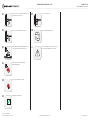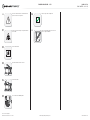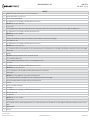
1
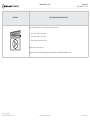
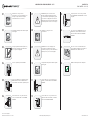
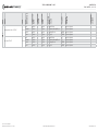
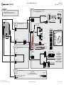
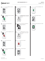
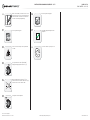
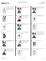
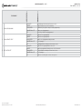
install guide
OEM-IDS(RS)-BM1-[ADS-BM1]-EN
Document number
17537
Revision Date
20141105
fiRmware
OEM-IDS(RS)-BM1-[ADS-BM1]
hardware
ADS-BM1
accessories
ADS-USB (REQUIRED)


NOTICE The manufacturer will accept no responsability for any electrical
damage resulting from improper installation of this product, be that either
damage to the vehicle itself or to the installed device. This device must be installed by a certified technician. Please review the Installation Guide carefully
before beginning any work.
U.S. Patent No. 8,856,780
Automotive Data Solutions Inc. © 2014
BEFORE INSTALLATION
1- Connect module to computer
2- Login to Weblink account
3- Flash firmware to module (module is not preloaded with firmware)
4- Use accessories accordingly (accessories are sold separately)
www.idatastart.com
Page 2 of 18
DOC.: #17537 • 20141105
VEHICLE LIST - 1 OF 1
FEATURES
REMOTE START FROM OEM REMOTES
SECURE TAKEOVER**
DATA IMMOBILIZER BYPASS
ARM OEM ALARM
DISARM OEM ALARM
DOOR LOCK
DOOR UNLOCK
PRIORITY UNLOCK
TRUNK/HATCH RELEASE
PARKING LIGHT CTRL
RAP SHUTDOWN CTRL
TACHOMETER STATUS MONITORING
BRAKE PEDAL STATUS MONITORING
VSS STATUS MONITORING
DOOR STATUS MONITORING
TRUNK STATUS MONITORING
HOOD STATUS MONITORING*
08-13 1
•
•
•
•
•
•
•
•
•
•
•
•
•
•
•
•
•
3 Series PTS AT***
06-11 1
•
•
•
•
•
•
•
•
•
•
•
•
•
•
•
•
•
3 Series Coupe PTS AT***
07-13 1
•
•
•
•
•
•
•
•
•
•
•
•
•
•
•
•
•
5 Series PTS AT
05-10 1
•
•
•
•
•
•
•
•
•
•
•
•
•
•
•
•
•
6 Series PTS AT
05-10 1
•
•
•
•
•
•
•
•
•
•
•
•
•
•
•
•
•
1M PTS AT
11
1
•
•
•
•
•
•
•
•
•
•
•
•
•
•
•
•
•
M3 PTS AT***
08-12 1
•
•
•
•
•
•
•
•
•
•
•
•
•
•
•
•
•
M3 Coupe PTS AT***
08-13 1
•
•
•
•
•
•
•
•
•
•
•
•
•
•
•
•
•
M5 PTS AT
06-10 1
•
•
•
•
•
•
•
•
•
•
•
•
•
•
•
•
•
M6 PTS AT
06-10 1
•
•
•
•
•
•
•
•
•
•
•
•
•
•
•
•
•
X1 PTS AT***
12-14 1
•
•
•
•
•
•
•
•
•
•
•
•
•
•
•
•
•
X5 PTS AT
07-13 1
•
•
•
•
•
•
•
•
•
•
•
•
•
•
•
•
•
X5 Diesel PTS AT
07-13 1
•
•
•
•
•
•
•
•
•
•
•
•
•
•
•
•
•
X5 M PTS AT
10-13 1
•
•
•
•
•
•
•
•
•
•
•
•
•
•
•
•
•
X6 PTS AT
08-14 1
•
•
•
•
•
•
•
•
•
•
•
•
•
•
•
•
•
X6 M PTS AT
10-14 1
•
•
•
•
•
•
•
•
•
•
•
•
•
•
•
•
•
Z4 PTS AT***
09-14 1
•
•
•
•
•
•
•
•
•
•
•
•
•
•
•
•
•
Clubman PTS AT***
08-14 1
•
•
•
•
•
•
•
•
•
•
•
•
•
•
•
•
•
Cooper PTS AT***
07-14 1
•
•
•
•
•
•
•
•
•
•
•
•
•
•
•
•
•
Cooper Convertible PTS AT***
08-14 1
•
•
•
•
•
•
•
•
•
•
•
•
•
•
•
•
•
Countryman / ALL-4 PTS AT
11-14 2
•
•
•
•
•
•
•
•
•
•
•
•
•
•
•
•
•
Coupe PTS AT***
12-14 1
•
•
•
•
•
•
•
•
•
•
•
•
•
•
•
•
•
Paceman PTS AT
13-14 2
•
•
•
•
•
•
•
•
•
•
•
•
•
•
•
•
•
Roadster PTS AT***
12-14 1
* If equipped with a factory hood switch.
** If equipped with an electric E-brake and it is activated, vehicle will shudown when a door is opened during RS sequence.
*** If equipped with the Confort Access System, the door handles will not be functional during RS sequence.
•
•
•
•
•
•
•
•
•
•
•
•
•
•
•
•
•
OEM-IDS(RS)-BM1-[ADS-BM1]-EN
INSTALL TYPE
MAKE
BMW
MINI
U.S. Patent No. 8,856,780
Automotive Data Solutions Inc. © 2014
GLOW PLUG STATUS MONITORING
YEAR
1 Series PTS AT
POWER LIFTGATE
MODEL
NOTES
I This firmware covers Automatic Transmission
(AT) vehicles only.
•
www.idatastart.com
Page 3 of 18
DOC.: #17537 • 20141105
BOX CONTENTS - 1 OF 1
BOX CONTENTS
MODULE
LED 1
LED 2
PROGRAMMING
BUTTON
USB
BLACK
BLACK
BLACK
BLUE
2
4
6
1
3
5
1
2
3
2
4
6
8
10
12
14
16
18
20
1
3
5
7
9
11
13
15
17
19
2
4
6
1
3
5
1
2
3
BLACK
EXPANSION PACK
BLACK
RED
2
1
BLUE
4
3
2
1
BLACK
4
3
2
1
BLUE
TELEMATIC
PORT
9 10
7 8
5 6
3 4
1 2
XP LED 1
1 2 3 4
11
9
7
5
3
1
12
10
8
6
4
2
10 PIN WHITE CONNECTOR
T-HARNESS 1
4
3
2
1
12 PIN BLACK CONNECTOR
AFTERMARKET HOOD SWITCH AND CABLE
WHITE
EXPANSION CABLE
T-HARNESS 2
BLACK
BLACK
RF PORT/WEBLINK PORT
18 PIN WHITE CONNECTOR - ADAPTER CABLE
XP LED 2
THE ADS-HRNBMW01-2 CABLE IS INCLUDED IN KITS
MANUFACTURED AFTER 11/12/2013. CONTACT YOUR
AUTHORIZED DEALER, IF THIS CABLE IS NOT INCLUDED.
EXPANSION PACK ASSEMBLY
1
2
3
4
ADS-HRNBMW01-2
LED
LED
STICKER 1
STICKER 2
1 3 5 7 9 1113 1517
2 4 6 8 10 12 14 16 18
WHITE
TOP VIEW
BOTTOM VIEW
TOP VIEW
WEBLINK CABLE (required accessory sold separately)
WEBLINK CABLE
MODULE
WEBLINK PORT
COMPUTER
USB PORT
4 PIN BLACK CABLE
U.S. Patent No. 8,856,780
Automotive Data Solutions Inc. © 2014
OEM-IDS(RS)-BM1-[ADS-BM1]-EN
www.idatastart.com
technicaL note - 1 OF 1
imPoRtant
Page 4 of 18
DOC.: #17537 • 20141105
instaLL viDeo gaLLeRY avaiLabLe onLine
Before installing this product, consult our Install Video Gallery and watch:
•
Vehicle Disassembly Procedure videos
•
Module Connection Procedures videos
•
Module Programming Procedures videos
Simply visit our forum and register at
http://www.12voltdata.com/forum/viewtopic.php?f=340&t=9683&sid=a61772b486e4584ad6f058b171ffa425
U.S. Patent No. 8,856,780
Automotive Data Solutions Inc. © 2014
OEM-IDS(RS)-BM1-[ADS-BM1]-EN
www.idatastart.com
Page 5 of 18
DOC.: #17537 • 20141105
MODULE INSTALLATION PROCEDURE - 1 OF 1
01
START vehicle. Verify all vehicle
functionalities. If the vehicle displays error
messages or any malfunction: stop the
installation and service the vehicle.
07
WARNING: Any vehicle harness that is
disconnected during installation, must be
re-connected before performing any system
tests. Failure to comply will result in vehicle
displaying error messages. An OEM scantool
will be required to clear the error messages.
13
If required, connect an accessory as shown
in the COMPATIBLE ACCESSORIES section of
the guide.
02
Turn ignition to OFF position. Remove keyfob
from keyport.
08
START vehicle. Verify all vehicle
functionalities.
14
If the vehicle is not equipped with a factory
hood switch, install an aftermarket hood
switch as shown in STEP 4 of the WIRING
DIAGRAM.
03
Verify all keyfob functionalities (Door Lock,
Door Unlock, Trunk Release and Comfort
Access System if equipped).
09
WARNING: If the vehicle displays error
messages or any malfunction, stop the
installation, verify every connection and if the
problem persists, call technical support.
15
Put sticker 1 on a clean and visible surface
in the engine bay and put sticker 2 under the
dashboard near the OBDII connector.
04
Insert the expansion pack into module.
10
Turn ignition to OFF position. Remove keyfob
from keyport.
16
Module installation procedure completed.
05
Connect the module to the computer with the
WEBLINK cable. Flash the module with the
latest firmware then flash the expansion pack.
11
Connect and secure every connector to the
module, as shown in STEP 2 of the WIRING
DIAGRAM.
06
Connect and secure every connector to the
vehicle, as shown in STEP 1 of the WIRING
DIAGRAM.
12
Connect and secure every connector of the
expansion cable to the module, as shown in
STEP 3 of the WIRING DIAGRAM.
U.S. Patent No. 8,856,780
Automotive Data Solutions Inc. © 2014
OEM-IDS(RS)-BM1-[ADS-BM1]-EN
www.idatastart.com
Page 6 of 18
DOC.: #17537 • 20141105
TYPE 1 - WIRING DIAGRAM - 1 OF 1
STEP 1
WARNING
1-TO CONNECT THE MODULE: FOLLOW STEPS 1 TO 4
2-TO DISCONNECT THE MODULE: FOLLOW STEPS 4 TO 1
CONNECT THE FOLLOWING TO THE VEHICLE
START THE VEHICLE WITH THE OEM KEYFOB
TO TEST THE CONNECTIONS
BRAKE SWITCH
A1
4
3
2
1
BRAKE HARNESS
MODULE
STEP 2
RELAY
CONNECT TO MODULE
COMFORT ACCESS SYSTEM MODULE
BLACK 20 PIN
C1
B1
MINI: BEHIND INSTRUMENT PANEL, DRIVER SIDE
BMW: UNDER DASH, DRIVER SIDE
B1 CONNECTOR
WHITE 18 PIN
B2 HARNESS
RELAY
WARNING: THE ADAPTER CABLE IS NOT REQUIRED
STEP 3
CONNECT TO MODULE
BLACK 4 PIN
C1 CONNECTOR
BLACK 6 PIN
C2 HARNESS
STEP 4
WARNING:
THESE CONNECTORS
HAVE TWO [2X] LOCKING
MECHANISMS.
INSERT THE CONNECTOR
IN ITS HOUSING AND
APPLY GENTLE PRESSURE
ON BOTH EXTREMITIES
TO SECURE THE
CONNECTION. (TWO AUDIBLE
CLICKS WILL BE HEARD.)
CONNECT IF REQUIRED
WHITE 10 PIN
IF NOT EQUIPPED
WITH AN OEM HOOD SWITCH,
INSTALL AN AFTERMARKET HOOD SWITCH
HOOD SWITCH
07 GRAY/WHITE - HOOD STATUS (-) INPUT
08 GRAY/BLACK (NOT USED)
U.S. Patent No. 8,856,780
Automotive Data Solutions Inc. © 2014
OEM-IDS(RS)-BM1-[ADS-BM1]-EN
www.idatastart.com
Paceman PTS AT
U.S. Patent No. 8,856,780
Automotive Data Solutions Inc. © 2014
13-14
MODULE
LOCATION
POLARITY
WIRE
COLOR
POSITION
CONNECTOR
TYPE
CONNECTOR
COLOR
CONNECTOR
NAME
WIRE
DESCRIPTION
MODEL
MAKE
YEAR
11-14
MINI
Countryman / ALL-4 PTS AT
COMPONENT
LOCATOR
Page 7 of 18
DOC.: #17537 • 20141105
TYPE 2 - WIRE CHART - 1 OF 1
12V
X14261
~
51 pin
02 Red/Yellow
(+)
Driver kick panel
~
Ground
X14261
~
51 pin
47 Brown or Brown/Black
(-)
Driver kick panel
~
CanH
X14261
~
51 pin
46 Orange/Green
(DATA)
Driver kick panel
~
CanL
X14261
~
51 pin
45 Green
(DATA)
Driver kick panel
~
12V
X14261
~
51 pin
02 Red/Yellow
(+)
Driver kick panel
~
Ground
X14261
~
51 pin
47 Brown or Brown/Black
(-)
Driver kick panel
~
CanH
X14261
~
51 pin
46 Orange/Green
(DATA)
Driver kick panel
~
CanL
X14261
~
51 pin
45 Green
(DATA)
Driver kick panel
~
OEM-IDS(RS)-BM1-[ADS-BM1]-EN
www.idatastart.com
Page 8 of 18
DOC.: #17537 • 20141105
TYPE 2 - WIRING DIAGRAM - 1 OF 1
STEP 1
WARNING
CONNECT THE FOLLOWING TO THE VEHICLE
START THE VEHICLE WITH THE OEM KEYFOB
TO TEST THE CONNECTIONS
1-TO CONNECT THE MODULE: FOLLOW STEPS 1 TO 4
2-TO DISCONNECT THE MODULE: FOLLOW STEPS 4 TO 1
BRAKE SWITCH
A1
4
3
2
1
RELAY
BRAKE HARNESS
MODULE
STEP 2
CONNECT TO MODULE
CUT AND REMOVE CONNECTORS
FROM T-HARNESS
BLACK 20 PIN
X14261
WHITE 18 PIN
5 AMPS
STEP 3
RED
BLACK
PINK (NOT USED)
PINK/RED
PINK/YELLOW
BLACK
CONNECT TO MODULE
12V (+) - 02
GROUND - 47
CANH - 46
CANL - 45
GROUND - 47
CONNECT
IF WIRE
IS PRESENT
BLACK 4 PIN
1
34
2
35
36
37
38
3
4
5
6
39
40
41
42
43
44
45
46
47
48
49
50
51
WHITE 18 PIN
ADAPTER CABLE
33
27
28
29
30
31
32
20
21
22
23
24
25
26
DRIVER KICK PANEL
7
8
9
10
11
12
13
14
15
16
17
18
19
X14261
KEYPORT CONNECTOR
1
RELAY
8
2
3
4
5
6
7
9 10 11 12 13 14
BLACK 6 PIN
KEYPORT HARNESS
STEP 4
WARNING:
THESE CONNECTORS
HAVE TWO [2X] LOCKING
MECHANISMS.
INSERT THE CONNECTOR
IN ITS HOUSING AND
APPLY GENTLE PRESSURE
ON BOTH EXTREMITIES
TO SECURE THE
CONNECTION. (TWO AUDIBLE
CLICKS WILL BE HEARD.)
CONNECT IF REQUIRED
WHITE 10 PIN
IF NOT EQUIPPED
WITH AN OEM HOOD SWITCH,
INSTALL AN AFTERMARKET HOOD SWITCH
HOOD SWITCH
07 GRAY/WHITE - HOOD STATUS (-) INPUT
08 GRAY/BLACK (NOT USED)
U.S. Patent No. 8,856,780
Automotive Data Solutions Inc. © 2014
OEM-IDS(RS)-BM1-[ADS-BM1]-EN
www.idatastart.com
Page 9 of 18
DOC.: #17537 • 20141105
MODULE PROGRAMMING PROCEDURE - 1 OF 1
01
LED 1 is solid RED. Insert keyfob 1 into
keyport.
07
Remove keyfob 1 from keyport.
13
LED 1 will turn solid GREEN for 2 seconds.
02
Within 10 seconds, LED 1 will flash GREEN
once (1x).
08
WARNING: Follow steps 4, 3, 2 as shown in the
wiring diagram to disconnect the module from
the vehicle.
14
Remove keyfob 1 from keyport.
03
Remove keyfob 1 from keyport.
09
Connect module to computer and proceed
with KLON programming.
15
Module Programming Procedure completed.
04
LED 1 will turn solid RED. Wait 5 seconds.
10
WARNING: Follow steps 2, 3, 4 as shown in
the wiring diagram to connect the module to
the vehicle.
05
Insert keyfob 1 into keyport.
11
LED 1 will turn solid RED.
06
Within 10 seconds, LED 1 will flash GREEN
rapidly.
12
Insert keyfob 1 into keyport.
U.S. Patent No. 8,856,780
Automotive Data Solutions Inc. © 2014
OEM-IDS(RS)-BM1-[ADS-BM1]-EN
www.idatastart.com
VALET MODE PROGRAMMING PROCEDURE - 1 OF 1
>>
NOTE: In Valet Mode, the Remote starter is not
functional. Keyless entry, Lock and Unlock will
remain functional. See RF kit user manual for
alternate valet mode programming.
06
Remove keyfob from keyport.
01
Insert keyfob into keyport.
07
Valet Mode Programming Procedure
completed.
02
Time restriction. Complete next step within 5
seconds.
>>
To exit valet mode: repeat steps 1 to 6.
03
STOP ACC
ON START
Page 10 of 18
DOC.: #17537 • 20141105
Cycle ignition ON five times [5x OFF/ON]
rapidly. Parking Light will flash once [1x].
ENGINE
START
STOP
04
05
Wait, Parking Light will flash once [1x] to
indicate that the valet mode is ON or twice [2x]
to indicate that the valet mode is OFF.
Turn ignition to STOP position.
STOP ACC
ON START
ENGINE
START
STOP
U.S. Patent No. 8,856,780
Automotive Data Solutions Inc. © 2014
OEM-IDS(RS)-BM1-[ADS-BM1]-EN
www.idatastart.com
Page 11 of 18
DOC.: #17537 • 20141105
MODULE NAVIGATION PROCEDURE - 1 OF 1
>>
It is mandatory to exit the Module Navigation
at the end of this procedure. Failure to exit the
Module Navigation will drain vehicle battery.
To exit the Module Navigation at any time:
Follow STEP 13.
04
>>
Module must be programmed to the vehicle.
05
>>
Use the Module Navigation Chart on the next
page.
06
Set ignition to OFF position.
07
TO ACCESS THE MENUS: Press and hold
programming button until LED 1 turns solid
GREEN.
08
IN THE MENUS: Press the programming
button as many times as the menu number
indicates. LED 1 will flash GREEN an equal
amount of times continuously.
09
01
STOP ACC
ON START
TO ACCESS THE OPTIONS: Press and hold
programming button until LED 1 turns solid
RED.
10
IN THE OPTIONS: Press the programming
button as many times as the option number
indicates. LED 1 will flash RED an equal
amount of times continuously.
11
TO ACCESS THE SETTINGS: Press and hold
programming button until LED 1 turns solid
GREEN.
12
Configure every other setting and proceed to
step 13.
[Z]
LED 1 will flash GREEN as many times as
the current (or default) setting number,
continuously.
13
MANDATORY: EXIT MODULE NAVIGATION.
Press and hold programming button for 7
seconds. LED 1 will flash RED rapidly. Release
programming button. LED 1 will turn OFF.
[Z]
IN THE SETTINGS: Press the programming
button as many times as necessary to access
your setting. LED 1 will flash GREEN an equal
amount of times continuously.
14
Module navigation completed.
To return to the MENUS: exit the Module
Navigation and redo the Module Navigation
Procedure.
>>
Failure to exit the Module Navigation will drain
vehicle battery.
[Y]
To save and return to the OPTIONS: Press and
hold programming button until LED 1 turns
solid RED.
[Y]
LED 1 will flash RED as many times as the
current option number continuously.
ENGINE
START
STOP
02
03
[X]
U.S. Patent No. 8,856,780
Automotive Data Solutions Inc. © 2014
OEM-IDS(RS)-BM1-[ADS-BM1]-EN
www.idatastart.com
Page 12 of 18
DOC.: #17537 • 20141105
[Y] oPtions
[X] menus
moDuLe navigation chaRt:
notes
I Default settings are listed in bold.
01
oFF
02
ON
01
oFF
02
ON
01
oFF
02
ON
01
oFF
02
ON
01
enabLe
02
DISABLE*
01
45 sec
02
90 SEC
03
03 MIN
04
04 MIN
01
DISABLE
02
N/A
03
LOCK + UNLOCK + LOCK
04
LocK + LocK + LocK
01
03 MIN
02
05 MIN
03
10 MIN
04
15 MIN
05
25 MIN
06
30 MIN
07
35 MIN
08
15 min
01
02 sec
02
05 SEC
03
08 SEC
04
10 SEC
05
15 SEC
06
20 SEC
07
25 SEC
08
30 SEC
10-15 N/A
01
N/A
01
01
N/A
01
II Make sure the option is covered on the vehicle before
attempting to change the setting.
02
03
04
05
06
07
01
[Z] settings
moDuLe navigation chaRt - 1 OF 1
DISARM/UNLOCK BEFORE START
RELOCK AFTER START
RELOCK AFTER SHUTDOWN
FORCE UNLOCK ALL ON FIRST PRESS
TAKEOVER
SECURE TAKEOVER DELAY
FACTORY KEYLESS RS SEQUENCE
CONFIGURATION
08
09
02-07 Technical Support only
MODULE RUN TIME
WAIT TO START DELAY
N/A
*Vehicle will shutdown when a door is opened.
U.S. Patent No. 8,856,780
Automotive Data Solutions Inc. © 2014
OEM-IDS(RS)-BM1-[ADS-BM1]-EN
www.idatastart.com
[X] numbeR oF
PaRKing Light
FLashes
Diagnostic
Remote staRteR eRRoR coDes - 1 OF 1
I WARNING: The following applies only when the parking
lights are connected and supported by the system.
03
Foot brake is ON.
04
Hood is open.
II After a remote starter failure, the parking lights will flash
[X] number times to indicate an error code. See table.
05
Engine tach signal is lost.
06
System is in Valet Mode.
07
Vehicle is moving (VSS).
08
Glow plug timeout error.
09
RS not synchronized. Start vehicle with OEM key for 15 sec before trying a new RS sequence.
10
N/A
11
N/A
12
N/A
13
N/A
14
N/A
15
N/A
16
CAN communication failure during RS sequence.
Remote staRteR eRRoR coDes:
notes
U.S. Patent No. 8,856,780
Automotive Data Solutions Inc. © 2014
OEM-IDS(RS)-BM1-[ADS-BM1]-EN
Page 13 of 18
DOC.: #17537 • 20141105
www.idatastart.com
I
II
III
DURING PROGRAMMING
DURING REMOTE START
WITH IGNITION OFF
U.S. Patent No. 8,856,780
Automotive Data Solutions Inc. © 2014
Diagnostic
test moDuLe
LeD 1 status
moDuLe Diagnostics - 1 OF 1
Flashing RED
Missing/wrong information from firmware or vehicle.
Solid RED
Module waiting for more vehicle information.
Flashing GREEN
Additional steps required to complete module programming.
Solid GREEN then OFF
Module correctly programmed.
OFF
No activity or module already programmed.
Flashing RED
Module incorrectly programmed.
Solid RED
Module incorrectly programmed.
Flashing GREEN
Module correctly programmed and operational.
Solid GREEN then OFF
Reset in progress.
OFF
Invalid ground when running status from remote starter.
Flashing RED
Module incorrectly programmed or connected.
Solid RED
Module not programmed. Waiting for more vehicle information.
Flashing GREEN
False ground when running status from remote starter.
Solid GREEN then OFF
Reset in progress.
OFF
Module at rest and ready for a remote start sequence.
OEM-IDS(RS)-BM1-[ADS-BM1]-EN
Page 14 of 18
DOC.: #17537 • 20141105
www.idatastart.com
MODULE RESET PROCEDURE - 1 OF 1
01
Disconnect all connectors from module except
the BLACK 20-PIN connector.
07
Reconnect all connectors.
02
Disconnect the BLACK 20-PIN connector.
08
Repeat programming procedure.
03
PRESS AND HOLD programming button while
connecting the BLACK 20-PIN connector.
>>
Failure to follow procedure may result with a
DTC or a CHECK ENGINE error message.
04
Wait, LED 1 will flash RED. RELEASE
programming button.
05
LED 1 will turn RED for 2 seconds.
06
Module RESET completed.
U.S. Patent No. 8,856,780
Automotive Data Solutions Inc. © 2014
OEM-IDS(RS)-BM1-[ADS-BM1]-EN
Page 15 of 18
DOC.: #17537 • 20141105
www.idatastart.com
TAKEOVER PROCEDURE - 1 OF 1
>>
All vehicle doors must be closed and locked
prior to remote start sequence.
06
Take over procedure completed.
01
Time restriction. Complete steps 2 to 5 within
45 seconds.
>>
Failure to follow procedure will result in
vehicle engine shutdown.
02
Unlock driver door.
03
Open driver door and enter vehicle.
04
Close driver door.
05
Press and release BRAKE pedal.
U.S. Patent No. 8,856,780
Automotive Data Solutions Inc. © 2014
OEM-IDS(RS)-BM1-[ADS-BM1]-EN
Page 16 of 18
DOC.: #17537 • 20141105
www.idatastart.com
instaLLation checKList - 1 OF 2
Page 17 of 18
DOC.: #17537 • 20141105
checKList
01
WARNING: Vehicle engine will start many times. Test in a well ventillated area.
02
Open driver door window for easy vehicle access.
03
Close all vehicle doors, hood and trunk.
04
Press LOCK button three times [3x] rapidly on the OEM keyfob to remote start vehicle.
Question 1: Does the vehicle remote start?
¨
¨
YES: Go to step 5.
05
Press LOCK button three times [3x] rapidly on the OEM keyfob to shut down vehicle.
NO: The module doesn't detect OEM remote lock button from the vehicle communication network. Check all connection, repeat step 4 and call technical support if the problem persist.
Question 2: Does the vehicle shut down?
¨
¨
YES: Go to step 6.
06
Unlock and open driver door.
07
Press LOCK button three times [3x] rapidly on the OEM keyfob to remote start vehicle.
NO: Repeat step 5. If problem persists, push vehicle start button once [1x] to shut down the vehicle and call technical support.
Question 3: Does the vehicle remote start?
¨
¨
YES: The module does NOT detect the door signal from the vehicle communication network. Press LOCK button three times [3x] rapidly on the OEM keyfob to shut down vehicle and call technical support.
08
Open hood.
NO: Go to step 8.
Question 4: Is the orange warning sticker "Sticker 1" placed under the hood?
¨
¨
YES: Leave hood open and go to step 9.
09
Close all doors.
10
Press LOCK button three times [3x] rapidly on the OEM keyfob to remote start vehicle.
NO: Put the mandatory orange warning sticker "Sticker 1", leave hood open and go to step 9.
Question 5: Does the vehicle remote start?
¨
¨
YES: Press LOCK button three times [3x] rapidly on the OEM keyfob to shut down vehicle. Go to Question 6.
NO: Go to step 11.
Question 6: Is the vehicle equipped with a factory hood switch? (Inside hood latch)
¨
¨
YES: The module does NOT detect the hood signal from the vehicle communication network. Call technical support.
11
Close hood.
12
Enter vehicle. Do NOT press brake pedal.
13
Close all doors.
14
Press LOCK button three times [3x] rapidly on the OEM keyfob to remote start vehicle.
15
Wait for the vehicle to start.
16
Press brake pedal.
NO: Install the mandatory hood switch included in the kit. Repeat installation checklist.
Question 7: Does the vehicle shut down?
¨
¨
YES: Go to step 17.
17
Apply parking brake.
18
Exit vehicle.
NO: The module does NOT detect the brake pedal signal from the vehicle communication network. Press LOCK button three times [3x] rapidly on the OEM keyfob to shut down vehicle and call technical
support.
U.S. Patent No. 8,856,780
Automotive Data Solutions Inc. © 2014
OEM-IDS(RS)-BM1-[ADS-BM1]-EN
www.idatastart.com
instaLLation checKList - 2 OF 2
Page 18 of 18
DOC.: #17537 • 20141105
checKList
19
Close all doors.
20
Press LOCK button three times [3x] rapidly on the OEM keyfob to remote start vehicle.
21
Wait for the vehicle to start.
Question 8: Is the vehicle equipped with Comfort Access System ?
¨
YES: For 1, 5, 6, X5, X6: Touch exterior driver door handle to unlock door using Comfort Access System. Within 45 seconds, go to step 22.
YES: For 3, X1, Z4, Mini: Press UNLOCK button once [1x] on the OEM keyfob. Within 45 seconds, go to step 22.
¨
NO: Press UNLOCK button once [1x] on the OEM keyfob. Within 45 seconds, go to step 22.
22
Open driver door.
Question 9: Does the vehicle shut down?
¨
YES: For Z4, X5, X6: Go to step 25.
YES: For 1, 3, 5, 6, X1: The module does NOT detect the parking brake signal or the unlock signal from the vehicle communication network. Call technical support.
¨
NO: For Z4, X5, X6: The module does NOT detect the parking brake signal correctly from the vehicle communication network. Call technical support.
NO: For 1, 3, 5, 6, X1: Go to step 23.
23
Press and release brake pedal.
24
Push vehicle start button once [1x] to shut down the vehicle.
25
Installation checklist completed.
U.S. Patent No. 8,856,780
Automotive Data Solutions Inc. © 2014
OEM-IDS(RS)-BM1-[ADS-BM1]-EN
www.idatastart.com