1
®
ScanVue Customer Interactive Kiosk
User Manual
M8000-01
ScanVue® 8000
Customer Interactive Kiosk
User Manual
(U.S. Patent No. 6,213,394 B1)
IEE, INC.
7723 Kester Avenue
Van Nuys, CA 91409
14-May-2015 Rev.C
1
®
ScanVue Customer Interactive Kiosk
User Manual
M8000-01
NOTICES
This document contains proprietary information shall not be used or reproduced or its contents
disclosed in whole or in part, without the prior written consent of IEE, Inc.
IEE, Inc. reserves the right to make improvements to the software described in this documentation
at any time and without notice. The information contained herein is subject to change without
notice and should not be construed as a commitment by IEE, Inc.
The software described in this document is provided as a licensed item in conjunction with IEE, Inc.
equipment. It may not be copied or distributed for use on other than the machines it was licensed
for.
DISCLAIMER OF ALL LIABILITIES
IEE, Inc. shall have no liability or responsibility to you or any other person or entity with respect to
any liability, loss or damage caused or alleged to be caused directly or indirectly by this
documentation or the hardware or software described in it. This includes but is not limited to any
interruption of service, loss of business or anticipatory profits or consequential damages resulting
from the use or operation of such software or computer programs.
All information in this manual was deemed correct at the time of printing. Updated versions of this
manual will be published periodically and may be downloaded in Abode Acrobat (PDF) format from
IEE’s website WWW.IEEINC.COM.
Copyright © 2015 IEE, Inc.
All Rights Reserved.
14-May-2015 Rev.C
2
®
ScanVue Customer Interactive Kiosk
User Manual
M8000-01
STANDARDS CERTIFICATION
The ScanVue® product described in this manual has been fully tested and certified by an
independent testing laboratory and is compliant with the following international standards.
UL Standard 60950 (ITE) listed product.
CSA standard C22.2 No. 950 recognized product.
RF Emmissions (Conducted):
FCC CFR Title 47 part 15 Subpart B, Class A
RF Emmissions (Radiated):
CISPR 22 called out in FCC CFR Title 47 part 15 Subpart B, Class A
EN55022, 2010/AC: 2011 Class A
EN55024: 2010
EN61000-3-2: 2006 + A1: 2009 & A2: 2009
EN61000-3-3: 2008
The internal Wireless LAN PCIe Minicard is certified by the manufacturer to be compliant
with the following standards:
EN60950-1: 2006 + A11: 2009, EN 50385: 2002, EN 301 489-17
IEC 60950-1: 2001
FCC part 15B & part 15C
CAUTIONS
Caution: DO NOT DISPLAY A FIXED IMAGE FOR EXTENDED PERIODS OF TIME AS THIS MAY CAUSE LCD IMAGE
PERSISTENCE PRODUCING PIXEL DISCOLORATION.
14-May-2015 Rev.C
3
®
ScanVue Customer Interactive Kiosk
User Manual
M8000-01
TABLE OF CONTENTS
TABLE OF FIGURES ................................................................................................................ 6
Chapter 1—Introduction ............................................................................................................ 7
Overview ..................................................................................................................................... 7
®
ScanVue 8000 Kiosk Description ............................................................................................. 7
®
ScanVue Primary Functions ..................................................................................................... 7
®
ScanVue 8000 Kiosk Operation ................................................................................................ 8
®
ScanVue 8000 Kiosk Models .................................................................................................... 9
Available Options ........................................................................................................................ 9
Configuration ............................................................................................................................ 10
Installation Requirements ......................................................................................................... 11
Interfacing to the Host Network Server ..................................................................................... 12
Application Program Interface (API) ......................................................................................... 13
Specifications ............................................................................................................................ 15
Interactive Device Support........................................................................................................ 16
®
ScanVue Accessories ............................................................................................................. 16
Chapter 2—Getting Started .................................................................................................... 17
Part 1 - SDK Installation ........................................................................................................... 18
Hardware and Software Required ............................................................................................ 18
®
ScanVue Documentation Access Instructions ........................................................................ 18
SDK Files and Software Installation ......................................................................................... 18
SDK Contents ........................................................................................................................... 19
Part 2 - Local PC (Host Server) Network Setup ....................................................................... 21
Introduction ............................................................................................................................... 21
Network Setup Example Procedure (Windows 7) .................................................................... 22
Part 3 – Sample Slideshow / Product Database Test .............................................................. 30
Test Procedure ......................................................................................................................... 30
Chapter 3— ScanVue® Connections ..................................................................................... 31
Connections For (PoE Power / Communication) ...................................................................... 31
Connections For (+12V Power / Ethernet Communication) .................................................... 31
Connections For (+12V Power / Wi-Fi (802.11b/g) Communication) ....................................... 31
Instructions ............................................................................................................................... 31
®
Mounting the ScanVue 8000 Kiosk ......................................................................................... 33
Standard Wall Mount Installation .............................................................................................. 33
Chapter 4—ScanVue® Configuration ..................................................................................... 34
UnitConfig Program .................................................................................................................. 34
Modeset Program ..................................................................................................................... 36
®
ScanVue Supported Modes .................................................................................................... 37
Wireless Network Setup ........................................................................................................... 44
WEP Encryption Settings.......................................................................................................... 44
WPA and WPA2 Encryption Settings ....................................................................................... 44
Chapter 5—Interactive Devices .............................................................................................. 45
Internally Connected Devices ................................................................................................... 45
4 Pushbutton Switches (Standard) ........................................................................................... 45
Touch Screen (Optional)........................................................................................................... 45
Externally Connected Devices .................................................................................................. 46
Serial Receipt Printer (Optional) ............................................................................................... 46
14-May-2015 Rev.C
4
®
ScanVue Customer Interactive Kiosk
User Manual
M8000-01
Appendix A—Configuring ScanVue® for Input Devices ......................................................... 49
Data Bytes (Parameters) .......................................................................................................... 49
Touchscreen Data Bytes (Parameters) .................................................................................... 49
Structure of EVENT packet....................................................................................................... 49
Appendix B—Configuring with Barcodes ................................................................................ 51
Barcode Scanner Settings ........................................................................................................ 51
®
Configuring ScanVue .............................................................................................................. 51
Support Barcodes ..................................................................................................................... 53
Appendix C—ScanVue® Initialization File.............................................................................. 56
Overview ................................................................................................................................... 56
Rules for the ScanVue.ini File .................................................................................................. 56
Initialization File (scanvue.ini) Sections & Commands ............................................................. 57
Example of Initialization File ..................................................................................................... 58
Appendix D—Creating a Slideshow (.sho File) ...................................................................... 59
Introduction ............................................................................................................................... 59
Rules for the .sho File ............................................................................................................... 59
Show File (.sho) Sections & Commands .................................................................................. 60
Slideshow Example .................................................................................................................. 61
Appendix E—Text Message Support...................................................................................... 62
Font Sets and ASCII Characters .............................................................................................. 62
Formatted Text Messages ........................................................................................................ 63
Example Formatted Database Message (Character Set) ........................................................ 63
Sample Formatted Database Message .................................................................................... 63
Appendix F—ProductInfo Protocol ......................................................................................... 64
ProductInfo Protocol Requirements .......................................................................................... 64
Introduction ............................................................................................................................... 64
Protocol Types .......................................................................................................................... 64
Normal Socket Mode (Default) ................................................................................................. 64
Open Socket (Keep-Alive) Mode .............................................................................................. 65
Errors ........................................................................................................................................ 65
Status Requests ....................................................................................................................... 65
Client Mode Changes ............................................................................................................... 66
Nominal Mode Packets ............................................................................................................. 67
Client Requirements ................................................................................................................. 70
QFX Quick File Exchange Protocol .......................................................................................... 71
Appendix G— Communication Diagnostics............................................................................ 72
14-May-2015 Rev.C
5
®
ScanVue Customer Interactive Kiosk
User Manual
M8000-01
TABLE OF FIGURES
Figure 1—Configuration Info Screens 1 and 2 ..........................................................................10
Figure 2—Simplified ScanVue® System Diagram ......................................................................12
Figure 3—Connector Location—Rear of ScanVue® ..................................................................31
Figure 4—Ethernet / PoE Connector (RJ45) Pin Assignments ..................................................32
Figure 5—Power Connector (DIN8F) Pin Assignments .............................................................32
Figure 6—Unit Configuration (UnitConfig) Screen .....................................................................35
Figure 7— Example WPA / WPA 2 Encryption Settings ............................................................44
Table 1— 4 Pushbutton Switch Mode Value Setting .................................................................45
Figure 8—Wiring a Serial Printer ...............................................................................................47
Figure 9—Interface Connector Pin Assignments .......................................................................48
Table 2—Touchscreen Data Bytes (Parameters) ......................................................................49
Table 3—Barcode Configuration Labels ....................................................................................52
Table 4—Default ASCII Character Set For TFT Display ............................................................62
14-May-2015 Rev.C
6
®
ScanVue Customer Interactive Kiosk
User Manual
M8000-01
Chapter 1—Introduction
Overview
This manual provides instructions for configuration and operation of the IEE ScanVue® 8000
Customer Interactive Kiosk with slideshow feature designed for product marketing. Included is a
description of the basic functions and features of the hardware along with a description of how
to physically install the unit in its intended location, set it up to operate on your specific network,
configure your network, and interface the IEE ScanVue® 8000 Kiosk to a back office server
through its Application Programming Interface (API).
The following chapters describe how to:
Setup and install a local desktop or laptop PC with IEE Configuration programs, initialization
file (scanvue.ini), demo graphic / text files and various support utilities.
Create slideshow presentations using SVGA color graphic images and script files.
Configure ScanVue® Kiosk using IEE configuration program UnitConfig or Modeset.
ScanVue® 8000 Kiosk Description
ScanVue® 8000 Customer Interactive Kiosk is a multi–function price verifier micro kiosk
designed to scan, verify and display price information for bar coded products.
ScanVue® 8000 Kiosk can show continuous advertising of specials or promotions, display
manufacturers “paid – for” advertising or provide other customer information. In addition to
performing a service to the customer, the ScanVue® Kiosk can directly generate advertising
revenue for the store. Special displayed advertising can be sequential graphic still images for
presenting a slideshow, short video clips using graphic images or text messages to promote
special or seasonal sales events, manufacturer’s co-op advertising, check gift card balances or
provide other customer information.
ScanVue® 8000 Kiosk is a network–connected device which uses industry standard TCP/IP
protocols for communication and interfaces to a store network server through an Application
Programming Interface (API) that resides on the network server.
ScanVue® 8000 Kiosk requires GIF or PNG images in SVGA (800x600 pixel) resolution.
Images can be edited with any good commercial image editing program such as CorelDraw or
Adobe Photoshop.
The contemporary housing design merges well with almost any store décor and custom color
combinations are available if the units are ordered in sufficient quantities. The electronics
package is completely contained in a high impact ABS injection molded case.
ScanVue® Primary Functions
Item Barcode Scan: Customer scans product UPC barcode. Product price and description
information (Images or Text) are then returned by Host and displayed on the ScanVue®.
Slideshow Feature: Idle stage where up to 150 sequential SVGA (800x600) .gif or .png
images (downloaded from the Host by ScanVue®) are sequentially displayed repeatedly until
item barcode scan. Slideshow resumes after a timeout. Short video clips (up to 8 seconds)
in the form of sequential .gif or .png images are supported at fastest rate of 18 frames/sec.
14-May-2015 Rev.C
7
®
ScanVue Customer Interactive Kiosk
User Manual
M8000-01
ScanVue® 8000 Kiosk Operation
Scanvue® Initilization File Overview
A default initialization file scanvue.ini must be located in the shared POS directory on the
network server. The .ini file controls the behavior of every unit linked to that server and
references the slideshow .sho file that initiates the slideshow presentation. When started up,
ScanVue® reads the .ini file in the shared directory. If the .ini file is not found, it will not receive
instructions to initiate and run a slideshow presentation.
Changing a mode setting value using UnitConfig modifies the saved configuration. ScanVue®
retains the new settings in non–volatile memory.
Refer to Appendix C for detailed information on how to modify the scanvue.ini initialization file.
Slideshow Overview
A slideshow is a graphics–based presentation that runs as directed by a slideshow file (.sho)
modified by the user and located in C:\POS\Shows folder. This file contains script (instructions)
listing graphic image files located in C:\POS\Graphics folder and referencing how these images are
to be presented.
Slideshow files residing in the host server Shows folder and are ‘pushed’ to the displays by
commands in the slideshow .sho file and stored in the ScanVue® volatile RAM memory. The
slideshow presentation is then executed from within the ScanVue®.
Once ScanVue® units are installed and configured, any person familiar with a PC and able to
write simple macros or script files will be able to create slideshows using Microsoft WordPad™
or a similar text editor. Image files can be obtained from various sources—downloaded from a
website, scanned in from a digital scanner or transferred from a digital camera. Familiarity with
a graphics editor program would be helpful in preparing the images for slideshow presentations.
Refer to Appendix D for detailed information on how to create a slideshow.
Network Activity
ScanVue® includes servers for FTP (port 21), ProductInfo (port 1283) and clients for FTP, SMB
(Windows networking) and QFX (Quick File eXchange) file transfer protocols. FTP, SMB or QFX can
be used to access the graphics files from the Network Server for ScanVue®’s slideshow. SMB is the
default mode.
®
NOTE: When using FTP, the FTP server pushing the slideshow file to ScanVue must be set to binary mode.
The ScanVue® requires a file server for storing graphics files and a ProductInfo server (host or
back office computer) where the price/description database is maintained. These servers may
(but do not have to be) the same physical computer. The file server must have the ScanVue®
Initialization file (scanvue.ini) along with font, graphic and slideshow script file (.sho) located in
its shared POS directory (if SMB-based) or the default directory for FTP or QFX. The file server
can be a Windows or Linux system with any OS that runs TCP/IP.
ScanVue® sends the UPC number read from a bar coded item placed under the scanner to the
Host or back office server API (ProductInfo) which uses this number as a key to find the item in
the price/description database. After the item records are retrieved, the host application
prepares the response and sends it back to ScanVue® where the information is accepted and
displayed. The response can be a graphic image (.gif or .png) or text message.
14-May-2015 Rev.C
8
®
ScanVue Customer Interactive Kiosk
User Manual
M8000-01
ScanVue® 8000 Kiosk Models
ScanVue® 8000 Kiosk is available with a SVGA color graphics LCD display.
The ScanVue® Kiosk model 8000-0000 is basic model with 10/100 BaseT Ethernet
communication.
The ScanVue® Kiosk model 8000-0100 has 11Mbps (IEEE 802.11b) Wi-Fi communication
along with 10/100 BaseT Ethernet communication.
Model Number Scheme
Model #: XXXX-XXXX-XX
1st 4 Digits: Model 8000 Series XXXX-XXXX-XX
8000
LCD - 8” SVGA Display
2nd 4 Digits: ScanVue Configuration Options XXXX- 0 X 0 0-XX
Wi-Fi
Last Digit:
0 = No 1 = Yes
Special Order: XXXX-XXXX-X X (OPTIONAL)
Printer Kit
2
Custom Color X
Please call for custom color or special request requirements
ScanVue® Kiosk models are available with Power-Over-Ethernet (PoE) 10/100 BaseT
communication or Ethernet with power input for 11-29 VDC power. A 12 VDC 2.5A (30W)
Power Supply is available as an option.
Available Options
For supported device requirements, refer to Interactive Device Support section.
For power and communication requirements, refer to Specifications section.
14-May-2015 Rev.C
9
®
ScanVue Customer Interactive Kiosk
User Manual
M8000-01
Configuration
ScanVue® Kiosk Configuration Options
®
There are 2 ways to configure a ScanVue Kiosk unit:
®
1. Commands sent across the network using the UnitConfig or Modeset programs. (ScanVue
must be able to communicate with the server on the network before configuration settings can be
changed on the network).
2. Scan special purpose configuration barcodes. Refer to Appendix B for instructions.
UnitConfig the graphical, table oriented version of modeset provides the easiest way to change the
configuration of a unit on the network (as opposed to scanning barcodes or sending modeset DOS
®
commands. UnitConfig may be installed on a desktop or laptop computer for setting up ScanVue units
without a large network complicating it. You will need a network interface card (NIC) installed in your PC
®
and configured properly to communicate with ScanVue .
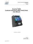
Configuration Info Screens
®
When ScanVue boots up, two configuration status screens (Fig. 1) are sequentially displayed which
show the current settings of the unit. Each screen is displayed for 10 seconds then the unit will load the
slideshow from the server and start running. These screens can be displayed at any time by scanning
‘Info Screen 1’ and ‘Info Screen 2’ bar codes shown in Appendix B under Support Barcodes.
Wireless RF configurations display brown text on a light green background and hardwired Ethernet units
display yellow text on a blue background.
®
Refer to Chapter 4 for detailed information on how to configure a ScanVue 8000 Kiosk.
Figure 1—Configuration Info Screens 1 and 2
14-May-2015 Rev.C
10
®
ScanVue Customer Interactive Kiosk
User Manual
M8000-01
Installation Requirements
Installation
The installation of ScanVue® is a reasonably easy process for a person familiar with installing
and maintaining local area networks (LAN’s). It is assumed the installation will be done by a
person having a sufficient level of technical expertise with LAN hardware and software to
understand the content of this manual and complete the job with minimal outside help. A
system or network administrator is capable of performing the installation with ease.
Setting Up a Wireless RF Link for ScanVue® Wi-Fi Models
Installation of Wireless RF communication links requires special expertise and is part of your
site network and as such the manufacturer of the wireless router or access point (and your
network staff) should be the first line of technical support. Most of the manufacturers of wireless
routers or access points have extensive technical documentation on performing RF site surveys
and correct installation of the units on their web sites.
Before installing a new wireless RF data link, it is important to perform an RF site survey to
characterize the immediate environment and ensure a reliable system is designed. The general
pointers we indicate below will assist in the initial installation and diagnosis of a link problem.
However, your first line of technical support is the specialized help available from your system
installer or IT Support. The manufacturer of the wireless router may also provide support.
1. Unobstructed line–of–sight is best. If you can, arrange the ScanVue® units so there is an
unobstructed line–of–sight to the access point. Under these ideal conditions and assuming
no interference from other 2.4Ghz sources, you should get up to 150' distance. In a typical
office or retail environment 30'–50' is more typical.
2. Mount the wireless router or access point as high as possible in the line–of–sight. This way
the signals should travel above racks, shelving, customers, etc. The human body is 90%
water and a good RF signal absorber—this is why cell phones often don’t work well inside
buildings and around crowds of other people.
3. Keep reflective surfaces like mirrors and polished stainless steel, and metal objects with
sharp points to a minimum and away from the antenna as much as possible.
4. As the ScanVue® unit cannot easily be moved once installed, it is often more convenient to
have a portable signal strength meter or an IEEE802.11b Wi-Fi module in a laptop computer
during installs. The module driver will have a RSSI graph or will display the signal strength
as a percentage depending on the module used.
14-May-2015 Rev.C
11
®
ScanVue Customer Interactive Kiosk
User Manual
M8000-01
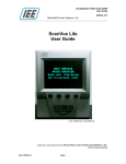
Interfacing to the Host Network Server
UPC Code
[request] sent
from scanner
Scanner
HOST
COMPUTER
MS Windows
Unix/Linux
Other
OPERATING SYSTEM
Win98/Me/2000
NT/XP Pro/ 7
Unix or Linux
Controller
Display
ScanVue®
Image and/or text
returned by HOST
Product
Images
[Graphics Files]
Product
Price &
Description
[Text File]
Relational Data Base
®
This abstract system level diagram shows the relationship between the ScanVue , the
network and the host computer supporting SMB, FTP or QFX file transfer protocol. The
API is shown at both ends for clarity. In practice the API that links the host network server
®
to the ScanVue resides on the host server.
Figure 2—Simplified ScanVue® System Diagram
14-May-2015 Rev.C
12
®
ScanVue Customer Interactive Kiosk
User Manual
M8000-01
Application Program Interface (API)
Overview
A generic bi–directional message passing protocol API called ‘ProductInfo’ has been created especially
for for retail store price–verifier applications. The ProductInfo application is required as an interface
®
between ScanVue 8000 Kiosk and the back office server that has the database containing item prices
®
and descriptions. Implementations of ProductInfo directed at specific hardware platforms, the ScanVue in
this case, are a subset of the full protocol.
®
The application that links ScanVue and the host / back office server’s database must reside on the server.
Any platform that runs TCP/IP as the network transport–protocol can be used as a server to support ProductInfo
based applications. Hardware platforms include MS Windows, Unix or Linux. Supported Operating Systems
include Windows 98, ME, 2000, NT, XP, 7, Unix, Linux and VAX. Known databases running on the OS can be
Oracle, MySQL, Microsoft SQL Server and OpenVMS.
®
The ProductInfo Server application program is responsible for receiving a request from a ScanVue after
a barcode scan, retrieving the price and description from the database and returning that data to the unit
that initiated the request. The development and maintenance of any host computer based application
program required to access a product–information database is the sole responsibility of the end user or
their system integrator. IEE provides a sample ProductInfo server API Demoserv included in the SDK.
License free Demoserv “C” source code is included to assist the end user in writing applications on their
host machine. Demoserv is written in ANSI “C” and can be integrated with any ANSI ‘C’ compiler.
Description
®
ScanVue has an embedded protocol engine that uses TCP/IP to send the UPC barcode number from
®
the ScanVue to the host computer, and return the price and description information retrieved from the
host computers’ database by its resident application.
ProductInfo is a TCP based, bi–directional message–passing protocol that uses the same format when
moving data in either direction. In normal operation, the client opens a connection for each request
generated, usually a scanned barcode, and keeps it open until the server instructs the client to close it.
The client can also wait for the server to open a socket thus allowing asynchronous operation.
The protocol also sends events marking a change of state (opening or closing) of any of the four optional
front panel switches. These events may be used by the hosts resident application to control functions or
modes within the application, for instance to change language displayed when a switch is pressed.
®
An abstract system level diagram showing the relationship between ScanVue , the network and the host
computer is shown in Figure 2. The API is shown at both ends of the network for clarity. In practice, the
®
application to interface the host computer server to ScanVue will reside on the host computer.
In the interest of robustness, both ends accept any message whether defined or not, invalid or unknown
messages are simply discarded. A maximum reasonable message length may be used as a means
to detect implementation bugs that could result in loss of synchronization. Such errors terminate
the connection. If the client detects it, it may send an error token following re–establishment of the
connection in order to log the error on the server. If the server is able to detect this condition, it can log it
®
directly. When the server receives a product query from the ScanVue , it must respond even if the
message is just to terminate the connection. Following submitting a query, the client may choose to take
an error action if it receives nothing from the server within a defined timeout period. The server can make
capability queries and/or mode changes before, during, after, or in lieu of sending any response. If the
server wishes to space messages more widely than the client’s default timeout, it must send a
‘Set Mode’ packet to change the timeout; this need only be done once per query, but must be
done on each query.
14-May-2015 Rev.C
13
®
ScanVue Customer Interactive Kiosk
User Manual
M8000-01
The client may send capability messages regardless of whether the key name is known to the server and
the server may retain this information. When the server needs to know the value of one of these
capabilities, it can consult this retained information. If it is not known, a capability query may be sent and
the server may wait a moment for a reply to be received. This reply will asynchronously update the
server’s information, and the value should be found there by a subsequent lookup following the brief
interval required for the client to respond to the query. If it remains undefined, it can be assumed that the
client declined to respond, probably because that capability name is not known to it.
Mode settings allow the server to select between optional behaviors or parameters in the client.
Theoretically, this can work both ways. If the server wants the client to adopt a certain mode setting, it
sends the command and the client will respond appropriately. If not, an error report may be generated in
response. Mode settings occupy a separate name–space from the capabilities table. A mode setting
could be used to change the timeout value the client uses to decide that a socket connection has broken.
Error reports are used primarily as a debugging tool. The string starts with an error number, optionally
followed by white–space and explanatory text. In the nominal case, messages consist of a length,
followed by a token, possibly followed by more information as specified by the length and the token. In the
trivial case, the message consists solely as a NUL–terminated text string; this is the case when each of
the four bytes of length field is an ASCII printable character. When such a message is received by the
server, it is interpreted as a product query; it optionally
contains the client’s identification and white–space preceding the product code. When received by the
client, it is interpreted as a single, textual response to a query.
The (ProductInfo Server) is described in more detail in Appendix F.
Protocol Implementation Rules
1. Mode values changed during a query session are only retained during that session.
2. The host can make “permanent” changes to mode values for query sessions by connecting to the
ProductInfo protocol port (Port 1283) of the client and setting the values. As long as that connection is
maintained, the new values will be used in all further queries.
3. Whether a “permanent change” will survive a power cycle of the client is implementation dependent.
Clients may provide special functions to record mode information in non–volatile storage.
4. Query sessions are best kept limited to information that is to be displayed immediately, so that further
queries can be answered.
5. Mode values that start or end with whitespace must be sent enclosed in double quotes. These quotes
are removed when the value is stored. Double quotes within the string are treated as part of the value.
14-May-2015 Rev.C
14
®
ScanVue Customer Interactive Kiosk
User Manual
M8000-01
Specifications
Display:
SVGA (800x600 pixel) color graphics 8” Diagonal LCD display
Network Server Computer Requirements:
MS Windows, Unix, Linux, VAX or any other platform that runs a TCP/IP network
Supported Operating Systems:
Windows 98, ME, 2000, NT, XP, 7, Unix, Linux and Open VMS
Power Options:
Wi-Fi and Ethernet Models: 11-29 VDC, 10 W typ. (24 VDC Nominal)
PoE Hardwired Models: 48 VDC, 10 W typ. (IEEE 802.3af compliant)
Communication Options:
11Mbps (IEEE 802.11b) Wi-Fi *
TCP/IP peer-to-peer Ethernet 10/100 Base-T
Power-over-Ethernet (PoE)
Supported Interactive Devices:
4 front panel push button event switches
Input Device Options:
An external RS232 serial port is available via an optional Y cable that supports a serial
receipt printer or other serial device.
2 USB ports – (For any desired future use such as MSR, please contact Sales)
1D/2D Barcode Scanner:
Supports any 1D and 2D bar codes including PDF417 codes. UPC and NCR prefix support.
ScanVue Software:
Operating System: Embedded Linux
Slideshow Presentation:
Image Format: GIF, PNG
Image Resolution: SVGA (800x600)
Maximum Number of Images: 150
Fastest Frame Rate (Video Clip Support): 18 Frames per Second
Configuration Setup:
On Line: UnitConfig, Off Line: Barcodes
Security:
WEP*
WPA - WPA-PSK, TKIP
WPA2 - WPA-PSK, CCMP
Tools:
SDK (software developers kit) includes ScanVue® configuration programs (UnitConfig and
Modeset), Sample API program (Demoserv), sample code, font files, demo graphic images,
demo text files and user manual
®
*NOTE: WEP (Wireless Equivalent Privacy) encryption continues to be supported by ScanVue , however, the
recommended solution to WEP security problems is to switch to WPA2 (Wi-Fi Protected Access).
14-May-2015 Rev.C
15
®
ScanVue Customer Interactive Kiosk
User Manual
M8000-01
Interactive Device Support
4 front panel push button switches
(Standard installed device)
(TCP/IP network communication - A bank of 4 mechanical pushbutton event switches located on the
front bezel)
-
These switches have no pre–assigned functions, but when enabled and depressed send the switch number
and time–close event to the host computer.
When a button is pressed, its switch number token will be stuffed into the EVNT packet and transmitted to
the host computer for further action by the server based application
Fujitsu model FP-1000 thermal 3” receipt printer kit
(Contact IEE Sales for this option)
(Serial RS-232 communication - Requires optional Y cable – The printer is powered separately)
-
®
Serial RS-232 Communication - ScanVue receives pre-formatted data and control codes from a printer
driver resident on the network host, which it passes, unmodified, through DIN 8 Connector (Serial RS-232)
to the printer. Default Communication is 9600 BAUD, 8-bit, no Parity and 1 stop bit. 19200 BAUD is
available setting.
Resistive touch screen
(Contact IEE Sales for this option)
ScanVue® Accessories
+12 VDC 2.5A (30W) Power Supply (IEE P/N 39055-01) with a standard 8 pin DIN male
connector to power ScanVue® (Typically not included with ScanVue®). The input is universal
90-264VAC/50-60Hz and the power supply has global certifications.
48 VDC, 10 W typ. (IEEE 802.3af compliant) Power Over Ethernet (PoE) Injector
(IEE P/N 90180-01) with dual RJ45 jacks (J2 Ethernet IN - J1 Power / Ethernet OUT to
ScanVue®) - (Typically not included with ScanVue®). The input is 100-250VAC/47-63Hz.
Printer interface cable for Fujitsu model FP-1000 or equivalent printer (IEE P/N 38578-01)
Y cable for ScanVue® with Fujitsu model FP-1000 or equivalent printer (IEE P/N 70665-01)
Y cable, RS232 Universal with DB9F connector (IEE P/N 38516-07)
6' DC power extender cable with DIN8F to DIN8M connectors (IEE P/N 37082–72)
14-May-2015 Rev.C
16
®
ScanVue Customer Interactive Kiosk
User Manual
M8000-01
Chapter 2—Getting Started
This Chapter describes how to set up and operate a factory default IEE ScanVue® 8000
Interactive Kiosk on your laptop or desktop PC (Host Server). Several programs are installed
that let you demonstrate the capabilities of the ScanVue® 8000 Kiosk and make use of the tools
and utilities provided in the SDK package downloaded from IEE’s web site. These programs can
be used as demonstration tools.
Part of the process is to change the network settings of your computer so that it can
communicate with a factory default ScanVue® 8000 Kiosk. If you need to set your computer
back to its original settings, note down all the original settings before you make the changes.
If your computer is already setup to operate on a private company network, IEE recommends
consulting with your IT group before performing this procedure.
14-May-2015 Rev.C
17
®
ScanVue Customer Interactive Kiosk
User Manual
M8000-01
Part 1 - SDK Installation
Hardware and Software Required
Laptop (or desktop) computer with Windows 98/ Me / 2000 / NT / XP Pro / 7
LAN system with TCP/IP network protocol.
Router or switch for connecting ScanVue® 8000 Kiosk to network.
Category 5 standard straight cable when using a router or switch (or a “crossover”
network patch cable when connecting directly to Host Server)
IEE ScanVue® 8000 Interactive Kiosk SDK
ScanVue® Documentation Access Instructions
Please follow link for available ScanVue® Interactive Kiosk documentation and Software
Developers Kit (SDK) from IEE web site:
http://ieeinc.com/downloads
1) To download Software Developer’s Kit for setting up a PC as ScanVue® Station Server
with utilities, click on SDK_8000.zip and save to your choice directory.
2) Extract all files from SDK_8000.zip.
3) Refer to SDK Contents section for description of folders and their contents.
SDK Files and Software Installation
Before installing the ScanVue® programs, IEE highly recommends you install the latest updates
or service packs to the operating system you are using.
1) Simply copy the entire POS folder and sub-folders into C:\ directory on your host
system. POS folder must be shared per instructions in Part 2 of this Chapter.
2) Refer to instructions described in Part 2 of this Chapter to prepare the host server for
communication with ScanVue.
3) Refer to instructions described in Part 3 of this Chapter to perform sample slideshow
and product database test.
With default scanvue.ini file installed into C:\POS folder along with sub-folders containing
sample script (.sho) and image files, ScanVue® unit can then look for scanvue.ini file located in
the shared POS share when it boots up and will not operate if it can’t find it. The .ini file will be
searched for in all lower case characters. This takes care of servers that are case sensitive
(such as Unix).
For servers that are running other than Windows, sources are provided for the server software.
There are also freely available drivers to allow any operating system to act as a Windows–type
server.
14-May-2015 Rev.C
18
®
ScanVue Customer Interactive Kiosk
User Manual
M8000-01
SDK Contents
Documentation Folder
Contains Manual and support documentation
POS Folder
fonts
Folder containing sample font files that may be downloaded to the
ScanVue® during boot up when specified in the scanvue.ini file (Ex:
FontFile = fonts/Cantarell-Bold.ttf). Only one font at a time can reside in
ScanVue®. A default FONT is used unless an alternate True Type Font
(TTF) is declared in the scanvue.ini file.
NOTES:
TTF Fonts replace GFT Font files previously used in older ScanVue models.
Shows
Folder containing sample slideshow script presentation “show” files
(TestImages_8gif.sho) and (TestImages_8png.sho) specifying the order
and duration slideshow (.gif) and (.png) images are to be displayed.
Graphics
Folder containing sample slideshow (.gif) and (.png) image folders.
Test_800
Folder within Graphics folder containing the .gif and .png images
required for the sample slideshow located in the “Shows” folder.
Images
Folder containing the images used for the sample item barcodes used
with the demo server.
ScanVue.ini
The ScanVue® initialization file that controls the behavior of every unit
linked to a server and references the slideshow .sho file that initiates the
slideshow presentation. Refer to Appendix C for file requirements.
UnitConfig
A GUI program identified by
logo used for setting up ScanVue® from
the network. Written in VisualBasic, the .exe, VB sources and an OCX
are provided. Modeset is the associated DOS program
modeset.exe
Command line utility for setting ScanVue modes instead of UnitConfig.
demoserv.exe
A sample ProductInfo query server application.
data.dat
The "database" of a few items used by sample ProductInfo query server
API Demoserv.
data.dat.documented
Documentation and sample on how the data.dat file is organized.
Application Examples Folder
Modeset Examples
Contains DOS command line batch program examples using Modeset
utility that can be used to configure a group of ScanVue units at one time.
14-May-2015 Rev.C
19
®
ScanVue Customer Interactive Kiosk
User Manual
M8000-01
Support Utilities Folder
qfxserv.exe
QFXserv.exe (Quick File Exchange Server) is a low-overhead, highspeed file server.
scanserv.ocx
ScanServ.ocx is a library you can use to create your own ProductInfo
server in Visual Basic or other Microsoft languages.
scanserv.exe
A sample server written in VB, using scanserv.ocx.
nanoserve.exe
A very simple demonstration product query server.
heartbeat.exe
Utility that periodically checks a ScanVue unit and retrieves operational
information.
probe.exe
A special version of heartbeat that gets the ScanVue's information
just once.
sst.exe
Test program for sending text to a serial printer.
UnitConfig Driver Installation (Win7) Folder
Windows 7 UnitConfig Driver Installation.pdf
Driver registration procedure required for running UnitConfig and Modeset
programs on Windows 7 (32 Bit and 64 Bit) OS.
(32 Bit OS Drivers):
richtxt32.ocx
Files required to be registered in Win7 (64Bit OS)
msflxgrd.ocx
to run the UnitConfig program.
comdlg32.ocx
Files registered are located in directory: c:\windows\system32\
(64 Bit OS Drivers):
richtxt32.ocx
Files required to be registered in Win7 (64Bit OS)
msflxgrd.ocx
to run the UnitConfig program.
comdlg32.ocx
Files registered are located in directory: c:\windows\syswow64\
Source Files Folder
Contains source code for demo servers and some utilities. The sample
programs demonstrate communications with ScanVue® using the
ProductInfo and QFX protocols and include ProductInfo and QFX
servers. The VB sources and an OCX are provided for the Unit
Configuration program so it may be embedded in the host application. All
other programs are written in ANSI C and have been compiled and run
without modification under NT, linux, UNIX, and VMS. QFX is a faster,
lower overhead alternative to FTP and SMB and provides the added
benefit of supporting graphic files in any format.
14-May-2015 Rev.C
20
®
ScanVue Customer Interactive Kiosk
User Manual
M8000-01
Part 2 - Local PC (Host Server) Network Setup
Introduction
ScanVue® 8000 Kiosk comes factory defaulted with IP address set for DHCP. This is for
automatically obtaining IP addresses assigned from a network server when performing
installations. The ScanVue® will default to 192.168.0.1 if you don’t have a DHCP server installed
on your network.
This section describes how to setup a local desktop or laptop PC (Host Server) to communicate
with a factory default ScanVue® 8000 Kiosk. A router is expected to be installed on your network
with DHCP server enabled. The Host Server must be set for Ethernet communication allowing
for further configuration using IEE’s configuration program UnitConfig or Modeset. See
Chapter 4 for ScanVue® Configuration.
This process is specific for Windows 7 OS, however, Windows OS (98/ NT, 2000, and XP) are
also supported. Your computer will be configured as a network server with one client.
If you need to set your computer back to its original settings, note down all the original settings
before you make the changes. If your computer is already setup to operate on a private
company network, IEE recommends consulting with your IT group before performing this
procedure.
(Note: If a ScanVue® is connected directly to a PC without a router or switch, a crossover cable
must be used).
ScanVue® Factory default network settings:
IP Address:
Sub-Net Mask:
WINSserverIP:
Unit ID:
14-May-2015 Rev.C
(via DHCP)
255.255.0.0
10.0.10.13
ScanVue
Username:
Windows Serv:
password:
shareName:
21
GUEST
SVSERVE
(Not Set)
POS
®
ScanVue Customer Interactive Kiosk
User Manual
M8000-01
Network Setup Example Procedure (Windows 7)
1. Preliminary
Disable your Windows 7 Firewall or Anti-Virus.
2. Set to Use Sharing Wizard
Click “Start” then “Control Panel”.
Click Tools on menu bar then click on “Folder Options”.
Click the tab labeled “View”.
Scroll to the bottom of the list to the check box labeled “Use Sharing Wizard” and
check this box. (See below)
Close “Folder Options” window.
14-May-2015 Rev.C
22
®
ScanVue Customer Interactive Kiosk
User Manual
M8000-01
3. Share POS Folder
In C: directory, right-click POS folder and select Properties, then click Sharing tab.
Click Share button to enter File Sharing window.
In File Sharing window, click on right side of entry window and select “Everyone”
from list then click [Add] button (See below).
Everyone should be shown with Read privileges.
14-May-2015 Rev.C
23
®
ScanVue Customer Interactive Kiosk
User Manual
M8000-01
Click Security tab and make sure Everyone is shared as shown below.
Click Edit button to change Permissions for POS as shown below.
Close POS Properties.
14-May-2015 Rev.C
24
®
ScanVue Customer Interactive Kiosk
User Manual
M8000-01
4. Network Security Settings
Enter Control Panel All Control Panel Items Network and Sharing Center
Under “View your active networks” section, click “Local Area Connection”.
Verify network communication is established with status similar to the following
example.
(Note: Host Server obtains IP address from router DHCP server referenced in example as
IPv4 Address 10.0.10.79)
Close Network and Sharing Center window.
14-May-2015 Rev.C
25
®
ScanVue Customer Interactive Kiosk
User Manual
M8000-01
5. Change Computer Name
Enter Control Panel All Control Panel Items System Computer Name
tab.
Double-click Change settings.
In the System Properties window, click Change button to bring up Computer name
/ Domain Changes window.
Enter SVSERVE in Computer name field.
Note: Workgroup must be selected with any description, provided it is 8 characters
or less, no spaces.
Click OK button.
Follow displayed instructions to restart computer.
14-May-2015 Rev.C
26
®
ScanVue Customer Interactive Kiosk
User Manual
M8000-01
6. Enable User Guest Account
Enter Control Panel All Control Panel Items User Accounts to display
administrator account.
Click on “Manage another account” to show Guest account.
If the Guest icon says Guest account is off, click the Guest icon to display the
following window.
14-May-2015 Rev.C
27
®
ScanVue Customer Interactive Kiosk
User Manual
M8000-01
Click Turn On button to enable Guest account.
Guest account should then be indicated as follows:
Close the Manage Accounts window.
14-May-2015 Rev.C
28
®
ScanVue Customer Interactive Kiosk
User Manual
M8000-01
7. Allow ScanVue “Guest” Account on Host Server Network
For Windows 7, Guest account is denied access on the network by default. This process removes
Guest as a denied account from network server security settings policy.
Click “Start”
In Search programs and files field, type and enter GPEDIT.MSC. The Local
Group Policy Editor will open.
Enter Computer Configuration Windows Settings Security Settings
Local Policies User Rights Assignment
Double-click on Deny Access to the Computer from the Network. (See
window below)
Guest account may be shown as indicated below:
With SVSERVE\Guest highlighted, click Remove to remove Guest then click OK.
Close Local Group Policy Editor. Network setup is completed.
14-May-2015 Rev.C
29
®
ScanVue Customer Interactive Kiosk
User Manual
M8000-01
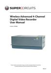
Part 3 – Sample Slideshow / Product Database Test
Test Procedure
1) Connect ScanVue® to Host Server Network as described in Chapter 3.
2) Apply power—the ScanVue® unit will start its boot–up sequence.
3) A sample slideshow (TestImages_8gif.sho) cycling through test images should be
loaded and displayed if Host Server has been set up as previously instructed.
4) Run sample ProductInfo server application (Demoserv.exe) located in POS folder and
scan following sample barcodes to test ScanVue operation using sample product
database text file (data.dat). The first 4 barcodes produce sample 320x240 size graphic
images. The Font Set barcodes produce text messages.
5) Press all four pushbutton switches and verify graphic image response for each switch.
This also uses (data.dat) database file.
TEST BARCODES
Phones (Scan 1 time)
Electronics (Scan 1 time)
Radios (Scan 3 times)
T-Shirts (Scan 1 time)
Font Set (Part 1)
Font Set (Part 2)
14-May-2015 Rev.C
30
®
ScanVue Customer Interactive Kiosk
User Manual
M8000-01
Chapter 3— ScanVue® Connections
Refer to (Figure 3) for ScanVue® rear connections.
Refer to (Figure 4) for Ethernet pin assignment.
Refer to (Figure 5) for +12Vdc power pin assignment.
Connections For (PoE Power / Communication)
PoE Hardwired connection requires only 1 cable:
CAT-5 standard straight Ethernet cable 48 Vdc (IEEE 802.3af compliant)
Connections For (+12V Power / Ethernet Communication)
Ethernet only (non-PoE) connection requires 2 cables:
+12 Vdc power to ScanVue® DIN8F connector.
CAT-5 standard straight Ethernet cable to ScanVue® Ethernet Interface connector (or a
“crossover” network patch cable when connecting directly to Host Server)
Connections For (+12V Power / Wi-Fi (802.11b/g) Communication)
Wi-Fi models require DIN8 power and hardwired Ethernet connection (required for
network settings configuration):
+12 Vdc power to ScanVue® DIN8F connector.
CAT-5 standard straight Ethernet cable to ScanVue® Ethernet Interface connector (or a
“crossover” network patch cable when connecting directly to Host Server)
Instructions
1. Connect ScanVue® per requirements indicated above.
2. Apply power—the ScanVue® unit will start its boot–up sequence.
Figure 3—Connector Location—Rear of ScanVue®
14-May-2015 Rev.C
31
®
ScanVue Customer Interactive Kiosk
User Manual
M8000-01
Ethernet / PoE Connector (RJ45) Pin Assignments
The following table identifies the locations for the Ethernet port pins and PoE power pins (if used).
Ethernet RJ45 Pin Assignment
PIN. NO.
8-Pin RJ45 Pinout
FUNCTION
1
TXD (+)
2
TXD (-)
3
RXD (+)
4
+ POWER
5
+ POWER
6
RXD (-)
7
- POWER
8
- POWER
Figure 4—Ethernet / PoE Connector (RJ45) Pin Assignments
Power Connector (DIN8F) Pin Assignments
The following table identifies the locations for the +12 Vdc Power pins.
Power DIN8F Assignment
PIN. NO.
Power DIN8F Pinout
FUNCTION
1
GND
2
POWER +12 VDC (2.5A)
3
INTERNAL CONNECTION
4
INTERNAL CONNECTION
5
INTERNAL CONNECTION
6
INTERNAL CONNECTION
7
POWER +12 VDC (2.5A)
8
GND
Figure 5—Power Connector (DIN8F) Pin Assignments
14-May-2015 Rev.C
32
®
ScanVue Customer Interactive Kiosk
User Manual
M8000-01
Mounting the ScanVue® 8000 Kiosk
Standard Wall Mount Installation
The ScanVue® 8000 Kiosk is VESA MIS-D (100 x 100 mm) standard mount supported (3.940” x
3.940”) and can be mounted on any type of flat vertical surface using the four (4) threaded PEM
P/N ITB-032 mounting holes located on the rear using # 10-32 fasteners. The closest metric
fastener would be M5 x 0.8. Mounting hardware is not provided as the material used in the
vertical wall can vary depending on the location chosen.
14-May-2015 Rev.C
33
®
ScanVue Customer Interactive Kiosk
User Manual
M8000-01
Chapter 4—ScanVue® Configuration
UnitConfig Program
Configuring ScanVue® units over the network requires a GUI program called Unit Config or
Modeset program described below. Unit Config provides a simple graphical way to query and
configure any ScanVue® unit using mode commands.
Changes can also be made off–line that will allow the unit to connect to the network using
Configuring with Barcodes method (See Appendix B) without requiring the PC. Generally,
configuration by special barcode is kept for those occasions when a devices network configuration
is incompatible with the local network. Once the unit is network compatible the rest of the
configuration can be done through UnitConfig.
Using UnitConfig
Start UnitConfig
blank.
Button / Field
program. When UnitConfig program is first started, all program fields are
Instruction
Enter the IP address of the ScanVue® unit you wish to change in the Unit IP
Address field
Restart Unit
Click the Read Modes button. All the Modes and their Content (values) will be
read from the subject unit and displayed as shown in Figure 6
To change a mode value; highlight the New Content field in the same row as
the mode you want to change by clicking on it. Enter the new value in the field
and click the Set Mode button. If the value is accepted, the field and the button
will turn green. If it is not accepted, the field and button will turn red. The light
color area at the bottom of the screen will display context sensitive help
message for each mode as the mode is highlighted. For some modes, the
values available are indicated in this area.
Now click the Commit button. This will commit the change to memory in the
ScanVue® unit. Multiple changes can be made before committing them. If any
of the changes are not accepted, the Set Mode button will turn red and those
changes marked in red were not made.
Clicking the Close button will blank all fields allowing a new IP address for
another unit to be entered
Clicking the TextReset button will apply changes made to text modes so they
can be seen immediately. As with other modes, the changes are not
permanently stored until the Commit button is clicked
The SaveToFile button will save the setup to a text file where it can be stored
and printed if necessary. This is usually done for troubleshooting or maintaining
hard copy records of each unit’s configuration
The Restart Unit button will cause a ‘soft boot’ of the selected unit
Exit
The Exit button closes the UnitConfig program
Read Modes
Set Mode
Commit
Close
TextReset
SaveToFile
14-May-2015 Rev.C
34
®
ScanVue Customer Interactive Kiosk
User Manual
M8000-01
Figure 6—Unit Configuration (UnitConfig) Screen
Configuration Notes
®
1. Set DHCP in unitIP to change to (via DHCP) for ScanVue to obtain an IP Address from a network DHCP server.
2. Most modes can be set to factory default or (Not Set) value by entering double quote [“”] or [–default–] as the
value.
3. Named Server Feature: Product info server modes SloppiIPand AlternateSloppiIP in addition to the QFX demo
server mode QFXServer may be entered as either a server IP address or as a server name. The name may be
up to 12 characters long.
14-May-2015 Rev.C
35
®
ScanVue Customer Interactive Kiosk
User Manual
M8000-01
Modeset Program
Modeset (a DOS command line program associated with UnitConfig) may be used in place UnitConfig
to query and set modes via a batch program file or directly from the DOS prompt.
Examples:
The following command sets ScanVue unit (IP address: 10.0.30.134) to values within TEST01.INI file,
then commits change to memory and restarts ScanVue:
modeset -s -fTEST01.INI -c -r 10.0.30.134
The following command sets ScanVue to specific value (Wireless=TRUE):
modeset -iWireless=True 10.0.30.134
The following command instructs ScanVue to display a text message (top line only):
modeset –l”Display a message!” 10.0.30.134
Modeset command can also be used to batch program or text message a group of ScanVue units at one
time. Refer to Modeset Example folder in the SDK.
Modeset command by itself lists all non-hidden modes and their values
ModeSet Options:
14-May-2015 Rev.C
36
®
ScanVue Customer Interactive Kiosk
User Manual
M8000-01
ScanVue® Supported Modes
Note:
1. Mode names are NOT case sensitive.
®
2. Set DHCP in unitIP to change to (via DHCP) for ScanVue to obtain an IP Address from a network DHCP
server.
3. Most modes can be set to factory default or (Not Set) value by entering double quote [“”] or [–default–] as the
value.
Fixed Unit Identification
Configuration Mode
Version
DateTime
BuildInfo
ProductName
SerialNumber
QueryViaBrowser
Description
Software version number; read–only
Not available!
The date and time of the software release in the format
YYYYMMDD; read–only.
Default “ScanVue”; read–only.
Contains the unique serial number for the unit; read–only.
IEE factory setup (Always FALSE for Non-Browser
configuration)
Default
xx.xx
YYYYMMDD
ScanVue
999999
FALSE
Note: This configuration setting is not available for ScanVue models
containing software prior to version (11.01 - “ver. 1.008”).
User Configurable Unit Identification
Configuration Mode
Description
UnitID
The host name of the unit, 19 characters maximum
UnitIP
The IP address of the unit, in standard IP dotted notation.
Unit IP default is 192.168.0.1 with no connection and with
no DHCP server available.
UnitMask
The network mask for the unit, in standard IP dotted
notation.
Unit Mask default is 255.255.0.0 with no connection and
with no DHCP server available.
GatewayIP
The IP address of the gateway machine, in standard IP
dotted notation. Required only if access to the various
hosts must be routed on the LAN
UserName
The username ScanVue uses when logging into the file
server
Password
The password ScanVue uses when logging into the file
server
ServerType
Sets the file host as Windows networking (“SMB”), FTP
(“FTP”), or QFX (“QFX”)
14-May-2015 Rev.C
37
Default
ScanVue
(via DHCP)
or…
192.168.0.1
(via DHCP)
or…
255.255.0.0
10.0.10.13
GUEST
(Not Set)
SMB
®
ScanVue Customer Interactive Kiosk
User Manual
M8000-01
Setup for Windows Networking (SMB)
Configuration Mode
Domain
DNS
NetworkName
WINSserverIP
windowsServ
ShareName
Description
Network domain is required when security is a concern
Domain Name Server IP Address (if required to resolve
network host names)
Name of the wireless network (ESSID). Identifies the
network wireless router or access point for wireless units
The IP address of the WINS server, in standard IP dotted
notation, if the file server is not on the local network
The host name of the Windows server or IP address of
the WINS server
The name of the shared directory on the Windows server
Default
(Not Set)
10.0.10.13
INSTALL
10.0.10.13
SVSERVE
POS
Setup for FTP, QFX, PRODUCTINFO (Demoserv)
Configuration Mode
FTPServerIP
QFXPort
QFXHost
QFXTimeout
SloppiHost
AlternateSloppiHost
SloppiPort
sloppiTimeout
14-May-2015 Rev.C
Description
The IP address of the FTP server in standard IP dotted
notation
The IP port to use for QFX communications
The IP address of the QFX server
The number of hundredths of a second to wait before
timing out on QFX communications
Default
10.0.10.13
The IP address of the PRODUCTINFO server in standard
IP dotted notation. Can also be a host name up to 12
characters long
The IP address of the backup PRODUCTINFO server in
standard IP dotted notation. Can also be a host name up
to 12 characters long. If SloppiHost fails to respond to a
scan request in 10 seconds, the host server will
automatically switch to the AlternateSloppiHost server and
remain there until either the unit reboots or the server is
turned off
The IP port to use when sending product information
requests and listening for connections
The maximum wait time, in hundredths of a second, for an
initial response to a product information query, kept in
non–volatile storage
10.0.10.13
38
1284
10.0.10.13
750
(7.5 seconds)
(Not Set)
1283
750
(7.5 seconds)
®
ScanVue Customer Interactive Kiosk
User Manual
M8000-01
Product Query Configuration
Configuration Mode
IgnoreAckNak
IgnoreResponseChars
QueryPadTo
QueryPrefix
SendError
SendResponse
sendUnitID
TrivialComm
14-May-2015 Rev.C
Description
Sets ScanVue to ignore ACK and NACK characters
when received at the beginning of an expected packet
Sets ScanVue® to ignore the number of characters
specified, from 0–255 at the beginning of the response
packet to a query
Sets the number of text characters for a barcode query
to at least the specified number of bytes by adding NUL
bytes after the query string. Value is 0 to 64 - (Has no
effect if value <= # bytes in barcode+3)
Up to 198 characters. If set, it is prefixed to all query
requests
Controls whether error messages are sent in response
to unknown messages, mode set commands with
improper parameters, etc
Controls whether confirmation messages are returned
after setting a mode’s value
Controls whether the UnitID string is sent as part of
product information requests
The protocol method used for product information
queries
®
39
Default
FALSE
0
0
(Not Set)
FALSE
FALSE
TRUE
TRUE
®
ScanVue Customer Interactive Kiosk
User Manual
M8000-01
Presentation Configuration
Configuration Mode
textHPos
textVPos
textForegnd
textBackgnd
TextDisplay
MsgChecking
MsgUnavail
POSTimeout
ShowShortPoll
ShowLongPoll
TextTransparent
14-May-2015 Rev.C
Description
The horizontal offset from the left edge where text starts
(in pixels). Must be an integral multiple of four pixels.
Space must be available on the right side of the line–
characters cannot be pushed off the screen
The vertical offset from the top edge where text starts
(in pixels). Must be an integral multiple of four pixels
The color index for foreground text
The color index for background text
Default “EXCLUSIVE”;
The string that is displayed by the ScanVue® when
making a product information request. If /filename.gif is
used instead of a string, the image filename.gif is
displayed rather than the string message.
The string that is displayed by the ScanVue® when the
product information server does not respond
The number of seconds that text or image will be
displayed before it is cleared and the slide show
restarted
The delay, in seconds, before trying to read the INI file,
if it has never succeeded
The delay, in seconds, before checking for changes in
the INI or slideshow file
Not available!
40
Default
0
8
35
180
EXCLUSIVE
“ Checking...
One moment
please “
“ Unavailable
Please try
later “
30
60
300
FALSE
®
ScanVue Customer Interactive Kiosk
User Manual
M8000-01
Wireless Encryption Configuration
Configuration Mode
WEPEncryption
WEPKey1
WEPKey2
WEPKey3
WEPKey4
WEPKeyIndex
UseWPA
wpaScanSsid
wpaKeyMgmnt
wpaPairwise
wpaGroup
wpaEAP
wpaPSKPassphrase
wpaIdentity
wpaPassword
wpaCACert
wpaPrivateKey
wpaPrivateKeyPasswd
wpaPhase1
wpaPhase2
wpaProto
wpaCACert2
wpaClientCert2
wpaPrivateKey2
wpaPrivateKey2Passwd
14-May-2015 Rev.C
Description
WEP Encryption: Open40, Open128, Shared40,
Shared128, None
WEP Encryption Key 1: 10 or 26 hex digits
WEP Encryption Key 2: 10 or 26 hex digits
WEP Encryption Key 3: 10 or 26 hex digits
WEP Encryption Key 4: 10 or 26 hex digits
Select the active WEP key, 1-4
WPA Enable: TRUE or FALSE
Scan for SSID (Usually set for TRUE)
Default
None
WPA Key management: WPA-EAP, WPA-PSK,
IEEE8021X, None
WPA Pairwise: CCMP, TKIP, None
WPA Group: CCMP, TKIP, WEP104, WEP40, None
WPA EAP: TTLS, PEAP, TLS, None
WPA PSK passphrase (password)
WPA identiry string
WPA SSH CA certificate path (ex: /etc/cert/ca.pem)
WPA SSH client certificate path (ex: /etc/cert/user.pem)
WPA SSH private key path (ex: /etc/cert/user.prv)
WPA private key password
WPA phase 1 string (ex: peaplabel=0)
WPA phase 2 string (ex: auth=MSCHAPV2)
WPA proto value: WPA2, WPA, None
WPA SSH CA certificate 2 path (ex: /etc/cert/ca2.pem)
WPA SSH client certificate 2 path (ex:
/etc/cert/user.pem)
WPA SSH private key 2 path (ex: /etc/cert/user.prv)
WPA private key 2 password
None
41
(Not Set)
(Not Set)
(Not Set)
(Not Set)
1
FALSE
TRUE
None
None
None
(Not Set)
(Not Set)
********
(Not Set)
(Not Set)
********
(Not Set)
(Not Set)
None
(Not Set)
(Not Set)
(Not Set)
********
®
ScanVue Customer Interactive Kiosk
User Manual
M8000-01
Miscellaneous Configuration
Configuration Mode
EventEnd
EventStart
WallPaperEvent
RegisterINI
RegisterStart
DisplaySetup
DisplaySetup2
Description
An 8 character string of hex digits (32 bit mask) which
enables ending events for a specific device as defined in
the table below
An 8 character string of hex digits (32 bit mask) which
enables starting events for a specific device as defined in
the table below
Mode
Value (mask setting)
Disable mask
00000000h
Pushbutton 0 (leftmost)
00000001h
nd
Pushbutton 1 (2 from left) 00000002h
Pushbutton 2 (3rd from left) 00000004h
Pushbutton 3 (rightmost)
00000008h
Each button press generates message tokens with a
similar message packet structure called EVENTS. Start
event mask defines the beginning of a device activation.
Full explanation of Event mask usage is in the Interactive
Device Options section.
Not available!
ScanVue® will register itself with the ProductInfo host after
successfully reading a new INI file
ScanVue® will register with the ProductInfo host upon
startup
Display the first information screen at startup (in seconds)
Default
00000000
00000000
00000000
TRUE
TRUE
5
5
DisplayAll
Display the second information screen at startup (in
seconds)
Display passwords on the information screens
ShowLogo
Display IEE logo after info screens at startup
TRUE
14-May-2015 Rev.C
42
FALSE
®
ScanVue Customer Interactive Kiosk
User Manual
M8000-01
Configuration Mode
Wireless
Port2Function
Description
‘TRUE’ sets ScanVue communications to wireless RF.
‘FALSE’ sets communications to 10baseT Ethernet
Changes the function of the external RS232 port. Port
parameters are fixed for each device (Value). The port
passes data transparently in both directions. ScanVue®
buffers all input characters until CR or LF received then
sends entire string of characters to host. The port function
can be changed with the UnitConfig utility.
Value
Function
®
OUTPUT
BIDIRECTIONAL
Port3Function
BannerText
KeepAliveTime
(unknown)
Disabled
Not available!
When set to 0, the unit will operate in its normal mode:
that is, it will close the socket on port 1283 when the
transaction is complete. If any non-zero value is entered,
the socket is kept open by “keep alives” sent at the
frequency based on the value set in seconds.
Value
Function
0
1 or greater
14-May-2015 Rev.C
SCANNER
Printer - 9600 baud, 8 data, no parity,
1 stop (Output)
Printer - 19200 baud, 8 data, no parity,
1 stop (In/Out)
Changes the function of the second external RS232 port
#3. This physical port does not exist, but the settings are
used for optional devices. Port parameters are fixed for
each device (Value). The port passes data transparently
in both directions. ScanVue® buffers all input characters
until CR or LF received then sends entire string of
characters to host. The port function can be changed with
the UnitConfig utility
Value
Function
NONE
Default
FALSE
Socket Normal Mode (Default)
Socket Open Mode
The delay, in seconds, before trying to
read the INI file, if it has never
succeeded
43
(Not Set)
0
®
ScanVue Customer Interactive Kiosk
User Manual
M8000-01
Wireless Network Setup
Each wireless RF router or access point has a network name (called an ESSID) that consists of up to 32
®
letters and numbers. ScanVue 5000 is shipped from the factory configured with a factory set ESSID
®
“NetworkName”. Before communicating with the wireless router or access point, ScanVue 5000 must
have a matching case sensitive ESSID entered into its memory to replace the default name. With
®
ScanVue Price Verifier setup for default Ethernet (Hardwired) communication, ESSID is typically entered
®
using UnitConfig. This name may also be entered through the ScanVue barcode reader using a user
created barcode. See Appendix B for creating configuration barcodes.
Connect the 802.11b Wi-Fi router to your configuring computer LAN card with the patch cable and
configure it using the manufacturers’ instructions.
®
The IP Address and Input Mask of the router must be in the range of your computer and ScanVue . The
®
ESSID of the router and ScanVue must match (note: the ESSID is case sensitive). Default settings are:
IP=10.0.10.13, Mask=255.255.0.0, ESSID=INSTALL
®
ScanVue wireless encryption settings (WEP, WPA or WPA2) must match the router.
WEP Encryption Settings
®
ScanVue5 supports 2 different types of WEP (Wireless Equivalent Privacy) encryption in software
versions 4.12 and later. WEP encryption is set by the WEPEncryption mode.
Mode Setting
Function
WEP encryption off
Open System 40–bit encryption
Open System 128–bit encryption
NONE
OPEN40
OPEN128
There are 4 unique encryption keys WEPKey1 through WEPKey4. Each key contains 10 hex digits for
40–bit encryption or 26 hex digits for 128–bit encryption. Default value of the keys is a string of zero
digits of the appropriate length.
The mode WEPKeyIndex determines which of the 4 keys is used. The default is WEPKey1. The
selected key must match the type of encryption selected. For example; if WEPEncryption is set to
SHARED128 and WEPKeyIndex is set to WEPkey2, then WEPkey2 must contain 26 hex digits (or 128
bits). WEPkeyindex and the encryption data can be set by barcode.
WPA and WPA2 Encryption Settings
®
ScanVue supports Wi-Fi Protected Access WPA and WPA2 (802.11i). The UnitConfig program provides
®
the user interface to setup various WPA mode(s) for ScanVue’s radio. Example ScanVue settings are
shown in the table below. For additional security requirements, refer to Wireless Encryption
®
Configuration table located in ScanVue Supported Modes section.
WPA (TKIP)
UseWPA
wpaScanSsid
wpaKeyMgmnt
wpaPairwise
wpaGroup
WPA2 (AES)
TRUE
TRUE
WPA-PSK
TKIP
TKIP
UseWPA
wpaScanSsid
wpaKeyMgmnt
wpaPairwise
wpaGroup
TRUE
TRUE
WPA-PSK
CCMP
CCMP
Figure 7— Example WPA / WPA 2 Encryption Settings
14-May-2015 Rev.C
44
®
ScanVue Customer Interactive Kiosk
User Manual
M8000-01
Chapter 5—Interactive Devices
ScanVue® standard interactive devices are: 4 Pushbutton Switches
ScanVue® optional interactive devices available are: Digital Touch screen and Serial Printer.
Internally Connected Devices
The ScanVue® Kiosk is a networked thin client and does not respond directly to any input from a
local device. Activating any of the following internally connected devices causes the ScanVue®
to transmit the raw input data to a host computer for further action by the server based
application.
4 Pushbutton Switches (Standard)
These switches have no pre-assigned functions but when depressed can send switch number
open and close events to the host computer. The user may utilize these switch events in the
host software in any manner desired.
The buttons are strategically placed so the bottom edge of the display screen may be used for
‘soft’ legends allowing the application to navigate through multiple menu levels.
Each button press generates message tokens with a similar message packet structure called
EVENTS. Start event masks define the beginning of a device activation. A pushbutton start
mask defines when the button is pressed. The mode values are 8 digit hex masks (32 bit)
which define the type of device initiating the event as well as the button position. Use
UnitConfig to set the value (see Table 1). Start and end masks are both present in a
transmitted packet but End is always disabled.
Mode (Description)
Disable mask (factory default)
Push button 0 (leftmost)
Push button 0 (2nd from left)
Push button 0 (3rd from left)
Push button 0 (rightmost)
Value (Mask Setting)
00000000 h
00000001h
00000002h
00000004h
00000008h
Table 1— 4 Pushbutton Switch Mode Value Setting
Touch Screen (Optional)
NOTE: Touch screen communication is an available option.
14-May-2015 Rev.C
45
®
ScanVue Customer Interactive Kiosk
User Manual
M8000-01
Externally Connected Devices
Serial Receipt Printer (Optional)
ScanVue® provides support for the following or equivalent external serial receipt printer models:
Citizen model CBM-1000II
Fujitsu model FP-1000
Configuring the Serial Port
For serial printer communication, serial port 2 (Configuration Mode: port2function) must be set
to OUTPUT or BIDIRECTIONAL. In OUTPUT or BIDIRECTIONAL mode, serial port 2 is a
transparent RS232 data port. ScanVue® receives pre-formatted data and control codes from a
printer driver resident on the network host, which it passes, unmodified, through serial port 2 to
the printer. Any data returned from printers such as NCR model K590 Self Service Printer when
in BIDIRECTIONAL mode will be passed up to the network host unmodified. Printer drivers are
specific to the printer used and must be provided by the user.
In OUTPUT mode the port parameters are pre-configured for the co-located Communication is
9600 baud, 8 data bits, no parity, 1 stop bit.
In BIDIRECTIONAL mode the port parameters are pre-configured for printers requiring
communication at 19200 baud, 8 data bits, no parity, 1 stop bit.
Use the UnitConfig program or modeset utility to change the serial port configuration mode
setting port2function to OUTPUT or BIDIRECTIONAL. If you are using an MS Windows
system, open a DOS box and change to the C:\POS directory where modeset utility is located
and send the following 2 command lines.
C:\POS modeset -iPort2function=OUTPUT {BIDIRECTIONAL} <IP>
C:\POS modeset -c -r <IP>
where <IP> is the unit’s IP address.
The printer port settings must be set to the same parameters to be able to communicate with it.
If you want to alter the printer communication baud rate or change other parameters, a utility
program (PortSet) may be used for modifying serial port settings.
Printer Cable Wiring
(See Figure 8 for Serial Printer Wiring Diagram and Figure 9 for ScanVue® power/serial
connector pin assignment)
Optional IEE cables available for printer interfacing to ScanVue®:
Serial interface cable (IEE P/N 38578–01) connects to the supported serial printer D-Sub
25 Pin Female serial connector)
Y cable (IEE P/N 70665–01) breaks out the ScanVue® DIN8 connector serial port for
printer interface
Printer extension cable (IEE P/N 37082–XX) where XX specifies the cable length
Other manufacturers serial printers may require a different Y cable or port settings. Check with
IEE Sales before attempting to connect a different printer.
14-May-2015 Rev.C
46
®
ScanVue Customer Interactive Kiosk
User Manual
M8000-01
Sending Data to the Printer
The host server must use nominal-mode ProductInfo packets to send data to the printer. The
packets required are Data type, Special Text sub-type. An example of a typical message is:
Byte Count
0-3
4-7
8-11
12-18
Value (Oh)
00 00 00 13
44 41 54 41
53 50 45 43
48 65 6C 6C 6F 21 0A
Meaning
Length of packet (19 bytes)
‘DATA’ Data type
‘SPEC’ Special Text sub-type
‘Hello!<LF>’ Text sent to printer
Serial Printer Wiring (Typical)
Optional 1 to 1 Y Cable
IEE Part No. 70665-01
Optional +12 VDC 2.5A
Power Supply Part No.
39055-01
Printer
Power
Supply
Serial
Printer
Optional Printer Cable
Part No. 38578-01
(NOTE: The RJ12 cable should
be disconnected from printer)
Serial Printer Wiring Diagram (with Extension Cable)
Optional 1 to 1 Y Cable
IEE Part No. 70665-01
Optional +12 VDC 2.5A
Power Supply Part No.
39055-01
Serial
Printer
Optional Extension Cable
Part No. 37082-XX
(-XX specifies cable length)
Optional Printer Cable
Part No. 38578-01
(NOTE: The RJ12 cable should
be disconnected from printer)
Figure 8—Wiring a Serial Printer
14-May-2015 Rev.C
47
Printer
Power
Supply
®
ScanVue Customer Interactive Kiosk
User Manual
M8000-01
Power / Serial Interface Connector (DIN 8) Pin Assignments
Typical Supported Serial Printer
D-Sub 25 Pin (Female) Connector *
ScanVue® (Power / Serial) DIN8F
PIN. NO.
FUNCTION
PIN NO.
FUNCTION
7
SIGNAL GROUND
1
GND
2
POWER +12 VDC (2.5A)
3
TXD (RS-232C)
3
RXD (RS-232C)
4
DSR (RS-232C)
20
DTR (RS-232C)
5
DTR (RS-232C)
6
DSR (RS-232C)
6
RXD (RS-232C)
2
TXD (RS-232C)
7
POWER +12 VDC (2.5A)
8
GND
* Citizen CBM-1000II, Fujitsu FP-1000
or equivalent printer
ScanVue® Power/Serial DIN8F Pinout
Serial Printer Cable 38578-01 DIN8M *
PIN. NO.
FUNCTION
1
SIGNAL GROUND
2
INTERNAL CONNECTION
3
RXD (RS-232C)
4
DTR (RS-232C)
5
DSR (RS-232C)
6
TXD (RS-232C)
7
INTERNAL CONNECTION
8
INTERNAL CONNECTION
Printer Cable DIN8M Pinout
* Optional for Citizen CBM-1000II,
Fujitsu FP-1000 or equivalent printer
Figure 9—Interface Connector Pin Assignments
14-May-2015 Rev.C
48
®
ScanVue Customer Interactive Kiosk
User Manual
M8000-01
Appendix A—Configuring ScanVue® for Input Devices
Data Bytes (Parameters)
Each transmitted event packet contains three 8 hex digit words. Pushbuttons do not set values
in the data bytes.
Touchscreen Data Bytes (Parameters)
Each transmitted event packet contains three 8 hex digit words. Pressing the touch screen will
cause the appropriate data to be stuffed into the parameter words as shown in the Table 2.
Mode (Description)
Value (Setting)
Touch Screen
Parameter 0
00000010h
Parameter 1
scaled y co-ordinate (1-16)
Parameter 2
scaled x co-ordinate (1-12)
Table 2—Touchscreen Data Bytes (Parameters)
Structure of EVENT packet
1. EVENT packets report pushbutton and touch screen activations but each device type will
send a separate EVENT packet.
2. Separate packets are sent for start events and end events (if used).
3. Pushbutton events do not generate data (only whether they are pressed or not pressed) and
thus do not set the parameter values.
4. Pressing a push button transmits a (minimum) 33 byte message packet to the host
computer.
5. Pressing the touch screen transmits a (minimum) 33 byte message packet to the host
computer in the following general format.
[length+EVNT]+[24 data bytes]+[unit ID]+[0]
where length=4 bytes whose value is the number of bytes in the message including the length
byte EVNT=4 byte character string token 24 data bytes consisting of:
32 bit mask of events started (4 bytes)
32 bit mask of events ended (4 bytes)
32 bit unsigned count of the number of 10 millisecond clock ticks since last event (4 bytes)
32 bit parameter 0 data word (4 bytes)
32 bit parameter 1 data word (4 bytes)
32 bit parameter 2 data word (4 bytes)
variable length character string containing unit ID (if mode enabled in UnitConfig)
0= message terminator containing 0 zero value (1 byte).
14-May-2015 Rev.C
49
®
ScanVue Customer Interactive Kiosk
User Manual
M8000-01
Examples (shown in hex form)
Touch screen start event packet for bottom right corner press (11,15)
[00000028 45564E54 00000010 00000000 000001F4 00000010 0000000B 0000000F 5343414E565545 00] h
length
EVNT start mask stop mask tick count
for touch
500 mS
touch
y co-ord
11
x co-ord SCANVUE
15
terminator
Push button start event packet for button 2 (no unit ID)
[00000021 45564E54 00000004 00000000 00000000 00000000 00000000 00000000 00] h
length
EVNT
start mask stop mask tick count not used not used not used terminator
for button 2
Pushbutton end event packet for button 2, 500mS button press, (no unit ID)
[00000021 45564E54 00000000 00000004 000001F4 00000000 00000000 00000000 00] h
length
EVNT
start mask stop mask tick count not used not used
for button 2 500 mS
14-May-2015 Rev.C
50
not used terminator
®
ScanVue Customer Interactive Kiosk
User Manual
M8000-01
Appendix B—Configuring with Barcodes
Barcode Scanner Settings
The default settings of the barcode reader are preset for capturing any 1D and 2D bar codes
including PDF417 codes. Refer to Scanner Prefix ID Bar Codes sheet for UPC and NCR prefix
enable / disable barcodes.
Configuring ScanVue®
ScanVue® can be configured for the network by scanning barcodes with its barcode scanner
instead of sending the commands over the network.
Create barcode labels in Code128 containing the network information as shown in Table 3. A
program such as ‘B–Coder Lite’ or ‘B–Coder Pro’ from Taltech or ‘Avery Label Pro’ can
create these for you.
On-line barcode generators can also be used such as:
www.barcodesinc.com/generator/index.php
www.nationwidebarcode.com/barcode-generator
Follow the step–by–step procedure outlined in the following pages to configure ScanVue® using
barcodes:
1. Power up the ScanVue® unit. Wait until it finishes booting, the 2 blue info screens have
been displayed and the IEE logo clears. If you have an RF unit, a red connection diagnostic
screen may appear if the unit doesn’t connect to your network. Either way, you are ready to
reconfigure.
2. Scan the specific labels (listed in Table 3) required to change the configuration to your
network’s parameters. ScanVue® will display the raw code, then the setup name and
entered value.
3. When all the setup labels have been scanned in and visually verified, scan the following Bar
code Save Settings and Reboot. This causes the complete configuration setup to be
written to ScanVue® non–volatile memory and reboots for the changes to take effect.
Save Settings and Reboot
4. If it is required that you need to change barcode scanner configuration for your application,
please contact IEE for Barcode Scanner configuration support.
14-May-2015 Rev.C
51
®
ScanVue Customer Interactive Kiosk
User Manual
M8000-01
Mode/Setting
Barcode
Unit ID
Unit IP
1,4
Network Mask
1,4
Windows Server
2
2
ile Server
Shared
Directory
File Server IP
2
1
Network User Name
Network Password
Network Name
2
2
1
DNS IP
Gateway IP
1
WINS Server IP
1
Domain/Workgroup
Product Info IP
2
1
Product Info Port
3
Product Info Timeout
3
3
Default Setting
IDLSS………S
A unique unit name, 19 characters maximum.
SCANVUE
UIAAAAAAAA
IP Address. Each unit must have a unique address.
DHCP
UMAAAAAAAA
IP Sub–net mask
255.255.0.0
WSLSS……..S
Host name of the file server, 83 characters max.
SVSERVE
SDLSS……...S
Share name on the file server, 83 characters max.
POS
SFAAAAAAAA
IP Address of the FTP–based file server.
Not Set
WULSS……..S
GUEST
NNLSS………S
Used to connect to the file server, 19 characters
max.
Used to connect to the file server, 31 characters
max.
ESS ID–network name for wireless networks
DNAAAAAAAA
IP Address of DNS
Not Set
GWAAAAAAAA
IP Address for routed or segmented networks.
Not Set
WWAAAAAAAA
Required for Windows networking.
Not Set
DWLSS………S
Domain or workgroup name, 83 characters max.
IEE
DSAAAAAAAA
IP address of users ProductInfo server.
10.0.10.13
DPnnnn
Port number for ProductInfo.
1283
TOnnnn
Duration (secs) product information is shown
30
WPLSS……..S
2
Description
Not Set
INSTALL
WN0001
Selects wireless RF mode
Wireless=T, otherwise=F
3
WN0000
Selects hard wired Ethernet
Hardwired=T, otherwise=F
Save Configuration
KQ0003
Save configuration in EEPROM.BIN file & reboot.
N/A
Factory defaults
IN123456789
Scan twice; restores factory default configuration
N/A
Reboot unit
IN987654321
Scan twice; reboot without saving config
N/A
Wireless RF
10baseT Ethernet
Show config screen 1
IS0001
st
N/A
nd
N/A
Displays 1 config status screen
Show config screen 2
IS0002
Displays 2 config status screen
Show config screen 3
IS0003
Displays 3
rd
config status screen
N/A
Table 3—Barcode Configuration Labels
Barcode Configuration Label Notes:
1
IP addresses (‘XXXXXXXX’) are in hex notation. Each of the quads in the address becomes a pair of hex digits (e.g., 10.0.0.10 is
encoded as 0A00000A).
2
String values start with the count of characters (‘L’) followed by the characters of the string (‘SSSSSSS’). ScanVue® preserves the
case of characters in strings even if it is not meaningful to the network or host. The length field is always 2 digits i.e., 3 must be 03.
3
Numerical values (‘L’ and ‘NNNQ’) are decimal. Numerical values must be followed by a non–digit character. Purely numerical
parameters (e.g., Product Info Port) should be followed by an upper–case alpha character to prevent confusion caused by check–
characters and stop codes.
5
Setting the Host name also sets SMB file–access mode. Setting the File Server IP also sets FTP file–access modes.
Command barcodes must be at least six characters long, including the two–character prefix but excluding the check character and
any start and stop characters. Extra padding characters may be added to guarantee this. Padding characters should be upper case
alpha characters and are ignored. Numerical values may be zero padded (e.g., ‘0001’ instead of ‘1’).
The following single and paired characters should NOT be used in barcodes: A, F, E0, FF, B1, B2, B3
14-May-2015 Rev.C
52
®
ScanVue Customer Interactive Kiosk
User Manual
M8000-01
Support Barcodes
INFO SCREEN BAR CODES
Info Screen 1
Info Screen 2
CONFIGURATION BAR CODES
Save Settings and Reboot
Unit IP (via DHCP)
Hardwired Network
Wireless
IEE DEFAULT BAR CODES
Factory Default Settings
Reboot Only
Note: Scan Twice
14-May-2015 Rev.C
Note: Scan Twice
53
®
ScanVue Customer Interactive Kiosk
User Manual
M8000-01
SCANNER PREFIX ID ENABLE BAR CODES
Enable UPC prefix IDs
Enable NCR prefix IDs
Disable custom prefix IDs
14-May-2015 Rev.C
54
®
ScanVue Customer Interactive Kiosk
User Manual
M8000-01
SCANNER UPC-A TO EAN-13 ENABLE CAR CODES
Save Settings
14-May-2015 Rev.C
55
®
ScanVue Customer Interactive Kiosk
User Manual
M8000-01
Appendix C—ScanVue® Initialization File
Overview
A default initialization file scanvue.ini should have been placed into the shared POS directory
on the network server. (Note: realscan.ini may also be used to support earlier installations).
The ScanVue® unit must find the .ini file in the shared directory or it will not be able to establish
a connection to the network.
The ScanVue.ini file controls the behavior of every unit linked to that server by defining the
defaults for the display text size, colors and image file.
In addition, the .ini file provides a way for ScanVue® units to be grouped together and access
different slideshows as a group. For example; in a multi department store, each department can
be running different slideshows at the same time, each one showing promotions or teaser
advertising tailored to that department’s specific products. Slideshows can be changed as
desired with specially created versions for holidays or sales events.
Rules for the ScanVue.ini File
1. The .ini file is a text file consisting of sections for specifying different parameters. Each section is
marked in enclosing square brackets i.e. [Group].
2. Sections may be in any order. Initialization lines may be in any order within a section.
3. Lines that start with a single quote ( ‘ ) or pound sign ( # ) are comments. Blank lines and white
space (except possibly in a value field) are ignored.
4. Initialization lines consist of a token, followed by zero or more blanks or tabs, followed by an equal
sign, followed by zero or more blanks or tabs, followed by the initialization value for the token, i.e.,
TOKEN=Value
5. Tokens/Value pairs may be directed to an individual unit by preceding the token with the Unit ID
enclosed in angle brackets i.e., <Tools1> Text_Rows = 4
6. Tokens/Value pairs may be directed to all units in a group by preceding the token with the Group
name enclosed in angle brackets i.e., <Shoedept> Text_Fcolor = Green.
7. Group names may consist of alpha and numeric characters only.
8. Tokens and sections that are unrecognized are ignored. Default values are used when a token is not
present.
9. Values are set in the order they appear in the file. If there are duplicate tokens in a section, the value
used is the last one on the list except when a Unit ID is specified. If the Unit ID is specified, only that
token/value pair will be used, regardless of the position within the section.
10. A font file must be specified (replaces the default font) if the text foreground and background colors
are to be specified.
14-May-2015 Rev.C
56
®
ScanVue Customer Interactive Kiosk
User Manual
M8000-01
Initialization File (scanvue.ini) Sections & Commands
(Note: commands are not case sensitive)
[DISPLAY]
SlideshowFile
FontFile
Configures the way text is shown on the display.
The path for the slideshow file. (Ex: shows/TestImages_8gif.sho)
The path for the TTF file that contains the font file name.
(Ex: FontFile = fonts/Cantarell-Bold.ttf)
NOTES:
-
Text_Fcolor
Text_Bcolor
Msgchecking
MsgUnavail
POSTmOut
For S/W version 9.03; (Ex: FontFile = Cantarell-Bold.ttf)
A default FONT is used if FontFile is not specified.
TTF Fonts replace GFT Font files previously used in older ScanVue models.
Foreground color for displayed text (0-254)
Refer to color chart (Text Colors by Index.pdf) to determine desired
color command settings
Background color for displayed text (0-254)
Refer to color chart (Text Colors by Index.pdf) to determine desired
color command settings
A text string displayed when a barcode is scanned. The default string is
Checking…Please wait. When the host returns the price and
description, it overwrites this message.
A text string displayed when a barcode is scanned and the host cannot be
reached. The default string is Unavailable…Please try later.
The number of seconds that text will be displayed before it is cleared and
the slide show restarted. Can only be used in the .ini file. Performs the
same function as the POSTimeout mode (in UnitConfig or modeset).
[GROUP]
GroupName
Assigns individual units to a group.
The Token is the name of the group and the value is a list of one or more
Unit ID’s, separated by commas that belong to that group. The same
group name can appear on more than one line, with more Unit ID’s listed.
Units may belong to more than one group.
[REDIRECT]
UnitID
Allows specified unit to be redirected to another initialization file
The Token is the unit’s ID number, and the value is the UNC for the new
initialization file. If ScanVue® recognizes its ID in the list of ID’s, it uses
the value to obtain the new .ini file. A list of which initialization files have
been referenced in this process must be kept so that loops can be
detected and terminated.
14-May-2015 Rev.C
57
®
ScanVue Customer Interactive Kiosk
User Manual
M8000-01
Example of Initialization File
# Define which ScanVue® units are grouped together.
# TextMsg group is set up for text use with specified font and colors
[GROUP]
ToolDept
Cosmetics
HouseWare
TextMsg
=tools1, tools2, toolsentrance
=cosmet1, cosmet2, makeup1
=kitchen, china, bridal, appliance
=tools1, tools2, cosmet1, kitchen
# Set up the display characteristics
[DISPLAY]
Msgchecking = Checking….Please Wait
<Tooldept> SlideshowFile =shows/tools.sho
<HouseWare> SlideshowFile =shows/housewares.sho
SlideshowFile =shows/everybodyelse.sho
#Text colors: tool dept, brown over green; cosmetics dept, yellow over blue
#from color chart (Text Colors by Index.pdf)
<ToolDept>
<ToolDept>
<Cosmetics>
<Cosmetics>
Text_Fcolor
Text_Bcolor
Text_Fcolor
Text_Bcolor
= 44
= 18
= 35
= 180
# Members of these groups are directed to a different .ini file
[REDIRECT]
<HouseWare>InitFile
<TextMsg>
InitFile
14-May-2015 Rev.C
=tools.ini
=textonly.ini
58
®
ScanVue Customer Interactive Kiosk
User Manual
M8000-01
Appendix D—Creating a Slideshow (.sho File)
Introduction
This section contains detailed instructions for creating a slideshow file simply using a text editor like
Windows® Notepad to create the script necessary to run the graphics images (slides) in an 800x600
pixel non–interlaced GIF–89a format. Images can be edited with any good commercial image editing
program such as CorelDraw or Adobe Photoshop.
A slideshow is a file (name.sho ) located in the servers’ shared POS/shows folder consisting of a
script (list of references to graphics images) specifying the order and duration, images are to be
displayed. Short video clips (up to 8 seconds) in the form of sequential .gif or .png images are
supported at the fastest approximate rate of 20 frames/sec.
Slideshow .sho file images and scripts are loaded into ScanVue® RAM memory when scanvue.ini
file (located in shared POS directory) is read during boot up or after specified timeout.
The slideshow .sho file contains three required sections as follows:
[SETUP] section contains slideshow Initialization settings.
[FILES] section of the .sho file contains a list of images reserved in memory to be presented
in the slideshow.
[SHOW] section of the .sho file contains a presentation script that is interpreted by ScanVue®
for controlling the slideshow image sequencing and image duration.
See next page for slideshow command requirements for each section.
Rules for the .sho File
1. The .sho file is a text file consisting of sections for specifying different parameters. Each section is
marked in enclosing square brackets i.e. [SETUP].
2. The slideshow file uses Token=Value pairs to define the sources of the image files.
3. Sections must be in specific order [SETUP], [FILES] and [SHOW].
4. Lines that start with a single quote ( ‘ ) or pound sign ( # ) are comments. Blank lines and white
space (except possibly in a value field) are ignored.
14-May-2015 Rev.C
59
®
ScanVue Customer Interactive Kiosk
User Manual
M8000-01
Show File (.sho) Sections & Commands
[SETUP]
Slideshow Initialization settings
ROOT_DIR=
Required server directory where slideshow graphics images are stored
Example:
ROOT_DIR = graphics\Test_800
FRAME=
Slideshow image duration time used globally (Not Required)
FRAME = Desired duration in milliseconds/10
Examples:
.
For 1 second (1000mS) image duration, FRAME=100
For 100 millisecond image duration, FRAME=10
For 30 millisecond (fastest processing frame rate)*, FRAME=3
If FRAME command is not used, frame duration time shall be defined by SLIDE frame
duration time (n2) or (Fn2) under [SHOW] section.
The fasted processing frame rate is approximately 30mS allowing for a presentation of
sequenced images at a frame rate comparable to video.
This may be achieved by any of three methods:
- Set FRAME=3 (for 30mS duration) – Do not use SLIDE duration time (n2) below
- Set SLIDE duration time (n2) below to 3 (for 30mS duration)
- Remove both FRAME command and SLIDE frame duration time (n2) below
[FILES]
SLIDEn =
or… %n =
The list of graphics images (.GIF or PNG files) to be presented in the
slideshow
Where ‘n’ is slide (.GIF or PNG file) initially listed in sequence for
potential use in the slideshow script represented under [SHOW] label.
Examples:
SLIDE001 = TestPattern.gif
%002
= StandardColors.gif
NOTE: Sequence numbers may or may not have leading 0’s such as (1, 01 or 001)
[SHOW]
SLIDEn1
The presentation script for controlling the slideshow image sequencing
and image duration
Where ‘n1’ is the sequence number (in desired presentation sequence).
Duration time shall be defined by FRAME command duration time.
Example:
%001
# Slide 1 display for duration = (FRAME)
SLIDEn1, n2
or… %n1, n2
Where ‘n1’ is the sequence number (in desired presentation sequence)
and ‘n2’ is Slideshow image duration time used independent of FRAME.
n2 = Desired duration in milliseconds/10 (Refer to FRAME Examples)
SLIDEn1, Fn2
or… %n1, Fn2
Where ‘n1’ is the sequence number (in desired presentation sequence)
and ‘n2’ is multiplier applied to FRAME value
Image duration time = (FRAME x n2)
Example:
%01, F5
# Slide 1 display for duration = (FRAMEx5)
(F5 will multiply FRAME x 5; If FRAME=100, result is 5 second duration)
14-May-2015 Rev.C
60
®
ScanVue Customer Interactive Kiosk
User Manual
M8000-01
Slideshow Example
# Specify the root directory for the graphic image files
[SETUP]
ROOT_DIR = Graphics/MyShow
FRAME=100
# 1000mS or 1 second (100 x10)
# Here are the image files. These all 800x600 pixel GIF (or PNG) images
[FILES]
SLIDE1 = FrontYard.GIF
SLIDE2 = WalkWay.GIF
%3 = Porch.GIF
%4 = FrontDoor.GIF
%5 = EntryHall.GIF
%6 = CoatCloset.GIF
%7 = FamilyRoom.GIF
%8 = Backyard.GIF
%9 = Kitchen.GIF
%10 = DiningRoom.GIF
# Here comes the slideshow
[SHOW]
SLIDE1, F10
SLIDE2, F5
SLIDE3
SLIDE4, 30
SLIDE5, 3
SLIDE6, F2
SLIDE7, F5
SLIDE8, F5
%009, F5
%010, F10
# Slide 1 display for 10 secs (1 second x10)
# Slide 2 display for 5 secs
# Slide 3 display for 1 sec (FRAME time)
# Slide 4 display for 300 milliseconds
# Slide 5 display for 30 milliseconds (Fastest frame rate)
Slide 10 displays for 10 secs
# End – Slideshow will now start over
14-May-2015 Rev.C
61
®
ScanVue Customer Interactive Kiosk
User Manual
M8000-01
Appendix E—Text Message Support
Font Sets and ASCII Characters
ScanVue® 8000 Kiosk has a built–in default font supporting the character set shown in Table 4.
The default font has the extended ASCII 256 character set and can be displayed 20 characters
per line. Sample TTF fonts can be downloaded from the server C:\POS\Fonts folder when
ScanVue® boots up by specifying it in the scanvue.ini file. Only one font at a time can reside in
ScanVue®.
Free TTF fonts can be obtained from the following on-line web sites:
www.fontsquirrel.com/fonts
www.webpagepublicity.com/free-fonts.html
While ScanVue® can display characters outside of the usual ASCII range of 32–127, many
libraries will not correctly handle those characters in normal text. Nominal mode transfers
should be used to write text with the extended character set (128-255).
Table 4—Default ASCII Character Set For TFT Display
14-May-2015 Rev.C
62
®
ScanVue Customer Interactive Kiosk
User Manual
M8000-01
Formatted Text Messages
Text messages used in sample ProductInfo database file (data.dat) are horizontally centered
starting at the top row and are formatted using spaces and linefeed / carriage return codes as
follows: …\n\r or…x0D\x0A
Example Formatted Database Message (Character Set)
Example formatted message used in sample ProductInfo database file; data.dat.
444444A Font Set (Part 1)\x0D\x0A!"#$%&'()*+,./0123\n\r456789:<=>?@ABCDEFG\n\rHIJKLMNOPQRSTUVWXYZ
444444B Font Set (Part 2)\x0D\x0A%&?[\]^_`{|}~abcdefg\n\rhijklmnopqrstuvwxyz
Barcode 444444A Scanned
Barcode 444444B Scanned
Font Set (Part 1)
!"#$%&'()*+,./0123
456789:<=>?@ABCDEFG
HIJKLMNOPQRSTUVWXYZ
Font Set (Part 2)
%&?[\]^_`{|}~abcdefg
hijklmnopqrstuvwxyz
Sample Formatted Database Message
444444C \n\n\r
GIFT STORE\n\n\rCARD BALANCE=$25.00\n\rXXXXXXXXXXXX0824
Barcode 444444C Scanned
GIFT STORE
CARD BALANCE=$25.00
XXXXXXXXXXXX0824
14-May-2015 Rev.C
63
®
ScanVue Customer Interactive Kiosk
User Manual
M8000-01
Appendix F—ProductInfo Protocol
ProductInfo Protocol Requirements
This section describes a bi–directional message passing protocol called ‘Product Information
Protocol’ that was created especially for retail store price–verifier applications. The protocol is
designed to be generic and is not tied to any specific retail hardware device. Any network topology or
configuration capable of using or connecting to TCP/IP will be able to support ProductInfo based
applications.
The IEE ScanVue® retail products use a sub–set of the ProductInfo protocol to meet their
functionality requirements. The specific implementations for these products are covered in their
respective user manual application programming interface (API) section.
Introduction
The ProductInfo Protocol provides a network–based messaging system whereby a client can
obtain item price and description information about specific products from a database located on
a back office server. This information can be in any form such as text or graphic images. The
protocol will be submitted as an RFC for the Internet community.
Protocol Types
There are two forms of the protocol: trivial and nominal. The trivial version consists purely of <NUL>
terminated text sent from the client to the host, or from the host to the client. From the client, it is a
product query; from the host it is a text response. This may not support all the features of any
particular device, so nominal mode must be used for advanced features.
The trivial and nominal cases can be distinguished by examination of the first byte; in trivial
mode it will always be a printable ASCII character—in nominal it will be zero (unless you are
sending individual packets in excess of 16MB). When a trivial–mode message is received by
the server it is interpreted as a product query; it optionally contains the client’s identification and
white space preceding the product code. When received by the client, it is interpreted as a
single, text response to a query. In either case, sessions are closed by the server.
In the nominal case, messages consist of a length, followed by a token, possibly followed by
more information as specified by the length and the token.
Normal Socket Mode (Default)
The format is the same in both directions but the implementations at either end may or may not
understand all the same tokens. In normal operation, the client opens a connection for each
request, and keeps it open until the server instructs the client to close it. The client can also
wait for the server to open a socket, to allow asynchronous operation. Either side may act as
client, or server, or both.
14-May-2015 Rev.C
64
®
ScanVue Customer Interactive Kiosk
User Manual
M8000-01
Open Socket (Keep-Alive) Mode
The ScanVue® 8000 Kiosk is designed for a socket listener on the host server to open port 1283
from an inquiry from the ScanVue and close the port when the request is complete.
A special mode has been implemented that will send keep-alives to the socket at the frequency
entered into UnitConfig. In this mode, the socket is kept open as long as the keep-alives are
sent. Other processes can be run between the ScanVue® and the host that are unrelated to the
price verification task.
To keep the socket open: enter any non zero integer (seconds) into the KeepAliveTime mode
using UnitConfig.
Errors
In the interest of robustness, both ends will accept any message whether defined or not
invalid messages are discarded. A maximum reasonable message length may be used as a
means to detect implementation bugs that could result in loss of synchronization; such errors
terminate the connection. If the client detects a loss of synchronization it may send an error
token following re–establishment of the connection in order to log the error on the server. If the
server detects this condition, it can log it directly.
Following a query, the client may choose to take an error action if it receives nothing from the
server within a defined timeout period.
Status Requests
The server can make capability queries and/or mode changes before, after, or in lieu of sending
any response. The client may send capability messages regardless of whether the key name is
known to the server; the server retains this information. When the server needs to know the
value of one of these capabilities, it consults this retained information. If it is not known, a
capability query may be sent and the server may wait a moment for a reply to be received. This
reply will asynchronously update the server’s information, and the value should be found there
by a subsequent lookup following the brief interval required for the client to respond to the
query. If it remains undefined, it can be assumed that the client declined to respond, most
probably because that capability name is not known to it.
14-May-2015 Rev.C
65
®
ScanVue Customer Interactive Kiosk
User Manual
M8000-01
Client Mode Changes
The notion of a mode setting is to allow the server to select between optional behaviors or
parameters in the client. If the server wants the client to adopt a certain mode setting, it sends
the command. The client will do so, if applicable. If not, optionally, an error report may be
generated in response. Mode values are set by using token–value pairs. Mode values can be
queried by sending the mode name alone. Error reports are used primarily as a debugging tool.
The string starts with an error number, optionally followed by white space and explanatory text.
Packet Types
Packet Types
Function
Terminate connection
Capability query
Capability response
Mode Set/Query
Mode Response
Error report
Product query
Data
Registration
Event
1
Data Types
Function
No Operation
Display Text
Special Text1
UNC
URL
File
Token
TERM
CAPQ
CAPR
MDSQ
MODR
ERR_
PROD
DATA
RGST
EVNT
The meaning of any Special Text is implementation–defined.
14-May-2015 Rev.C
66
Token
NOP_
TEXT
SPEC
UNC_
URL_
FILE
®
ScanVue Customer Interactive Kiosk
User Manual
M8000-01
Nominal Mode Packets
General
Every nominal–mode packet starts with a header containing the packet length
and the token and may contain no other data. Packets are described below.
Terminate Connection: Requires only the length and the token.
Length
Byte #
Capability Query:
Token
0
1
2
3
4
5
6
7
0
0
0
8
T
E
R
M
The name of the capability to be queried is a string following the header.
Capability names are case insensitive. The header for a SendUnitID capability
query would be
Byte #
0
1
2
3
4
5
6
7
0
0
0
19
C
A
P
Q
The query string “SENDUNITID” and a terminating <NUL> immediately follow the
header.
Capability Response:
If the capability being queried is known, a response is sent. The name of the
capability and its value is a string in token/value format following the header. The
header for a SendUnitID response might be:
Byte #
0
1
2
3
4
5
6
7
0
0
0
24
C
A
P
R
The response string “SENDUNITID=TRUE” and a terminating <NUL>
immediately follow the header. There can be white space on either or both sides
of the equals sign. The value starts with the first non–white space character.
®
Values can be empty. If the capability query is a zero–length string, ScanVue
responds with a <CR><LF> separated list of all supported capabilities and their
®
types. If the query is a single axterix (‘*’), ScanVue will respond with a
<CR><LF> separated list of modes and their values.
14-May-2015 Rev.C
67
®
ScanVue Customer Interactive Kiosk
User Manual
M8000-01
Mode Set/Query:
The name of the mode and its value are in a token/value string following the
header. If the mode name alone is in the string, it is a query. Mode names are
case–insensitive. The header for a SendUnitID query would be:
Byte #
0
1
2
3
4
5
6
7
0
0
0
19
M
D
S
Q
The query string “SENDUNITID” and a terminating <NUL> immediately follow the
header. To set SendUnitID, the string would be (e.g.) “SENDUNITID=ON”, and
byte 3 would be 22 instead of 19.
Mode Response:
If the mode being queried of set is known, a response is sent. The name of the
mode and its value is a string in token/value format following the header. The
header for a SendUnitID response might be:
Byte #
0
1
2
3
4
5
6
7
0
0
0
22
M
O
D
R
The response string “SENDUNITID=ON” and a terminating <NUL> immediately
follow the header. There can be white space on either or both sides of the
equals sign. If the mode query is a zero–length string, ScanVue will respond with
a <CR><LF> separated list of all supported modes and their types in the form
“MODENAME=TYPE,SIZE” where TYPE is BOOLEAN, NUMBER, or STRING,
and SIZE is the number of bytes in the STRING and only appears for STRING. If
the mode query is the single–character string “*”, ScanVue will respond with a
<CR><LF> separated list of all supported modes and their current values.
Error Report:
Error reports are primarily intended for debugging purposes. If enabled, error
reports are sent if, for example, the host queries a capability that the client does
not accept. Such error strings are in the format of a number possibly followed by
white space and explanatory text. There is no assignment of numbers to specific
errors, but the value zero should be reserved for non–error conditions. An “OK”
error response could be:
Byte #
0
1
2
3
4
5
6
7
0
0
0
13
E
R
R
_
The response string “0 OK” and a terminating <NUL> immediately follow the
header.
14-May-2015 Rev.C
68
®
ScanVue Customer Interactive Kiosk
User Manual
M8000-01
Product Query:
The product query string immediately follows the header. The header for a
request about product ABC would be:
Byte #
0
1
2
3
4
5
6
7
0
0
0
12
P
R
O
D
The query string “ABC” and a terminating <NUL> immediately follow the header.
Mode settings can cause the client to send its unit ID and a <TAB> character
before the product data, and/or add terminating <CR> and/or <LF> characters at
the end of the query string.
Data:
Data can be one of several types. The data–type token immediately follows the
packet–type token, and the data follows after that. The header for a data packet
to display the word “hi” would be:
Byte #
0
1
2
3
4
5
6
7
8
9
10
11
0
0
0
15
D
A
T
A
T
E
X
T
The data string “hi” and a terminating <NUL> immediately follow the header.
Registration:
Registration information consists of three sequential <NUL> terminated strings
following the header. The first string is the unit ID, the second is the product–type
identification, and the third is the IP address of the registering client. The header
®
for a registration packet for “Entry”, product type “SCANVUE 200102161901”,
and IP address of “192.168.0.1” would be:
Byte #
0
1
2
3
4
5
6
7
0
0
0
79
R
G
S
T
Each registration string and its terminating <NUL> immediately follows the
header or the previous registration string. When a client receives a registration
packet, it should respond by sending its own registration.
14-May-2015 Rev.C
69
®
ScanVue Customer Interactive Kiosk
User Manual
M8000-01
Event:
A client can support up to 32 application specific events and can report the
th
beginning and end of each event with a 100 second timer (which need not be
supported). Events are mapped into a 32–bit word, in standard network order.
Clients may allow the host to enable and disable individual events, or to select
reports only for starting or ending events. The packet header for events from
UnitID “Unit1” is:
Byte #
0
1
2
3
4
5
6
7
0
0
0
26
E
V
N
T
Immediately following the header is: the 32–bit map of events that have started
since the last report, the 32–bit map of events that have ended since the last
report, a 32–bit timer value and a NUL terminated string that is the sending unit’s
UnitID. The bytes following the header if event zero started and event one ended
at time 5 from UNIT1 would be:
0 0 0 1 0 0 0 2 0 0 0 5 85 78 73 84
49 0.
Client Requirements
Capabilities
The following capabilities must be supported by a client:
Capabilities
Description
Timeout
Changing the client’s protocol timeout value is supported
SendUnitID
Sending the unit’s ID can be enabled and disabled
TrivialComm
Controls the default communication method used for queries
Modes
The following modes must be supported:
Configuration
Mode
Description
Default
Timeout
Hundredths of a second represented in a 32–bit value. This specifies
the amount of time that a client will wait, after sending an initial query,
before it terminates the connection to the server and displays an error
message (if no other response has been received)
300
(3 seconds)
TrivialComm
Controls the communication method used for queries. The response to
a trivial–mode query need not be in trivial–mode.
TRUE
SendUnitID
Controls the inclusion of the Unit ID in a trivial–mode query.
TRUE
SendError
Controls the sending of error reports
FALSE
SendResponse
Controls the sending of responses to mode set commands
FALSE
14-May-2015 Rev.C
70
®
ScanVue Customer Interactive Kiosk
User Manual
M8000-01
QFX Quick File Exchange Protocol
QFX Server (QFXserv.exe) is a very low overhead protocol that is a much simpler and faster alternative
to FTP for moving files quickly across the network. There is no authentication. The QFX server allows
only read access to files in and below its default directory; this is the extent of security.
QFX packets consist of a 4–byte (network order) packet length, a 4–character token, and possibly data.
Packet length includes the 4–byte length field.
Tokens are:
INFO
SEND
DIFF
ERRR
File information request/response
File send request/response
File timestamp comparison
Error response
INFO exchange:
request:
[ length ][ INFO ][ filespec <NUL>]
response:
[ length ][ INFO ][ YYYYMMDDhhmmss size <NUL>]
Four digits for year, two each for month (January is
01), day (01–31), hour
(00–23), minute (00–59), and second (00–59), followed by a single space–
character, and finally the size of the file, in bytes.
response:
[ length ][ ERRR ]
Requested file does not exist or request is malformed. Explanatory message is
optional, should be string consisting of number, whitespace, optional text.
request:
[ length ][ SEND ][ filespec <NUL>]
response:
[ length ][ SEND ][ file data ]
response:
[ length ][ ERRR ]
Requested file does not exist or request is malformed. Explanatory message is
optional, should be string consisting of number, whitespace, optional text.
request:
[ length ][ DIFF ][ filespec <NUL>][ YYYYMMDDhhmmss<NUL>]
response:
[ length ][ DIFF ][ Bool ]
Bool value is TRUE if the file’s date/time are DIFFERENT than the provided
timestamp and FALSE if it
is the same.
response:
[ length ][ ERRR ]
Requested file does not exist or request is malformed. Explanatory message is
optional, should be string consisting of number, whitespace, optional text.
[filespec] uses UNIX style forward–slash directory notation. It is the responsibility of the server to convert
the notation to the native method, and to guarantee that the path cannot extend outside of the default
directory.
The directory ‘/’ refers to the current directory; a leading ‘/’ is ignored. The QFX server must guarantee
the requested file is in or below its current directory.
Line–terminators are newline characters; carriage returns are optional.
The server is responsible to read text files and transmit them with appropriate line breaks. Specifically,
this applies to VAX/VMS.
14-May-2015 Rev.C
71
®
ScanVue Customer Interactive Kiosk
User Manual
M8000-01
Appendix G— Communication Diagnostics
Diagnostic Screens and Messages
ScanVue® software has a built in diagnostic that will automatically attempt to determine and
resolve network connectivity problems when the unit is powered up. By their very nature
diagnostics are not completely fool proof, but they are powerful tools and many times can pin
point problems exactly or provide a strong clue to the actual problem. The host must be able to
ping the unit for the diagnostics to be meaningful.
Diagnostic screens have a bright red background, with text displayed in yellow on a blue
background. The first line of the display will indicate the type of connection being attempted–
Windows networking (SMB), FTP, or Quick File Exchange (QFX). The unit will display, at most,
one diagnostic screen between restarts. If you have multiple problems they will show up one at
a time.
The second line indicates the general class of error, Internal, Connect, or Transfer. The third
line will name the specific error, and if a file name is involved, it will be displayed on the fourth
line.
Internal Error
An Internal class error usually relates to a ScanVue® device failure and should never be seen.
If the unit can be pinged it is working well enough to eliminate device failure as a cause of not
connecting.
Transfer Error
Transfer class errors indicate problems with transferring data over the network after a
connection has been established to the host. Again, the explanations provided are not
necessarily the only possibilities.
Data Transfer
The unit is not able to send messages to the host even though it
has a valid connection. This can be caused by broken server
software or for some protocols, by firewalls between the unit and
host.
File Unavailable
The requested file doesn’t exist or security makes it unavailable.
This diagnostic message may display even if everything else is
working. It indicates a failure to get the .INI or the slideshow file.
This message will display if the files are available but one of the
graphics is not. This is generally a recoverable error. For the INI
and slideshow files, the unit will get them when they show up;
graphic files are bypassed.
No Attribute
This indicates that the Windows server has the file, but cannot
provide its size or time stamp. This is a failure on the host or
server.
14-May-2015 Rev.C
72
®
ScanVue Customer Interactive Kiosk
User Manual
M8000-01
Connect Error
A Connect error is the most likely type to occur. The explanations given may not be the only
possible reason for the message.
Connect Fail
A general failure to connect to the host. If the host can ping the
unit, getting this error should not be possible.
Connect Timeout
The initial connection was made but the host has not responded to
further communication in timely manner.
Refused
The host is there and the unit can connect to it. The host may not
have an appropriate server running, or security may otherwise
refuse to allow the connection.
Logon
The user name and/or password are incorrect.
Protocol Fail
For Windows networking, the unit and the host could not find a
mutually acceptable protocol level.
Share Unavailable
The directory requested does not exist, or is not shared, or
protections prevent the unit from connecting to it.
Host Resolution
The specified host name cannot be resolved to an IP address.
This can happen if the host name is incorrect or if the host is on
another subnet and there is no WINS server available or the
WINS server IP has not been set.
Transfer
This may be a transient error that will not re–occur if you power
cycle the unit and try again. Normally you should never see this
message, as it indicates a failure of software and/or hardware on
the host, the network, or on the unit.
SMB Connect Refused
This can occur in the following the following cases:
1. The share POS directory is not accessable; either because the
share does not exist, or user permissions are not set to allow
access.
2. The scanvue.ini file may not exist in the share.
3. The share may exist but access may be denied because
“Guest” account is disabled, or the account identified to access
this share may not be applied to the permissions tabs
(remember there is both a Sharing tab and a Security tab).
4. The user account identified may not be set in the Unit
Configuration of the ScanVue® unit, or the password for the
account may not be set correctly.
14-May-2015 Rev.C
73