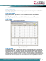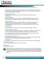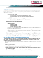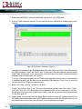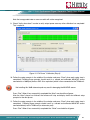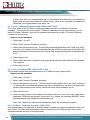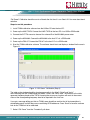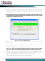
1
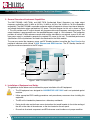
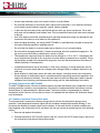
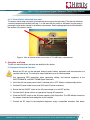
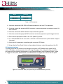
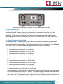
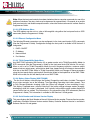
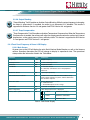
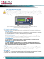
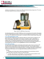
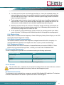
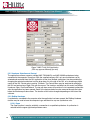
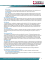
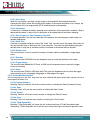
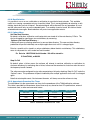
Analog Devices Welcomes
Hittite Microwave Corporation
NO CONTENT ON THE ATTACHED DOCUMENT HAS CHANGED
www.analog.com
www.hittite.com
THIS PAGE INTENTIONALLY LEFT BLANK
HMC-T2220/40/70
HMC-T2220B
HMC-T2200 Synthesized Signal Generator Family
131302 Rev H - v07.0512
Analog, Digital & Mixed-Signal ICs, Modules, Subsystems & Instrumentation
ECN# CP120624
User Manual
Installation, Operation & Maintenance Guide
for HMC-T2220, HMC-T2220B, HMC-T2240, and HMC-T2270
HMC-T2220/40/70
HMC-T2220B
Order On-Line at: www.tm-hittite.com
Receive the latest product releases - click on “My Subscription”
2 Elizabeth Drive • Chelmsford, MA 01824
978-250-3343 tel • 978-250-3373 fax • [email protected]
HMC-T2200 Synthesized Signal Generator Family User Manual
131302 Rev H - v07.0512
Table of Contents
1. Introduction. . . . . . . . . . . . . . . . . . . . . . . . . . . . . . . . . . . . . . . . . . . . . . . . . . . . . . . . . . . . . . . . . . . . . . . . . . . . . 3
2. Package Contents . . . . . . . . . . . . . . . . . . . . . . . . . . . . . . . . . . . . . . . . . . . . . . . . . . . . . . . . . . . . . . . . . . . . . . . 3
3. General Overview of Instrument Capabilities . . . . . . . . . . . . . . . . . . . . . . . . . . . . . . . . . . . . . . . . . . . . . . . . . 4
4. Installation of Equipment and Safety. . . . . . . . . . . . . . . . . . . . . . . . . . . . . . . . . . . . . . . . . . . . . . . . . . . . . . . . 4
4.1 Safety Precautions for Lithium Ion Battery Packs (HMC-T2220B). . . . . . . . . . . . . . . . . . . . . . . . . . . . . . . 5
4.2 Safety Features of the HMC-T2220B. . . . . . . . . . . . . . . . . . . . . . . . . . . . . . . . . . . . . . . . . . . . . . . . . . . . . 6
5. Operation and Setup. . . . . . . . . . . . . . . . . . . . . . . . . . . . . . . . . . . . . . . . . . . . . . . . . . . . . . . . . . . . . . . . . . . . . . 7
5.1 Equipment Setup and Operation . . . . . . . . . . . . . . . . . . . . . . . . . . . . . . . . . . . . . . . . . . . . . . . . . . . . . . . . 7
5.2Hardware Interfaces. . . . . . . . . . . . . . . . . . . . . . . . . . . . . . . . . . . . . . . . . . . . . . . . . . . . . . . . . . . . . . . . . . 8
5.3 Environmental Requirements . . . . . . . . . . . . . . . . . . . . . . . . . . . . . . . . . . . . . . . . . . . . . . . . . . . . . . . . . . 15
5.4 Fan Air Inlets . . . . . . . . . . . . . . . . . . . . . . . . . . . . . . . . . . . . . . . . . . . . . . . . . . . . . . . . . . . . . . . . . . . . . . . 15
5.5 GUI Instrument control. . . . . . . . . . . . . . . . . . . . . . . . . . . . . . . . . . . . . . . . . . . . . . . . . . . . . . . . . . . . . . . . 15
5.6 Software Installation. . . . . . . . . . . . . . . . . . . . . . . . . . . . . . . . . . . . . . . . . . . . . . . . . . . . . . . . . . . . . . . . . 20
6. Maintenance . . . . . . . . . . . . . . . . . . . . . . . . . . . . . . . . . . . . . . . . . . . . . . . . . . . . . . . . . . . . . . . . . . . . . . . . . . . 20
6.1 Instrument Calibration . . . . . . . . . . . . . . . . . . . . . . . . . . . . . . . . . . . . . . . . . . . . . . . . . . . . . . . . . . . . . . . . 20
6.2Field Power Calibration. . . . . . . . . . . . . . . . . . . . . . . . . . . . . . . . . . . . . . . . . . . . . . . . . . . . . . . . . . . . . . . 21
6.3External Cleaning . . . . . . . . . . . . . . . . . . . . . . . . . . . . . . . . . . . . . . . . . . . . . . . . . . . . . . . . . . . . . . . . . . . 30
7. Programming . . . . . . . . . . . . . . . . . . . . . . . . . . . . . . . . . . . . . . . . . . . . . . . . . . . . . . . . . . . . . . . . . . . . . . . . . .
8. Technical Support. . . . . . . . . . . . . . . . . . . . . . . . . . . . . . . . . . . . . . . . . . . . . . . . . . . . . . . . . . . . . . . . . . . . . . .
9. Warranty. . . . . . . . . . . . . . . . . . . . . . . . . . . . . . . . . . . . . . . . . . . . . . . . . . . . . . . . . . . . . . . . . . . . . . . . . . . . . .
10. Appendix . . . . . . . . . . . . . . . . . . . . . . . . . . . . . . . . . . . . . . . . . . . . . . . . . . . . . . . . . . . . . . . . . . . . . . . . . . . . .
30
30
30
31
Notice
Hittite Microwave Corporation has prepared this manual for use by Hittite personnel and customers as a
guide for the proper installation, operation, and maintenance of Hittite equipment and computer programs.
The drawings, specifications, and information contained herein are the property of Hittite Microwave Corporation, and any unauthorized use or disclosure of these drawings, specifications, and information is prohibited;
they shall not be reproduced, copied, or used in whole or in part as the basis for manufacture or sale of the
equipment or software programs without the prior written consent of Hittite Microwave Corporation.
2
Order On-Line: www.tm-hittite.com. For technical application questions: Phone: 978-250-3343 or [email protected]
131302 Rev H - v07.0512
HMC-T2200 Synthesized Signal Generator Family User Manual
1.Introduction
This User’s Manual describes the HMC-T2200 Synthesized Signal Generator Family units (SG). Most of the
pertinent information can be quickly located through the table of contents and highlighted sections.
The following conventions and indicators are used in this user’s guide:
This indicator calls attention to critical or important information, concerning an operation or
maintenance procedure or practice, which if not strictly followed and observed, could potentially
result in serious injury to operating personnel. An example is the proximity of high AC line voltage.
This indicator draws attention to a situation relating to the equipment set-up, operating or
maintaining the equipment, which if not observed, could result in permanent damage to sensitive
microwave devices or other electronic components.
This indicator highlights a required equipment preparation, fundamental procedure, practice,
condition or statement. Other indicators in bold Blue capital lettering emphasize important points
of information, input or output connections and signal generator specification headings.
The following nomenclature is affixed to the signal generator front and back panels:
HITTITE MODEL NUMBER: HMC-T2200 four-digit alphanumeric, front panel.
This user’s guide should be thoroughly read in depth and reviewed again completely before
attempting to unpack, install or operate the SG unit.
2. Package Contents
The SG unit and packaging material weigh approximately 8 lbs. Before unpacking, check for any
physical damage to the shipping container. If any noticeable damage is observed, immediately
contact Hittite Microwave Corporation. Carefully open the shipping container and inspect the SG
unit for any visible signs of damage. Save the shipping container to repackage the SG unit, or
for submitting necessary damage claims to the transporter. Remove the documentation packet
and any other separately supplied components before attempting to remove the SG unit from the
shipping container. It is highly recommended as a preventative measure, to exercise antistatic
safeguards when handling the SG unit.
Verify that all of the following components are included with the shipment:
Item
Quantity
HMC-T2220(B)/40/70 Signal Generator
1
AC Wall Power Supply
1
AC Power Cord
1
CD ROM (Contains User manuals and software)
1
Calibration Certificate
1
HMC-T2200 Family Quick Start Guide
1
LI-ION Battery Packs (HMC-T2220B only)
2
Table 1. Packing List
Order On-Line: www.tm-hittite.com. For technical application questions: Phone: 978-250-3343 or [email protected]
3
131302 Rev H - v07.0512
HMC-T2200 Synthesized Signal Generator Family User Manual
3. General Overview of Instrument Capabilities
The HMC-T2220(B), HMC-T2240, and HMC-T2270 Synthesized Signal Generators are single output
frequency synthesizers with 10 MHz to 20 GHz, 10 MHz to 40 GHz, and 10 MHz to 70 GHz bandwidths
respectively. The HMC-T2220B is a portable synthesizer which will operate for 4 hours from internal batteries,
and charge the batteries when operated from AC power. The block diagram for this unit is shown in figure
1. This unit provides one RF output channel with programmable output frequency and output power. The
output frequency is programmable over the specified frequency range, in 1 Hz increments. The synthesizer
provides an internal 10 MHz reference source which can be overridden by an external source. An AC wall
type power supply is provided to generate the required DC power for the unit. The detailed performance
specifications for the synthesizers are listed in the datasheet on the Hittite website.
The user may control the frequency, power, and RF Standby functions from either the Front Panel or the
peripheral interfaces which include a USB, Ethernet and GPIB interface. The RF Standby function will
apply the maximum attenuation to the RF output.
FRONT PANEL
I/O
SYNTHESIZER
GPIB
ENET
USB
RS232
Trigger In
CONTROLLER
SYNTHESIZER
RF
OUT
I/O
CONTROLLER
Trigger Out
10 MHz
TCXO
10 MHz
REFIN
10 MHz
REFOUT
PLL
PLL
POWER
CONTROL
+12 VDC
Figure 1. HMC-T2220/40/70 Block Diagram
4. Installation of Equipment and Safety
The guidelines shown below must be followed for proper installation of the SG equipment:
4
•
The SG equipment was designed for LABORATORY USE ONLY and is not protected against
moisture.
•
Utilize appropriate ESD handling procedures and precautionary measures when installing this
equipment.
•
The SG unit is intended for placement on a laboratory workbench.
•
During install make certain there are no obstructions that would impede air flow to the venting of
the unit on the sides of the enclosure, or the fans located on the rear panel.
•
Ensure that all external components and RF/microwave coaxial cables are in proper condition.
Order On-Line: www.tm-hittite.com. For technical application questions: Phone: 978-250-3343 or [email protected]
131302 Rev H - v07.0512
HMC-T2200 Synthesized Signal Generator Family User Manual
•
A grounded, three pin AC power receptacle shall be used to connect power to the AC wall power
supply. It is recommended that the ON/OFF power switch on the front panel be used to interrupt
power to the unit. Interrupting power by pulling out the AC cord may result in injury or unit damage.
•
The detachable AC power cord, and the power switch on the front panel must be easily accessible
to facilitate removal of power from the unit.
•
Verify the facility AC line voltage is within specifications before applying power to the unit, or the
applied DC power source is within the specifications of the unit. See paragraph. 5.2.6 to determine
the acceptable input AC voltage, and frequency range.
•
The DC power connector has GND pins which connect to the chassis. Both of these must be
connected to GND for safe operation of the unit.
4.1Safety Precautions for Lithium Ion Battery Packs (HMC-T2220B)
WARNING:
These safety instructions and the separately provided instructions of the battery manufacturer must be read carefully and must be fully understood before attempting use. Misusing the battery may cause the battery to get hot, rupture, ignite, or explode. Be sure to follow all of the safety rules listed below. Failure to do so may cause serious injury or damage to equipment.
CAUTION
• Use only battery packs supplied by Hittite Microwave Corporation in the HMC-T2220B.
• Remove batteries when packaging the unit for shipment.
• Do not place the battery on or near fires, stoves, or other high-temperature locations, as that could
cause the battery to rupture, ignite or explode.
• Do not install the battery backwards so that the polarity is reversed.
• Do not connect the positive terminal and the negative terminal of the battery to each other with any
metal object (such as wire), as a short circuit and resulting fire of batter damage may occur.
• Do not carry or store the batteries together with necklaces, hairpins, or other metal objects, as a
short circuit and resulting fire of batter damage may occur.
• Do not pierce the battery with nails, strike the battery with a hammer, step on the battery, or
otherwise subject it to strong impacts or shocks.
• Do not solder directly on the battery.
• Do not expose the battery to water or salt water, or allow the battery to get wet.
• Do not disassemble or modify the battery. The battery contains safety and protection devices
which, if damaged, may cause the battery to generate heat, rupture or ignite.
• Do not place the battery in direct sunlight or store the battery inside cars in hot weather. Doing so
may cause the battery to generate heat, rupture, or ignite. Using the battery in this manner may also
result in a loss of performance and a shortened life expectancy.
• Do not discharge the battery using any device other than the HMC-T2220B synthesized signal
generator. If the battery is used in devices aside from the specified device it may affect the performance of the battery or reduce its life expectancy, and if the device causes an abnormal current to
flow, it may cause the battery to become hot, rupture, or ignite and cause serious injury.
Order On-Line: www.tm-hittite.com. For technical application questions: Phone: 978-250-3343 or [email protected]
5
HMC-T2200 Synthesized Signal Generator Family User Manual
131302 Rev H - v07.0512
• Always keep the battery pack out of reach of infants or small children.
• Do not place the battery in microwave ovens, high-pressure containers, or on induction cookware,
as this could cause the battery to get hot, rupture, ignite or explode.
• In the event that the battery leaks and the fluid get into one’s eye, do not rub the eye. Rinse well
with water and immediately seek medical care. If left untreated the battery fluid could cause damage
to the eye.
• Use of the battery outside the specified devices operating temperature range may damage the performance of the battery or may reduce its life expectancy.
• When charging the battery, use only the HMC-T2220B or a specified battery charger ensuring that
the battery charging conditions specified are met.
• Do not attach the battery to a power supply plug or directly to a car’s cigarette lighter.
• Do not continue charging the battery if it does not recharge within the specified charging time. Doing so may cause the battery to become hot, rupture, or ignite.
• The temperature range over which the battery can be charged is +5°C to +35°C. Charging the battery at temperatures outside of this range may cause the battery to become hot or to break. Charging the battery outside of this temperature range may also harm the performance of the battery or
reduce the battery’s life expectancy.
• Immediately discontinue use of the battery if, while using, charging, or storing the battery, the battery emits an unusual smell, feels hot, changes color, changes shape, or appears abnormal in any
other way.
• Never dispose of used battery packs with other solid wastes, since they contain toxic substances.
Always dispose of used battery packs in accordance with the prevailing community regulations that
apply to the disposal of batteries. Cover the metal terminals with insulating tape in order to prevent
accidental short-circuiting, and hence possible heating and fire, when disposing of the battery.
4.2Safety Features of the HMC-T2220B
The HMC-T2220B contains 2 thermal shutdown features to protect the batteries from a potentially un-safe
operating condition caused by over-temperature. One feature is implemented within the software, and the
second feature is implemented with a thermal switch. The thermal switch is implemented as a backup
mechanism for the software. In the majority of cases it is expected that the software will disable the output
from the batteries.
4.2.1 Software Controlled Thermal Shut-down
The microcontroller, located on the battery charger board, monitors the temperature during normal
operation. If the temperature becomes higher than the shutdown temperature threshold (50 deg. C), the
microcontroller disables the power output from the battery. In the event that this shutdown condition has
been triggered, after allowing the unit to cool down, the user can recover by performing one of the following
actions:
1. Remove and replace the batteries.
2. Connect the external 12V DC power supply to the unit, turn on the 12V DC power supply, and turn on
the synthesizer using the front panel power switch.
6
Order On-Line: www.tm-hittite.com. For technical application questions: Phone: 978-250-3343 or [email protected]
131302 Rev H - v07.0512
HMC-T2200 Synthesized Signal Generator Family User Manual
4.2.2 Thermal Switch Controlled Shut-down
The thermal switch when activated, will disable the power output from the battery. The thermal switch has
a nominal temperature threshold of 65 deg. C. In the event that this switch is activated it may be reset by
pressing the reset button located in the battery compartment. See the photograph below which identifies
the location of the thermal switch.
Figure 2. View of thermal switch reset button in T2220B battery compartment
5. Operation and Setup
The SG unit control features and setup are detailed in this section.
5.1Equipment Setup and Operation
Before the SG unit can be operated, external coaxial cables, equipment and instrumentation are
required to be set-up. The instruction steps listed below must first be completed:
1. Use appropriate ESD precautions when connecting cabling, and external equipment to the
HMC-T2220/40/70, and HMC-T2220B Signal Generators.
2. Verify that the front panel power switch is switched to the “OFF” (Button not depressed) position.
3. Connect DC power cable to rear panel (DIN style DC power connector).
4. Ensure that the ON/OFF switch on the AC power adapter is in the OFF position.
5. Connect the AC power cable to an appropriate 3 prong AC receptacle.
6. Place the ON/OFF switch on the AC power adapter in the ON position. The LED indicator located on
the adapter should be illuminated green in this condition.
7. Connect the RF output to the peripheral equipment using a compatible connector. See below:
Order On-Line: www.tm-hittite.com. For technical application questions: Phone: 978-250-3343 or [email protected]
7
HMC-T2200 Synthesized Signal Generator Family User Manual
Model
Connector
HMC-T2220
SMA (F)
HMC-T2240
2.92 mm (F)
HMC-T2270
1.85 mm (F)
131302 Rev H - v07.0512
Table 2. RF Connectors
8. If desired, connect the USB, GPIB, or Ethernet connectors to the Host PC or equivalent.
9. If desired, connect the appropriate BNC connectors to external equipment to provide an external 10
MHz reference.
10.If desired, connect the 10 MHz reference input to external equipment.
11.If desired, connect the appropriate BNC connectors to external equipment to provide trigger functions.
12.Press the front panel power switch to the “ON” (labeled 1) position.
13.It is recommended that the user allows a minimum of 30 minutes warm-up time before using the
instrument.
14.Verify the unit is powered on by monitoring the front panel LCD display.
15.Using either the Front Panel Controls or the peripheral interfaces, control the operation of the SG.
5.2Hardware Interfaces
The front panel of the unit contains a multi-function rotary knob, an RF Standby switch, power On/Off
switch, LCD display, and the connector for the RF output. See figure 2 for a view of the front panel. The
rear panel of the unit contains the connectors for the External Reference Input, Reference Output, Trigger
In, Trigger Out, DC power, GPIB, Ethernet, and USB interface. See figure 3 for a view of the rear panel.
Figure 3. Front Panel View (Front panel may be labeled differently per unit)
8
Order On-Line: www.tm-hittite.com. For technical application questions: Phone: 978-250-3343 or [email protected]
131302 Rev H - v07.0512
HMC-T2200 Synthesized Signal Generator Family User Manual
Figure 4. Rear Panel View (Rear panel may be labeled differently per unit)
5.2.1 RF Output Standby
The RF output connector is located on the front panel. The RF output may be commanded to the Standby
State by either the RF Standby switch on the front panel, or by commanding the unit via one of the
peripheral interfaces. When in the Standby State, the output power attenuators are set for maximum
attenuation. The RF output specifications are located in the data sheet on the Hittite website. Please
note that while the SG unit is in the Standby state, there is still a minimal level of RF power at the signal
generator RF output.
5.2.2 Front Panel Rotary Control Knob
The large rotary knob on the front panel is used to control the synthesizer’s frequency and power output.
When the knob is depressed it will cycle through its two functions. One function selects the frequency or
power field that the user wants to adjust. The second function allows the user to adjust the value of the field
by turning the knob. The frequency and power adjustment fields consist of the following:
1. Increment/Decrement frequency with 1 Hz steps
2. Increment/Decrement frequency with 10 Hz steps
3. Increment/Decrement frequency with 100 Hz steps
4. Increment/Decrement frequency with 1 kHz steps
5. Increment/Decrement frequency with 10 kHz steps
6. Increment/Decrement frequency with 100 kHz steps
7. Increment/Decrement frequency with 1 MHz steps
8. Increment/Decrement frequency with 10 MHz steps
9. Increment/Decrement frequency with 100 MHz steps
10.Increment/Decrement frequency with 1 GHz steps
11.Increment/Decrement Output Power with 0.1 dB steps
12.Increment/Decrement Output Power with 1.0 dB steps
The front panel knob is also used to access alternate LCD display menus. These menus may be accessed
by pressing and holding the knob for 1.5 seconds. To navigate through the alternate menus the user will
rotate the knob to select the field of interest, and then depress the knob to select. To return to a previous
menu, select “BACK” and depress the knob. To return to the main LCD display, press and hold the knob
for 1.5 seconds. See paragraphs 5.2.2.1 through 5.2.2.7 for additional information.
Order On-Line: www.tm-hittite.com. For technical application questions: Phone: 978-250-3343 or [email protected]
9
HMC-T2200 Synthesized Signal Generator Family User Manual
131302 Rev H - v07.0512
Note: When the front panel controls have been locked out due to computer commands via one of the
peripheral interfaces, the rotary knob may be depressed for approximately 1.5 seconds to re-enable
front panel controls, and disable computer controls, unless the Lockout command is in effect. See the
Programmers Guide.
5.2.2.1 GPIB Address Menu
The GPIB address can be set to a value of 0 through 30 using either the front panel knob or SCPI
commands (See the Programmer’s Guide).
5.2.2.2 Ethernet Configuration Menu
The following Ethernet parameters may be configured via the front panel knob or SCPI commands
(See the Programmer’s Guide). Configuration through the front panel is available in SW Version 2.3
and greater.
1. DHCP: ON/OFF
2. IP Address
3. Network Mask
4. Port Number
5.2.2.3 T2100 Compatibility Mode Menu
Any HMC-T22XX containing SW Version 2.2 or greater can be set to T2100 Compatibility Mode via
SCPI commands (See the Programmer’s Guide) or the front panel knob (SW Version 2.3 and up).
When a unit is set to T2100 Compatibility Mode, the unit’s frequency resolution, maximum output
power, minimum output power, and minimum dwell time (sweep timing) will change to be consistent
with that of the HMC-T2100. While in T2100 Compatibility Mode, any changes to these parameters
using the front panel display and knob will likewise be limited to the capabilities of the HMC-T2100.
While in this mode, the unit will identify itself as an HMC-T2100.
5.2.2.4 Battery Status Display (HMC-T2220B)
The first line of battery status displays the Percent Charged for each battery installed. The second
line of status contains one of the following: Time Remaining (Operating from battery power), Time
to Fully Charged (Batteries charging), blank line (Either fully charged, or time remaining is zero).
This display is updated once a second. Note that if the battery charger changes modes (charging,
discharging) while this screen is displayed, it will typically take multiple screen updates before the
second status line has settled. This information is also accessible using SCPI commands (See the
Programmer’s Guide). This information is available for SW Versions 2.3 and greater.
5.2.2.5 Serial Number and Software Version Display
This menu displays the Serial Number of the unit, Software Version number, Firmware Version number,
and Battery Controller Software Version number. Battery Controller Software Version is available in
Software Version 2.3 and greater.
10
Order On-Line: www.tm-hittite.com. For technical application questions: Phone: 978-250-3343 or [email protected]
131302 Rev H - v07.0512
HMC-T2200 Synthesized Signal Generator Family User Manual
5.2.2.6 Output Blanking
”Output Blanking” On/Off enables or disables Output Blanking. While the output frequency is changing,
the output is attenuated if it’s enabled, the output is not attenuated if it’s disabled. This feature is
supported for Software Version 2.3 and greater and FPGA Version 4.6 and greater.
5.2.2.7 Temp Compensation
”Temp Compensation” On/Off enables or disables Temperature Compensation. When the Temperature
Compensation is enabled, the software will adjust the output power based on the synthesizer’s internal
temperature, so the output power will stay relatively stable. This feature is supported for SW Version
2.4 and greater and FPGA Version 5.1 and greater.
5.2.3 Front Panel Frequency & Power LCD Display
5.2.3.1 Main Screen
At power turn-on the LCD will display the units Serial Number, Model Number, as well as the firmware
revision. Sometime thereafter the LCD will change to display its operational state. The operational
state provides the information listed in the Table below.
Function
Units
Frequency
Hz
RF Output Power
dBm
Comments
Output Frequency
Commanded Output Power
RF Status
N/A
Output ON or OFF
Unit Status
N/A
L – PLL loss of lock
R – Remotely controlled via one of the peripheral
interfaces.
Reference Source
N/A
I (Internal) E (External)
Selected Function Indicator
N/A
Underlined character indicates which field the rotary
knob controls frequency or power, and this determines
the resolution step size.
RF Power Status
N/A
Blank – Output Power Leveled
C- Calibration Error
* - Commanded power is out of range
Fan Failure
N/A
“Fan Fault” is displayed
Over Temperature
N/A
“Over Temperature Fault” is displayed
Battery Status (HMC-T2220B only)
N/A
PRSNT
BATTERY PRESENT
CHRG
BATTERY CHARGING
LOW
BATTERY LOW
Table 3. Front Panel Display
Order On-Line: www.tm-hittite.com. For technical application questions: Phone: 978-250-3343 or [email protected]
11
HMC-T2200 Synthesized Signal Generator Family User Manual
131302 Rev H - v07.0512
5.2.3.1.1 Front Panel Power Level Status
The HMC-T2220/40/70, and HMC-T2220B includes a power level indicator on the Front Panel display
which can be monitored by the user to determine if the output power specified by the user is within
the instruments calibrated output range (See the data sheet). When the instrument is commanded to
a Frequency and Power combination which is beyond the units specified calibration range, the “ * ”
indicator will appear on the display.
*
Figure 5.HMC-T2220/40/70 and HMC-T2220B Un-calibrated Output Power Indicator
(Front panel may be labeled differently per unit)
5.2.4 Computer Peripheral Interfaces
The synthesizer’s status and programmable functions are identified in the Programmer’s guide document.
5.2.4.1 USB Interface
The USB connector is located on the rear panel. The USB interface is compliant with USB 1.1, and USB
2.0. The mating connector for this unit is a USB Series B plug style connector.
5.2.4.2 Ethernet Interface
The Ethernet connector is located on the rear panel. The mating connector is a standard RJ-45 plug
style connector. The Ethernet interface is a 10/100 Base T interface.
5.2.4.3 GPIB Interface
The GPIB connector is located on the real panel. The mating connector is a standard 24 pin male
connector. The GPIB interface is compliant with IEEE 488.2.
5.2.4.4 RS232 Interface
The RS-232 connector is a modular phone jack. This interface is not recommended because of its
speed, but is informally supported for customers wishing to control the T2200 from a microcrontroller or
FPGA. Please contact Hittite for pinout and other information.
5.2.5 Trigger In
The Trigger In, is an input only signal which connects to a BNC connector on the rear panel. This input is
compatible with TTL signal levels. When the external trigger is enabled by software, the rising edge of the
signal will trigger a sweep function. See the Programmers Guide for more information.
5.2.6 Trigger Out
The Trigger Out, is an output only signal which connects to a BNC connector on the rear panel. This output
is compatible with TTL signal levels. See the Programmers Guide for more information.
12
Order On-Line: www.tm-hittite.com. For technical application questions: Phone: 978-250-3343 or [email protected]
131302 Rev H - v07.0512
HMC-T2200 Synthesized Signal Generator Family User Manual
5.2.7 External Reference/Internal Reference
5.2.7.1 Internal Reference Out
The HMC-T2220/40/70, and HMC-2220B Signal Generator includes an internal precision 10 MHz
reference. The performance of this reference output is specified in the datasheet on the Hittite website.
The 10 MHz reference output is located on the rear panel BNC connector.
5.2.7.2 External Reference In
The internal reference can be overridden by connecting an external reference to the BNC connector
located on the rear panel. The unit automatically detects and uses the external reference if present,
unless overriden by the ROSC commands (see the Programmers Guide).
5.2.8 Power Input
The unit is powered using the supplied AC wall supply.
5.2.8.1 AC Power adapter
The AC power adapter will operate from a single phase AC source of 100 to 240 VAC, with a frequency
of 47 - 63 Hz. The AC power adapter automatically adjusts to the connected power source. A power
cable is provided with each unit. The appropriate cable must be selected from the available options in
the data sheet when ordering. The AC power adapter contains a power switch, and a power on indicator
LED.
5.2.8.2 Power On/Off
Power is turned On/Off with the switch located on the front panel of the enclosure.
5.2.9 Battery Unit (HMC-T2220B)
The HMC-T2220B can be fitted with single or dual Lithium-Ion battery packs which make it independent of
an external power source. The unit can be operated for approximately 2 hours with a single battery, and up
to 4 hours with 2 batteries before the battery packs require recharging. Status indicators on the front panel
display monitor the battery status. The battery packs inside the HMC-T2220B will be charged whenever the
external power supply is connected. When powered ON, the unit may be operated normally while charging
the battery packs concurrently. Typical charging time for each battery pack is approximately 6 hours, and
dual batteries are charged concurrently. Battery performance and life will be affected by temperature and
number of recharge cycles
5.2.9.1 Safety Summary
Please carefully read and follow all warnings and cautions in this document before handling and
operating the HMC-T2220B and battery packs. Serious injury and equipment failures may occur if the
safety warnings and cautions are not followed.
CAUTION:
Only battery packs supplied by Hittite Microwave Corporation can be used in the HMC-T2220B.
Remove batteries when packaging the unit for shipment.
5.2.9.2Battery Installation
Disconnect the external power supply cable from the back of the HMC-T2220B.
To install either one or two of the lithium-ion battery packs, simply remove the top cover by loosening
the two captive screws. Prior to installation, battery charge status can be checked by depressing the
Order On-Line: www.tm-hittite.com. For technical application questions: Phone: 978-250-3343 or [email protected]
13
HMC-T2200 Synthesized Signal Generator Family User Manual
131302 Rev H - v07.0512
red button on the battery pack. A series of four LEDs will indicate the battery charge status. This status
may also be checked in the same manner once installed.
Figure 6.HMC-T2220B Battery Compartment
Insert the battery pack(s) into the HMC-T2220B and verify that the battery pack connector fully engages
the HMC-T2220B receptacle connector. Reinstall the cover and tighten the two captive screws. The unit
is now ready to be operated from battery power. If so desired, re-install the external power supply cable.
5.2.9.3 Operating on Battery Power
Operate the HMC-T2220B normally until the battery indicator on the front panel LCD indicates a low
battery warning. You should be able to use the unit for an average of 2 hours, (single battery), or
4 hours, (dual batteries) when batteries are new without having to recharge. Once the battery low
condition occurs, you should have approximate 5-10 minutes of operation until the internal power
monitoring circuitry will automatically shut down the unit to prevent over discharging the batteries. It is
recommended that the batteries be re-charged before the automatic shutdown engages.
5.2.9.4 Battery Charging
The battery pack(s) are charged by connecting the external power supply to the rear of the unit. With
the external power supply turned off, insert the battery(s) into the unit. Turn on the external power
supply. Turn on the unit with the front panel power button. The battery present indicator should be on, or
the battery charging indicator will be on when the battery(s) are charging. The battery charging indicator
will go off when the battery(s) are fully charged and the battery present indicator will be on.
NOTES:
1. The battery unit will shut itself off. Under normal operation at the manufacturers minimum
operating voltage, preventing the battery from being discharged.
2. If a battery pack becomes over discharged, or the battery pack’s internal protection circuits
have been activated, battery charge time may be longer than typical.
14
Order On-Line: www.tm-hittite.com. For technical application questions: Phone: 978-250-3343 or [email protected]
131302 Rev H - v07.0512
HMC-T2200 Synthesized Signal Generator Family User Manual
3. If a battery pack has been over discharged resulting in a lower than expected voltage, the
battery charging circuit may not turn on when the battery is inserted into the unit while operating
from the external power supply. In this event, the external power supply should be turned off
before inserting the battery(s).
4. The charging circuits include an internal safety timer. Under normal conditions charging time
will be less than 7 hours. In the event that battery charging time is greater than 8 hours, the
battery(s) are considered defective and should be replaced and properly disposed.
5. Batteries may be left in the unit at all times. The battery charger will charge and maintain the
battery(s) level as long as the external power supply is on. If the battery pack(s) are left on the
shelf, the battery charge level will reduce over time.
6. As the number of charge and discharge cycles increase, the operating duration from battery
power will reduce. The battery pack should be disposed of to the appropriate recycling agency.
5.2.9.5 Battery Status
Battery status is available from the Frequency & Power LCD display, Battery Status Display, or via SCPI
commands (See the Programmer’s Guide).
5.2.9.6 Battery Storage Recommendations
The batteries should be stored at room temperature, charged to about 30 to 50% of capacity. It is
recommended that the batteries be charged at least once a year to prevent over-discharge.
5.2.9.7 Replacement Batteries
Replace batteries with Lithium-Ion batteries, Honeywell Batteries part number HD220R-Li. These
batteries may be purchased through Hittite, as Hittite part number HMC-T2220B-BATTERY.
5.3Environmental Requirements
The unit is designed to be operated in an environment meeting the following requirements:
Environment Condition
Value
General Usage
Indoors
Temperature
0 to 35 degrees C
Humidity
15% to 95% non-condensing (See Datasheet)
Altitude
Less than 3000 meters
Table 4. Environmental Operating Conditions
5.4Fan Air Inlets
The unit utilizes fans, mounted on the rear panel for cooling. Please ensure that the fans, and vent
openings are not obstructed or the unit may overheat and damage may result.
5.5GUI Instrument control
The instrument may be controlled from a computer using the Hittite Supplied GUI application. The features
of the GUI are described in this section. A picture of the GUI is shown in figure 7.
Order On-Line: www.tm-hittite.com. For technical application questions: Phone: 978-250-3343 or [email protected]
15
HMC-T2200 Synthesized Signal Generator Family User Manual
131302 Rev H - v07.0512
Figure 7.HMC-T2200 GUI Application
(GUI may appear differently per unit)
5.5.1 Hardware Selection and Control
The application software supports multiple HMC-T2220/40/70, and HMC-2220B synthesizers being
connected to the computer at one time. With the supplied software GUI, only one synthesizer can be
selected and controlled from the GUI application at one time. Multiple synthesizers can be controlled by
changing the selected synthesizer from the drop-down list at the top of the GUI, or by launching multiple
copies of the GUI. Please refer to section 7.0 herein. The Control Menu may be accessed by pointing to
the GUI and performing a Right Click with the mouse. The functions available from this menu are ReMap
Hardware, Open, Close and Refresh. The top pull-down menu will provide a list of connected synthesizers
after the application has been opened. Some of the features below may be accessed through the button
below the hardware pull-down menu. The function of this button changes depending on the state of the
software.
5.5.2 ReMap Hardware
If synthesizers are added to the computer after the application has been opened, the ReMap Hardware
function may be used to force the computer to go and check for any new synthesizer units.
5.5.2.1 Open
The Open function is used to establish a connection to a specified synthesizer. A synthesizer is
selected with the upper right hand pull-down menu.
16
Order On-Line: www.tm-hittite.com. For technical application questions: Phone: 978-250-3343 or [email protected]
131302 Rev H - v07.0512
HMC-T2200 Synthesized Signal Generator Family User Manual
5.5.2.2 Close
The Close function is used to disconnect the currently selected synthesizer. A new synthesizer may
then be selected with the upper right hand pull-down menu, and the Open function.
5.5.2.3 Refresh
Once a synthesizer has been selected with the Open command, the Refresh function may be used
to read the current status of the synthesizer. If the GUI checkbox for Remote and Local Lockout has
not been checked, the Refresh function will read the current status of the unit as commanded via the
synthesizer’s front panel.
5.5.3 Synthesizer Selection Menu
This is a pull-down menu at the top right hand side of the GUI. All synthesizers which have been detected
by the software are displayed in this menu. If synthesizers are added to the computer after the application
has been started, use the ReMap Hardware function to force the software to check for other synthesizers.
5.5.4 Remote
The Remote feature is enabled by a checkbox available within the GUI. When the checkbox is selected,
computer controlled operation via the USB is enabled. If this checkbox is not selected, the software
application will not change any settings in the synthesizer. However in this state, if the Refresh button is
depressed, the current Frequency and Power fields will be updated with the current settings within the
synthesizer.
5.5.5 Local Lockout
The Local Lockout feature is enables by a checkbox within the GUI. When the checkbox is selected, local
control from the front panel will not resume after pressing and holding the rotary knob for at least 1.5
seconds.
5.5.6 Frequency Field
The Frequency of the synthesizer may be controlled with the text box. The desired frequency can be
typed into the provided text box. Also, the up and down arrows on the keyboard and next to the GUI field
may be used to increment or decrement the frequency by the amount indicated in the Step box. After
a new frequency has been entered, the application attempts to set the synthesizer to the commanded
frequency. If the specified frequency is out of range or contains non-numeric characters, the field will be
highlighted in yellow.
5.5.7 Power field
The power of the synthesizer may be controlled with the text box. The desired power can be typed into the
provided text box. Also, the up and down arrows on the keyboard and next to the GUI field may be used to
increment or decrement the frequency by the dBm indicated in the Step box. After a new power level has
been entered, the application attempts to set the synthesizer to the commanded power. If the specified
power is out of range or contains non-numeric characters, the field will be highlighted in yellow.
5.5.8 RF Output On
The RF Output On checkbox is used to enable and disable the RF output of the Signal Generator.
5.5.9 Synthesizer Frequency Sweeping Controls
The GUI provides a number of controls to allow the user to perform frequency and power sweeps.
5.5.9.1 Sweep Mode Dropdown Menu
The user can choose to sweep Frequency, Power, Frequency List, Power List, Frequency+Power List
or None using this dropdown menu.
Order On-Line: www.tm-hittite.com. For technical application questions: Phone: 978-250-3343 or [email protected]
17
HMC-T2200 Synthesized Signal Generator Family User Manual
131302 Rev H - v07.0512
5.5.9.2 Start / Stop
When the start button is pressed, a single sweep is performed with the selected parameters.
Depressing the “Stop” button will stop the current sweep. At the normal completion of any sweeps, the
unit will remain at the last programmed (STOP condition) power and frequency.
5.5.9.3 Continuous
If Continuous is selected (checked), sweeping nuns continuously for the parameters selected. If Stop is
depressed the sweep is reset to the first parameter of the sweep and then continues sweeping
5.5.9.4 Start Frequency / Stop Frequency / Step Size
For sweep operations, the user can select the start frequency, the stop frequency, and the step size
between frequencies.
5.5.9.5 Dwell Time
A text box is provided to enter the value of the “Dwell Time” for each step in the sweep. Valid values for
this field are 0.001 secs to 3600 secs with 1 µsec resolution. The value may be entered by typing the
desired value or using the up and down arrows to increment or decrement the time duration.
5.5.9.6 Sweep Count
The user can enter a value to specify the number of sweeps which are enabled by a single trigger
event.
5.5.9.7 Direction
The user can select UP/DOWN from this dropdown menu to control the direction of the sweep.
5.5.9.8 Trigger Source
The user can select IMMediate, EXTernal, or BUS from this dropdown menu to control the trigger
source of the sweep.
5.5.9.9 Slope
The user can select POSitive, NEGative and EITHer from this dropdown menu to control the trigger
event occurring on the rising edge, falling edge, or either edge of the signal.
5.5.10 ContextMenuStrip Control
Go to an empty part of your GUI, away from any icons, and click the right mouse button, and you will see a
menu open that shows a list.
5.5.10.1 Remap Hardware
Selecting “Remap Hardware” will have the same function as clicking the “Remap Hardware” button.
5.5.10.2 Open
Selecting “Open” will have the same function as clicking the”Open” button.
5.5.10.3 Refresh
Selecting “Refresh” will have the same function as clicking the “Refresh” button.
5.5.10.4 Close
Selecting “Close” will have the same function as clicking the “Close” button.
5.5.10.5 T2100 Compatible
Selecting “T2100 Compatible” will cause the unit to reboot and to go to T2100 Compatible mode;
Deselecting “T2100 Compatible” will cause the unit to reboot and to go to the Normal operation mode.
18
Order On-Line: www.tm-hittite.com. For technical application questions: Phone: 978-250-3343 or [email protected]
131302 Rev H - v07.0512
HMC-T2200 Synthesized Signal Generator Family User Manual
5.5.10.6 Dwell Time Step
Select “Set Dwell Time Step”, a text-box will appear, type the value of the step size for the Dwell Time
and press the “Enter” key.
5.5.10.7 Output Blanking
Select “Output Blanking”, then select “Off” or “On” to disable or enable the Output Blanking.
5.5.10.8 Temp Compensation
Select “Temp Compensation”, then select “Off” or “On” to disable or enable the Temperature
Compensation.
5.5.10.9 List Mode
Select “List Mode...”, a new window will be displayed:
Figure 8.List Mode GUI
5.5.10.9.1 List Mode
List Mode allows the T2200 to sweep through Frequency, Power, and Output states in any order and
with changing Dwell Times. The user can enter the values in the grid by hand or by copying them to or
from another tool such as a spreadsheet. Individual values may be left blank to indicate “no change.”
The points of the Lists are shown numbered 1 through N. When the Direction is UP, and Generation is
DSEQuence, they are executed in this order. The Time(s) are calculated automatically; editing them will
update the Dwell Time for the previous state. Blue shaded values have changed relative to the value
Order On-Line: www.tm-hittite.com. For technical application questions: Phone: 978-250-3343 or [email protected]
19
HMC-T2200 Synthesized Signal Generator Family User Manual
131302 Rev H - v07.0512
Read from the unit and indicate that you need to Write before the hardware will see these changes.
Yellow shaded values indicate a problem with the data, such as an out of range value. The “right click”
context menu may be helpful when editing.
5.5.10.9.2 Sequence List
The user can enter the index numbers which are available on the List Mode to set up the Sequence List.
5.5.10.9.3 Read/Write
When the Read button is pressed, GUI will read List Mode and Sequence List from the unit and display them on the GUI; When the Write button is pressed, GUI will write the data to the unit.
5.5.10.9.4 Save/Load
When the Save button is pressed, a dialogue will show up, user can specify the directory and file name to save List Mode and Sequence List as SCPI command; When the Load button is pressed, a dialogue will show up, user can load List Mode and Sequence List to the GUI from a specified text file.
5.5.10.9.5 Count
The user can specify the number of times the list is sequenced when a trigger is received.
5.5.10.9.6 Generation / Direction
User can select Generation mode from Dropdown List: DSEQuence mode which will execute the List
from the first to the last or SEQuence mode which will execute the List in SEQuence order.
User can select Direction from Dropdown List: UP which will execute the List from the first to the last or DOWN which will execute the List from the last to the first.
5.5.10.10 Show Sweep Parameters
Select “Show Sweep Parameters”, sweep related controls will show up on the GUI; Deselect “Show
Sweep Parameters”, sweep related controls will not show up on the GUI.
5.5.10.11 About
Select “About”, a small window will pop up to display version information and the license agreement.
5.6Software Installation
Refer to “Software Installation” section in the Quick Start Guide.
6.Maintenance
6.1Instrument Calibration
Each Signal Generator is calibrated at the factory prior to shipment, and is accompanied by a
calibration sticker and calibration certificate. For re-calibration customers can ship the unit to Hittite for
a manufacturer’s RF output power calibration (includes calibration sticker and calibration certificate)
or by following the instructions in the next section. The RF output connector should be cleaned as
needed.
20
Order On-Line: www.tm-hittite.com. For technical application questions: Phone: 978-250-3343 or [email protected]
131302 Rev H - v07.0512
HMC-T2200 Synthesized Signal Generator Family User Manual
6.2Field Power Calibration
The instrument is provided with Hittite software to calibrate the unit’s output power. Instructions for operating this software are in the next section. The supported equipment that can be used with the T2200 calibration software is as follows:
• HMC-T220 & HMC-T2240
• Anritsu ML2438A power meter with MA2474D power sensor.
• Anritsu 41KC-10 (DC - 40 GHz) 10 dB attenuator pad (or equivalent).
• HMC-T2270
• Anritsu ML2438A power meter with SC7770 power sensor.
• Rohde & Schwarz FSU-67.
Equipment for low power verification (optional):
• Spectrum Analyzer
• Agilent PSA Series
• Agilent MXA Series
• Rohde & Schwarz FSU series
(Frequency coverage to 20 GHz for the HMC-T2220, to 40 GHz for the HMC-T2240 and to to
67 GHz for the HMC-T2270 assumed)
• Cable with better than 5 dB insertion loss at maximum frequency of T2200 to connect between T2200 and spectrum analyzer.
Software version 2.4 and Hardware version 5.1 or later are required to use the T2200 calibration
software. (The firmware updater may be found on the Utilities CD along with the T2200 calibration
software). Units with previous versions of firmware may run “Verify” but not calibration procedures,
“Verify Low”, or “Restore”. The T2200 calibration software requires Windows XP (SP3) or later.
6.2.1 “Full Power” Calibration Procedure (HMC-T2220 & HMC-T2240)
This procedure does a full calibration of the output power. It executes two phases of calibration: “Atten” and
then “Offset”. The “Atten” phase calibrates the internal attenuators of the T2200 and the “Offset” phase
establishes absolute accuracy of the output power.
“Full Power” Calibration should be run for all bands the first time it is run. See 6.2.7 for more about band
selection.
Steps to run this procedure:
1. Install T2200 calibration software from the Utilities CD onto the host PC.
2. Power up the HMC-T2220 or HMC-T2240. Connect the HMC-T2220 or HMC-T2240 to the host PC
via a USB or GPIB cable.
3. Connect the MA2474D sensor to channel A or channel B of the ML2438A power meter.
Order On-Line: www.tm-hittite.com. For technical application questions: Phone: 978-250-3343 or [email protected]
21
HMC-T2200 Synthesized Signal Generator Family User Manual
131302 Rev H - v07.0512
4. Power up the ML2438A. Connect the ML2438A to the host PC via a GPIB cable.
5. Start the T2200 calibration software. The software should start and display a window like the one in
Figure 9.
Figure 9.“Full Power” Calibration (Step 5)
The table on the window should be showing green cells in the “Atten” and “Offset” rows indicating that
the T2200 already has “Atten” and “Offset” data. The columns in the table represent frequency bands
of the T2200. Hovering the cursor over a column will result in the current status of the corresponding
frequency band to be reported in the “Info” box.
If you get a message telling you that no T2200’s were found then confirm that all instrumentation
is connected properly and that there are no conflicting GPIB addresses. Press “Scan” to have the
software look for the T2200 unit to be calibrated.
6. Select “Full Power” from the “Procedure” pull-down.
7. Check “Clear previous data on run”. This will mark pre-existing (green) data in the “Atten”, “Offset”,
and “Verify” rows with a “d” indicating that it will be deleted when cal starts to make room for new data.
Not doing so will prevent a new calibration from running. Note that pre-existing data will be backed up
in a file. See figure 10.
8. Select a meter and sensor pair from the “Power Meter” pull-down. If none are available, check that the
ML2438A is connected properly with no GPIB address conflicts and that the MA2474D sensor is also
connected. Press “Scan” to have the software look for a meter/sensor pair again.
22
Order On-Line: www.tm-hittite.com. For technical application questions: Phone: 978-250-3343 or [email protected]
131302 Rev H - v07.0512
HMC-T2200 Synthesized Signal Generator Family User Manual
Note that unsupported meter or sensor models will not be recognized.
9. Check “Verify when done” in order to verify output power accuracy after calibration has completed.
This is optional.
Figure 10.“Full Power” Calibration (Step 8)
10.Follow the setup prompts in the middle of the window and press “Done” when each setup step is
completed. Following these prompts should result in a zeroed and calibrated MA2474D sensor
connected to a 10dB pad (Anritsu 41KC-10 or equivalent) which is then connected to the T2200 unit.
Not installing this 10dB attenuator pad may result in damaging the MA2474D sensor.
Press “Run”. When it has successfully completed the “Atten” row should be all green.
After the “Atten” phase has finished, the software will stop and display similar but different setup
prompts for the next phase.
11.Follow the setup prompts in the middle of the window and press “Done” when each setup step is
completed. Following these prompts should result in a zeroed and calibrated MA2474D sensor
connected directly to the T2200 unit (no attenuator pad!).
Press “Run”. When it has successfully completed the “Offset” row should be all green.
Order On-Line: www.tm-hittite.com. For technical application questions: Phone: 978-250-3343 or [email protected]
23
HMC-T2200 Synthesized Signal Generator Family User Manual
131302 Rev H - v07.0512
If “Verify when done” was checked before step 11), the software will automatically run verification of
power using the same setup used in the “Offset” phase. When it has successfully completed you
should see a row of green boxes in the “Verify” row.
6.2.2 “Offset” Calibration Procedure (HMC-T2220 & HMC-T2240)
The “Offset” phase of the “Full Power” calibration procedure can be run in isolation as a separate
procedure. This can be done to re-establish a T2200 unit’s absolute accuracy without having to run an
entire “Full Power” calibration. Note that this procedure should only be run after “Full Power” calibration
has been run at least once.
Steps to run this procedure:
1. Follow steps 1-5 in 6.2.1.
2. Select “Offset” from the “Procedure” pull-down.
3. Check “Clear previous data on run”. This will mark pre-existing (green) data in the “Offset” and “Verify”
rows with a “d” indicating that it will be deleted when the cal starts to make room for new data. Not
doing so will prevent a new calibration from running. Note that pre-existing data will be backed up in
a file.
4. Follow step 8 in 6.2.1.
5. Check “Verify when done” in order to verify output power accuracy after calibration has completed.
This is optional.
6. Follow step 11 in 6.2.1.
6.2.3 “Verify” Procedure (HMC-T2220 & HMC-T2240)
This procedure verifies the output power accuracy of a T2200 unit using a power sensor.
Steps to run this procedure:
1. Follow steps 1-5 in 6.2.1.
2. Select “Verify” from the “Procedure” pull-down.
3. Check “Clear previous data on run”. This will mark pre-existing (green) data in the “Verify” row with a
“d” indicating that it will be deleted when the cal starts to make room for new data. Not doing so will
prevent a new verification from running. Note that this data will be backed up in a file.
4. Follow step 8 in 6.2.1.
5. Follow the setup prompts in the middle of the window and press “Done” when each setup step is
completed. Following these prompts should result in a zeroed and calibrated MA2474D sensor
connected directly to the T2200 unit (no attenuator pad!).
Press “Run”. When it has successfully completed the “Verify” the row should be all green.
6.2.4 “Full Power” Calibration Procedure (HMC-T2270)
This procedure does a full calibration of the output power. It executes two phases of calibration: “Atten” and
then “Offset”. The “Atten” phase calibrates the internal attenuators of the T2200 and the “Offset” phase
establishes absolute accuracy of the output power.
24
Order On-Line: www.tm-hittite.com. For technical application questions: Phone: 978-250-3343 or [email protected]
131302 Rev H - v07.0512
HMC-T2200 Synthesized Signal Generator Family User Manual
“Full Power” Calibration should be run for all bands the first time it is run. See 6.2.11 for more about band
selection.
Steps to run this procedure:
1. Install T2200 calibration software from the Utilities CD onto the host PC.
2. Power up the HMC-T2270. Connect the HMC-T2270 to the host PC via a USB or GPIB cable.
3. Connect the SC7770 sensor to channel A or channel B of the ML2438A power meter.
4. Power up the ML2438A. Connect the ML2438A to the host PC via a GPIB cable.
5. Power up the FSU-67. Connect the FSU-67 to the host PC via a GPIB cable.
6. Start the T2200 calibration software. The software should start and display a window like the one in
Figure 11.
Figure 11.“Full Power” Calibration (Step 6)
The table on the window should be showing green cells in the “Atten”, “Offset”, and “Verify” rows indicating that the T2200 already has “Atten”, “Offset”, and “Verify” data. The columns in the table
represent frequency bands of the T2270. Hovering the cursor over a column will result in the current
status of the corresponding frequency band to be reported in the “Info” box.
If you get a message telling you that no T2200’s were found then confirm that all instrumentation is
connected properly and that there are no conflicting GPIB addresses. Press “Scan” to have the software
look for the T2200 unit to be calibrated.
7. Select “Full Power” from the “Procedure” pull-down.
Order On-Line: www.tm-hittite.com. For technical application questions: Phone: 978-250-3343 or [email protected]
25
HMC-T2200 Synthesized Signal Generator Family User Manual
131302 Rev H - v07.0512
8. Check “Clear previous data on run”. This will mark pre-existing (green) data in the “Atten”, “Offset”, and
“Verify” rows with a “d” indicating that it will be deleted when cal starts to make room for new data. Not
doing so will prevent a new calibration from running. Note that pre-existing data will be backed up in
a file. See figure 12.
9. Select a spectrum analyzer from the “Spectrum Analyzer” pull-down. If none are available, check that
the spectrum analyzer is connected properly with no GPIB address conflicts. Press “Scan” to have the
software look for the spectrum analyzer again.
Note that unsupported spectrum analyzer models will not be recognized.
Figure 12.“Full Power” Calibration (Step 9)
10.Check “Verify when done” in order to verify output power accuracy after calibration has completed.
This is optional.
11. Follow the setup prompts in the middle of the window and press “Done” when each setup step is
completed. Following these prompts should result a supported spectrum analyzer connected to the
T2270 unit through a low insertion loss (<5dB) cable.
Press “Run”. When it has successfully completed the “Atten” row should be all green up though
68GHz. The software will stop and display similar but different setup prompts for the next phase.
12.Select a meter and sensor pair from the “Power Meter” pull-down. If none are available, check that the
ML2438A is connected properly with no GPIB address conflicts and that the SC7770 sensor is also
connected. Press “Scan” to have the software look for a meter/sensor pair again.
Note that unsupported meter or sensor models will not be recognized.
26
Order On-Line: www.tm-hittite.com. For technical application questions: Phone: 978-250-3343 or [email protected]
131302 Rev H - v07.0512
HMC-T2200 Synthesized Signal Generator Family User Manual
13.Follow the setup prompts in the middle of the window and press “Done” when each setup step is
completed. Following these prompts should result in a zeroed and calibrated SC7770 sensor connected
directly to the T2270 (no attenuator pad!).
Press “Run”. When it has successfully completed the remaining “Atten” rows and all of the “Offset”
rows should all be green.
If “Verify when done” was checked before this step, the software will automatically run verification
of power using the same setup used in the “Offset” phase. When it has successfully completed you
should see a row of green boxes in the “Verify” row.
6.2.5 “Offset” Calibration Procedure (HMC-T2270)
The “Offset” phase of the “Full Power” calibration procedure can be run in isolation as a separate
procedure. This can be done to re-establish a T2270’s absolute accuracy without having to run an entire
“Full Power” calibration. Note that this procedure should only be run after “Full Power” calibration has been
run at least once assuming access to an FSU-67 is feasible.
Steps to run this procedure:
1. Follow steps 1-6 in 6.2.4.
2. Select “Offset” from the “Procedure” pull-down.
3. Check “Clear previous data on run”. This will mark pre-existing (green) data in the “Offset” and “Verify”
rows with a “d” indicating that it will be deleted when the cal starts to make room for new data. Not
doing so will prevent a new calibration from running. Note that pre-existing data will be backed up in
a file.
4. Follow step 12 in 6.2.4. (Note that “Atten” row should be already completely green)
5. Check “Verify when done” in order to verify output power accuracy after calibration has completed.
This is optional.
6. Follow step 13 in 6.2.4
6.2.6 “Verify” Procedure (HMC-T2270)
This procedure verifies the output power accuracy of a T2270 using a power sensor.
Steps to run this procedure:
1. Follow steps 1-6 in 6.2.4.
2. Select “Verify” from the “Procedure” pull-down.
3. Check “Clear previous data on run”. This will mark pre-existing (green) data in the “Verify” row with a
“d” indicating that it will be deleted when the cal starts to make room for new data. Not doing so will
prevent a new verification from running. Note that this data will be backed up in a file.
4. Follow step 12 in 6.2.1.
Order On-Line: www.tm-hittite.com. For technical application questions: Phone: 978-250-3343 or [email protected]
27
HMC-T2200 Synthesized Signal Generator Family User Manual
131302 Rev H - v07.0512
5. Follow the setup prompts in the middle of the window and press “Done” when each setup step is
completed. Following these prompts should result in a zeroed and calibrated SC7770 sensor connected
directly to the T2270 (no attenuator pad!).
Press “Run”. When it has successfully completed the “Verify” the row should be all green.
6.2.7 “Verify Low” Procedure (HMC-T2220, HMC-T2240 & HMC-T2270)
This procedure verifies the output power accuracy of a T2200 at lower powers using a spectrum analyzer.
The ‘Verify’ procedure must run and pass before this procedure can be run.
Steps to run this procedure:
1. Follow steps 1-5 in 6.2.1.
2. Select “Verify Low” from the “Procedure” pull-down. This will make the previously hidden “Verify Low”
row visible.
3. Check “Clear previous data on run”. This will mark pre-existing (green) data in the “Verify Low” and
row with a “d” indicating that it will be deleted when the cal starts to make room for new data. Not
doing so will prevent a new verification from running. Note that this data will be backed up in a file.
4. Select a spectrum analyzer for the “Spectrum Analyzer” pull-down. If none are available, check that
the spectrum analyzer is connected properly with no GPIB address conflicts. Press “Scan” to have
the software look for the spectrum analyzer again.
Note that unsupported spectrum analyzer models will not be recognized.
5. Follow the setup prompts in the middle of the window and press “Done” when each setup step is
completed. Following these prompts should result a supported spectrum analyzer connected to the
T2200 unit through a low insertion loss (<5dB) cable.
Press “Run”. When it has successfully completed the “Verify Low” the row should be all green.
6.2.8 “Restore” Procedure
The “Restore” procedure can be used to revert to previously backed-up calibration data. When “Restore” is
selected from the “Procedure” pull-down, a dialog window will appear allowing the selection of a previously
generated backup image. When the backup image is selected, it is then written into the non-volatile storage
of the T2200 unit.
Backup image files end with the suffix .t22cal and are stored in a T2200 unit’s data directory (i.e. C:\Data\
T2240_sn000123):
6.2.9 Interruptions
If a calibration or verification procedure is interrupted by the user pressing “Abort” or a power failure, a
procedure can be re-started and the software will automatically proceed from where it left off assuming
“Clear previous data” is not checked.
28
Order On-Line: www.tm-hittite.com. For technical application questions: Phone: 978-250-3343 or [email protected]
131302 Rev H - v07.0512
HMC-T2200 Synthesized Signal Generator Family User Manual
6.2.10 Band Selection
It is possible to run or re-run a calibration or verification for a particular band or bands. This would be
useful for re-running a procedure only on a band that failed. This is accomplished by de-selecting, or leftclicking, bands that are not of interest. De-selected bands will be dimmed. Run any procedure as usual
and the software will only run on the selected bands. To re-enable a band or bands, left-click on the deselected bands once again. Band selections will persist over application restarts.
6.2.11 Options Menu
Set Data Root Directory
By default, calibration, verification, and backup data are stored off of the root directory C:\Data. This can be changed by specifying a new root directory by accessing:
Options->Set Data Root Directory …
A dialog will come up allowing selection of a new root data directory. This new root data directory
preference will persist indefinitely over multiple application starts until it is changed again.
Data for a specific unit is stored in a unique subdirectory below the data root directory. This subdirectory
name is composed of a unit’s model and serial number.
Ex. Data for HMC-T2240 Serial Number 123 will be stored in:
C:\Data\T2240_sn000123
Stop On Fail
By default, when a failure occurs the software will attempt to continue calibration or verification for
maximum efficiency; by continuing after a failure, failures can be examined at a later time after the rest of
the frequency bands succeed.
The software can be configured to stop after encountering a failure by checking “Stop On Fail” under the
“Options” menu. This preference will persist indefinitely over multiple application starts until it is changed
again.
Note that catastrophic events, like instrument timeouts, will always cause the software to stop.
6.2.12 Approximate Procedure Run Times
The table below lists the approximate run times for the procedures of the T2200 calibration software.
This table is provided for convenience. Actual times may vary based on host PC specifications, external
instruments used, or other environmental factors.
Procedure
HMC-T2220
HMC-T2240
HMC-T2270
Full Power
4 hours
6 hours
7.5 hours
Offset
.5 hours
1 hours
1.5 hours
Verify
.75 hours
1 hour
1.5 hour
Verify Low
.75 hours
1.5 hours
2 hours
Table 5. Calibration Procedure Run Times
Order On-Line: www.tm-hittite.com. For technical application questions: Phone: 978-250-3343 or [email protected]
29
HMC-T2200 Synthesized Signal Generator Family User Manual
131302 Rev H - v07.0512
6.3External Cleaning
Disconnect the power cable to the unit. Do not use any spray or liquid detergents to clean the
HMC-T2220/40/70, or HMC-T2220B units. These cleaning products typically employ chemicals or
degreasers that could enter the enclosure and damage electronic components. Only use a soft cloth
that is slightly dampened with a mild cleansing agent diluted in water, to clean the main SG enclosure,
as well as the front and back panels.
7.Programming
The enclosed CDROM contains the necessary control software and drivers to support a smooth installation with a Windows XP ®, Windows Vista ® or Windows 7 ® operating system. The HMC-T2220/40/70 and HMC-
T2220B supports SCPI commands making it easy to integrate in modern development environments. Labview® VI drivers are included.
8. Technical Support
Please contact [email protected] or call 978-250-3343 and request the HMC-T2200 technical support
department. Hittite Microwave provides local direct support in many areas around the world. Please see the “Contact Us” page at www.tm-hittite.com.
9.Warranty
Seller warrants to Buyer that Seller’s standard product instrumentation goods delivered hereunder will conform to the applicable specifications and certifications and be free of defects in material and
workmanship for a period of one (1) year from the date of shipment to the Buyer. The warranties stated herein are in lieu of all other warranties, expressed, implied, or statutory and of all other obligations or liabilities on the part of Seller. Buyer expressly waives any right, claim, or cause of action that might otherwise arise out of the purchase and use of seller’s products or service. Seller shall not be liable for
special or consequential damages of any nature with respect to any merchandise or service sold, delivered, or rendered No product is warranted to be fit for any particular use or application, and no warranty is made
that any set of standards will be met other than what is marked on the product. Seller warrants all parts of merchandise of its manufacture to be free from defects caused by faulty material or poor workmanship.
Liability is limited to the obligation to repair, or, to replace without charge Ex-Works Chelmsford, MA any
part found to be defective under normal use and service within the warranty period provided: (1) Seller is
promptly notified within the warranty period in writing upon discovery or such defects; (2) the original product is returned to Seller with Seller’s prior authorization, transportation charges prepaid; and (3) Seller’s
examination shall disclose to its satisfaction that such defects have not been caused by abuse after delivery. Seller reserves the right to impose a reasonable charge on Buyer for evaluation and repair of returned
goods under certain conditions. The full text of the instrumentation warranty and returns warranty can be
found in the on-line Hittite Microwave Terms and Conditions of Sale http://www.hittite.com/content/documents/terms.pdf
30
Order On-Line: www.tm-hittite.com. For technical application questions: Phone: 978-250-3343 or [email protected]
10.Appendix
Please see the data sheet for further information.
Order On-Line at: www.tm-hittite.com
Receive the latest product releases - click on “My Subscription”
2 Elizabeth Drive • Chelmsford, MA 01824
978-250-3343 tel • 978-250-3373 fax • [email protected]