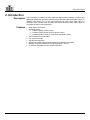
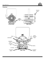
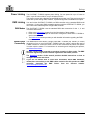
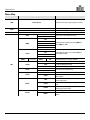
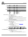
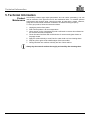
1
User Manual
Edition Notes
Edition Notes
The OVATION™ F-95WW User Manual Rev. 5 covers the description, safety
precautions, installation, programming, operation, and maintenance of the OVATION™
F-95WW. Chauvet released this edition of the OVATION™ F-95WW User Manual in
April 2015.
Trademarks CHAUVET® is a registered trademark of CHAUVET & Sons Inc. (d/b/a CHAUVET® or
Chauvet). The CHAUVET® logo in its entirety including the CHAUVET® name and the
dotted triangle, and all other trademarks in this manual pertaining to services, products,
or marketing statements are owned or licensed by Chauvet. Any other product names,
logos, brands, company names, and other trademarks featured or referred to within this
document are the property of their respective trademark holders.
Copyright Notice Chauvet owns the content of this User Manual in its entirety, including but not limited to
pictures, logos, trademarks, and resources.
© Copyright 2015 Chauvet. All rights reserved.
Electronically published by Chauvet in the United States of America.
Manual Use Chauvet authorizes its customers to download and print this manual for professional
information purposes only. Chauvet expressly prohibits the usage, copy, storage,
distribution, modification, or printing of this manual or its content for any other purpose
without written consent from Chauvet.
Document Printing For better results, print this document in color, on letter size paper (8.5 x 11 in), doublesided. If using A4 paper (210 x 297 mm), configure your printer to scale the content
accordingly.
Intended Audience Any person in charge of installing, operating, and/or maintaining this product should
completely read through the guide that shipped with the product, as well as this manual,
before installing, operating, or maintaining this product.
Disclaimer Chauvet believes that the information contained in this manual is accurate in all
respects. However, Chauvet assumes no responsibility for any errors or omissions in
this document. Chauvet reserves the right to revise and make changes to the content of
this document without obligation that Chauvet notify any person or company of such
revision or changes. This does not in any way constitute a commitment by Chauvet to
make such changes. Chauvet may issue a revision of this manual or a new edition to
incorporate such changes.
Document Revision The OVATION™ F-95WW User Manual Rev. 5 supersedes all previous versions of this
manual. Discard any older versions of this manual and replace with this version. Go to
www.chauvetprofessional.com for the latest version.
Author
Date
D. Couppe
4/1/15
OVATION™ F-95WW User Manual Rev. 5
Editor
M. Trouard
Date
4/9/15
Table of Contents
Table of Contents
1. Before You Begin ...................................................................................................................................... 1
What is Included ........................................................................................................................................................... 1
Claims .......................................................................................................................................................................................... 1
Manual Conventions .................................................................................................................................................................... 1
Symbols ....................................................................................................................................................................................... 1
Product at a Glance ...................................................................................................................................................... 1
Safety Notes ................................................................................................................................................................. 2
Personal Safety ............................................................................................................................................................................ 2
Mounting and Rigging .................................................................................................................................................................. 2
Power and Wiring ......................................................................................................................................................................... 2
Operation ..................................................................................................................................................................................... 2
Expected LED Lifespan ................................................................................................................................................ 2
2. Introduction ............................................................................................................................................... 3
Description .................................................................................................................................................................... 3
Features ........................................................................................................................................................................ 3
Overview ....................................................................................................................................................................... 4
Dimensions ................................................................................................................................................................... 5
3. Setup .......................................................................................................................................................... 6
AC Power ...................................................................................................................................................................... 6
AC Plug ........................................................................................................................................................................................ 6
Fuse Replacement ....................................................................................................................................................................... 6
..................................................................................................................................................................................................... 6
Power Linking ............................................................................................................................................................... 7
DMX Linking.................................................................................................................................................................. 7
DMX Modes ................................................................................................................................................................................. 7
Master/Slave Connectivity............................................................................................................................................................ 7
Mounting ....................................................................................................................................................................... 8
Orientation ................................................................................................................................................................................... 8
Rigging ......................................................................................................................................................................................... 8
4. Operation ................................................................................................................................................... 9
Control Panel Description ............................................................................................................................................. 9
Control Options ............................................................................................................................................................. 9
Programming ................................................................................................................................................................ 9
Menu Map ................................................................................................................................................................... 10
DMX Values ................................................................................................................................................................ 11
DMX Personality ........................................................................................................................................................................ 11
DMX Control............................................................................................................................................................................... 11
Loss of Signal Setting ................................................................................................................................................................ 11
Dimmer - Menu Control .............................................................................................................................................................. 12
Dimmer - Manual Control ........................................................................................................................................................... 12
Dimmer Speeds ......................................................................................................................................................................... 12
Dimmer Curves .......................................................................................................................................................................... 12
Control Panel Lock ..................................................................................................................................................................... 12
Passcode ................................................................................................................................................................................... 12
Menu Access Lock ..................................................................................................................................................................... 12
Reset.......................................................................................................................................................................................... 13
Performance Power Output Options .......................................................................................................................................... 13
Manual Zoom Control................................................................................................................................................................. 13
Master/Slave Mode .................................................................................................................................................................... 13
OVATION™ F-95WW User Manual Rev. 5
-i-
Table of Contents
5. Technical Information ............................................................................................................................. 14
Product Maintenance .................................................................................................................................................. 14
Technical Specifications ............................................................................................................................................. 15
Returns ....................................................................................................................................................................... 16
Contact Us ................................................................................................................................................... 16
-ii-
OVATION™ F-95WW User Manual Rev. 5
Before You Begin
1. Before You Begin
What is Included
Claims
· OVATION™ F-95WW
· Neutrik® powerCON® power cord
· Gel Frame (6.25 in/159 mm accessories)
· Warranty Card
· Quick Reference Guide
Carefully unpack the product immediately and check the box to make sure all the parts
are in the package and are in good condition.
If the box or the contents (the product and included accessories) appear damaged from
shipping or show signs of mishandling, notify the carrier immediately, not Chauvet.
Failure to report damage to the carrier immediately may invalidate your claim. In
addition, keep the box and contents for inspection.
For other issues, such as missing components or parts, damage not related to shipping,
or concealed damage, file a claim with Chauvet within 7 days of delivery.
Manual Conventions
Convention
1–512
50/60
<SET>
Settings
MENU>Settings
1–10
Yes/No
ON
Symbols
Meaning
A range of values in the text
A set of mutually exclusive values in the text
A button on the product’s control panel
A product function or a menu option
A sequence of menu options
A range of menu values from which to choose in a menu
A set of two mutually exclusive menu options in a menu
A unique value to be entered or selected in a menu
Symbols
Meaning
Critical installation, configuration, or operation information.
Failure to comply with this information may cause the product not
to work, damage third-party equipment, or cause harm to the
operator.
Important installation or configuration information. Failure to
comply with this information may keep the product from working.
Useful information.
The term “DMX” used throughout this manual refers to the USITT DMX512-A
digital data transmission protocol.
Product at a Glance
Use on Dimmer
Outdoor Use
Sound-Active
DMX
Master/Slave
OVATION™ F-95WW User Manual Rev. 5
x
x
x
P
P
Auto Programs
Auto-Ranging Power
Supply
Replaceable Fuse
User-Serviceable
Duty Cycle
x
P
P
x
x
-1-
Before You Begin
Safety Notes
Personal Safety
Mounting and
Rigging
Read all the following Safety Notes before working with this product. These notes
include important information about the installation, usage, and maintenance of this
product.
This product contains no user-serviceable parts. Any reference to servicing in
this User Manual will only apply to properly trained Chauvet certified
technicians. Do not open the housing or attempt any repairs.
All applicable local codes and regulations apply to proper installation of this
product.
·
·
·
·
·
·
·
·
·
Power and Wiring
·
Operation
·
·
·
·
·
·
·
Avoid direct eye exposure to the light source while the product is on.
Always disconnect this product from its power source before servicing.
Always connect this product to a grounded circuit to avoid the risk of electrocution.
Do not touch this product’s housing during operation because it may be very hot.
This product is for indoor use only! (IP20) To prevent risk of fire or shock, do not
expose this product to rain or moisture.
CAUTION: When transferring product from extreme temperature environments,
(e.g. cold truck to warm humid ballroom) condensation may form on the internal
electronics of the product. To avoid causing a failure, allow product to fully
acclimate to the surrounding environment before connecting it to power.
Mount this product in a location with adequate ventilation, at least 20 in (50 cm)
from adjacent surfaces.
Make sure there are no flammable materials close to this product while it is
operating.
When hanging this product, always secure to a fastening device using a safety
cable.
Always make sure you are connecting this product to the proper voltage in
accordance with the specifications in this manual or on the product’s specification
label.
Never connect this product to a dimmer pack or rheostat.
Never disconnect this product by pulling or tugging on the power cable.
Do not operate this product if you see damage on the housing, lenses, or cables.
Have the damaged parts replaced by an authorized technician at once.
To eliminate unnecessary wear and improve its lifespan, during periods of non-use
completely disconnect the product from power via breaker or by unplugging it.
Do not cover the ventilation slots when operating to avoid internal overheating.
The maximum ambient temperature is 113 °F (45 °C). Do not operate this product
at a higher temperature.
In case of a serious operating problem, stop using this product immediately!
In the unlikely event that your Chauvet product may require service, contact
Chauvet Technical Support.
Expected LED
Lifespan
-2-
LEDs gradually decline in brightness over time, mostly because of heat. Packaged in
clusters, LEDs exhibit higher operating temperatures than in ideal, single-LED
conditions. For this reason, using clustered LEDs at their fullest intensity significantly
reduces the LEDs’ lifespan. Under normal conditions, this lifespan can be 90,000 to
100,000 hours. If extending this lifespan is vital, lower the operating temperature by
improving the ventilation around the product and reducing the ambient temperature to
an optimal operating range. In addition, limiting the overall projection intensity may also
help to extend the LEDs’ lifespan.
OVATION™ F-95WW User Manual Rev. 5
Introduction
2. Introduction
Description
Features
The OVATION™ F-95WW is a warm white LED wash product featuring a compact and
lightweight design that delivers a beautiful soft flat field with high-quality glass optics. Its
massive zoom range of 21° to 83° and beautifully soft, warm white wash make it a
versatile Fresnel. Virtually quiet operation and smooth dimming control make it ideal for
any theatrical and/or studio application.
· Warm white LED Fresnel
· Operating modes:
· 1-channel (UNO): dimmer control
· 2-channel (DOS): dimmer and fine dimmer control
· 3-channel (STD.P): dimmer, fine dimmer, and strobe control
· 16-bit dimming for smooth fades
· Flat, even field of light
· Virtually silent operation
· Simple and complex DMX channel profiles for programming versatility
· Manually controlled variable zoom angle between 21° and 83°
· 3- and 5-pin XLR data input and output connectors
OVATION™ F-95WW User Manual Rev. 5
-3-
Introduction
Overview
Gel Frame
Holder
Zoom
Adjustment
Knobs
Front View
Side View
Dimmer
Adjustment
Knob
Handle
Menu Buttons
powerCON®
Output
powerCON®
Input
Display
Fuse Holder
3- and 5-pin
DMX In
-4-
Rear View
3- and 5-pin
DMX Out
OVATION™ F-95WW User Manual Rev. 5
Introduction
Dimensions
11 in
279 mm
15.2 in
389 mm
12.8 in
325 mm
OVATION™ F-95WW User Manual Rev. 5
-5-
Setup
3. Setup
Each OVATION™ F-95WW has an auto-ranging power supply that works with an input
voltage range of 100~240 VAC, 50/60 Hz. To determine the power requirements for
each OVATION™ F-95WW, refer to the label affixed to the product. You can also refer
to the Technical Specifications chart in this manual.
The listed current rating indicates the maximum current draw during normal operation.
For more information, you may download Sizing Circuit Breakers from the Chauvet
website www.chauvetprofessional.com.
AC Power
·
·
Always connect this product to a protected circuit with an appropriate electrical
ground to avoid the risk of electrocution or fire.
To eliminate unnecessary wear and improve its lifespan, during periods of nonuse completely disconnect the product from power via breaker or by
unplugging it.
Never connect this product to a rheostat (variable resistor) or dimmer circuit, even
if the rheostat or dimmer channel serves only as a 0 to 100% switch.
AC Plug The OVATION™ F-95WW comes with a power input cord terminated with a Neutrik®
powerCON® A connector on one end and an Edison plug on the other end (U.S. market).
If the power input cord that came with your product has no plug, or if you need to change
the Edison plug, use the table below to wire the new plug to the power input cord.
Connection
Wire (U.S.)
Wire (Europe)
Screw Color
AC Live
AC Neutral
AC Ground
Black
White
Green/Yellow
Brown
Blue
Green/Yellow
Yellow or Brass
Silver
Green
Fuse Replacement
Make sure to disconnect the product’s power cord before replacing a blown fuse.
1. Disconnect this product from power.
2. Using a Phillips #2 head screwdriver, unscrew the fuse holder
cap from the housing.
3. Remove the blown fuse and replace with another fuse of the
same type and rating (T 3.15 A, 250 V).
4. Screw the fuse holder cap back in place and reconnect power.
Always replace the blown fuse with another of the same type and rating.
-6-
OVATION™ F-95WW User Manual Rev. 5
Setup
Power Linking
The OVATION™ F-95WW supports power linking. You can power link up to 15 units on
120 V; up to 25 units on 208 V; or up to 28 units on 230 V.
This product comes with a Neutrik® powerCON® input power cord. This product does not
come with a power linking cable; however, a power linking cable is available as an option.
DMX Linking
You can link the OVATION™ F-95WW to a DMX controller using a standard DMX serial
connection. If using other DMX-compatible products with the OVATION™ F-95WW, you
can control each individually with a single DMX controller.
DMX Modes The OVATION™ F-95WW uses the standard DMX data connection for the 1-, 2- and
Master/Slave
Connectivity
3-channel DMX modes.
· Refer to the Introduction chapter for a brief description of these modes.
· Refer to the Operation chapter to learn how to configure the OVATION™ F-95WW to
work in these modes.
· The DMX Values section provides you with detailed information regarding the DMX
modes.
The Master/Slave mode allows a single OVATION™ F-95WW (the “master”) to control
the actions of one or more OVATION™ F-95WW units (the “slaves”) without the need of
a DMX controller to control the slaves. Once set and connected, the slaves will operate
in unison with the master. For instructions on connecting and configuring this product,
see Master/Slave Mode.
DO NOT connect a DMX controller to products operating in Slave mode. The DMX
controller signals may interfere with the signals from the master product.
The Operation section of this manual provides detailed instructions on how to
configure the master and slaves.
If you are not familiar with or need more information about DMX standards,
master/slave connectivity, or the DMX cables needed to link this product to a DMX
controller, download the DMX Primer from the Chauvet website:
www.chauvetprofessional.com.
OVATION™ F-95WW User Manual Rev. 5
-7-
Setup
Mounting
Before mounting this product, read and follow the Safety Notes. For our CHAUVET®
Professional line of mounting clamps, go to http://trusst.com/products/.
Orientation Always mount this product in a safe position. The OVATION™ F-95WW may be
mounted in any position; however, make sure there is adequate room for ventilation,
configuration, and maintenance.
Rigging Chauvet recommends using the following general guidelines when mounting this
product.
Procedure
· When selecting an installation location, consider easy access to this product for
operation, programming adjustments, and routine maintenance.
· Make sure to mount this product away from any flammable material as indicated in
the Safety Notes.
· Never mount in places where rain, high humidity, extreme temperature changes, or
restricted ventilation may affect the product.
· If hanging this product, make sure that the mounting location can support the
product’s weight. See the Technical Specifications for the weight-bearing
requirements of this product.
· When hanging this product, always secure to a fastening device using a safety cable.
The OVATION™ F-95WW comes with a hanging/mounting bracket to which you can
attach mounting clamps. The bracket has 13-mm holes, which are appropriate for this
purpose. You must supply your own mounting clamps, so be sure the clamps are
capable of supporting the weight of this product. Use at least one mounting point per
product where necessary.
Safety Cable
Mounting Clamp
Hanging/Mounting
Bracket
Secure the safety
cable using the
passageway on
the side of the
product
Mounting Diagram
Overhead Mounting
Bracket
Adjustment
Hand Shank
Floor Mounting
-8-
OVATION™ F-95WW User Manual Rev. 5
Operation
4. Operation
Control Panel
Description
Button
Function
<MENU>
<ENTER>
Exits from the current menu or function
Activates the currently displayed menu option or sets the
selected value in the current function
Scrolls up the list of menu options or increases the numeric value
when in a function
Scrolls down the list of menu options or decreases the numeric
value when in a function
<UP>
<DOWN>
Control Options
You can set the starting address of the OVATION™ F-95WW in the 001–512 DMX
range. This enables control of up to 170 products in the 3-channel STD.P personality.
Programming
Refer to the Menu Map for a description of your programming options. The menu map
shows the main level and a variable number of programming levels for each option.
· Press <MENU> repeatedly to go to the desired main level. Press <ENTER> to select
the main level and go to the first programming level for that option.
· Press <UP> or <DOWN> to scroll through the options or values within the current
programming level. When the desired option shows on the display, press <ENTER>
to select the option. If there are deeper programming levels, those options will show
on the display.
· Press <MENU> repeatedly to exit to the previous level.
OVATION™ F-95WW User Manual Rev. 5
-9-
Operation
Menu Map
Main Level
Programming Levels
DIM
D.000–D.100
RUN
ADDR
Description
Selects the amount of light output (0–100%)
DMX
Receives DMX signals from the DMX controller
SLAV
Receives DMX signals from the master
D.001–D.512
Sets the DMX starting address
OFF
KEY
Sets to key lock (passcode mode)
ON
OFF
DIM1
DIMX
Selects dimmer speeds from fast (DIM1) to
slow (DIM4) or OFF
DIM2
DIM3
DIM4
OFF
CV1
CURV
Selects dimmer curves from small (CV1) to
large (CV3) or OFF
CV2
CV3
REST
SET
****
(Enter Passcode)
PERS
SLCK
DERR
PERF
MCON
-10-
REST
OK
Resets the fixture to factory defaults
UNO
1-channel DMX personality
DOS
2-channel DMX personality
STD.P
3-channel DMX personality
OFF
ON
Sets menu-level access lock
BLAK
Blacks out fixture upon loss of DMX signals
SAVE
Continues with last command upon loss of
DMX signals
LIVE
Maintains LED cooling by balancing fan and
power output level
STDO
Maintains LED cooling by limiting power output
level
POWR
Maintains LED cooling by using fan and
allowing full power output
SELF
No DMX signals are sent through DMX output
MAST
Sends DMX signals to OVATION™ F-95WW
slaves
OVATION™ F-95WW User Manual Rev. 5
Operation
DMX Values
UNO Channel
1
DOS Channel
1
2
STD.P Channel
Function
Dimmer
Function
Dimmer
Dimmer Fine
Function
1
2
Dimmer
Dimmer Fine
3
Strobe
Value
Percent/Setting
000 ó 255 0–100%
Value
Percent/Setting
000 ó 255 0–100%
000 ó 255 0–100%
Value
000 ó 255
000 ó 255
000 ó 009
010 ó 099
100 ó 109
110 ó 179
180 ó 189
190 ó 255
Percent/Setting
0–100%
0–100%
No function
Strobe (slow to fast)
No function
Lighting effect
No function
Random strobe
DMX Personality Set the DMX personality as follows.
1. Go to the SET main level.
2. Select the PERS programming level.
3. Select the desired personality: UNO (1-channel), DOS (2-channel),
or STD.P (3-channel).
DMX Control
· See the DMX Control section for the highest starting address you can select for
each personality.
· Make sure that the starting addresses on the various products do not overlap
due to the new personality setting.
DMX Control allows you to assign each product to a unique starting address on the DMX
controller. All products with the same starting address will respond in unison.
1. Select a DMX personality.
2. Set the running mode:
· Go to the RUN main level.
· Select DMX.
Note: For information on the SLAV option, see Master/Slave Mode.
3. Set the starting address:
· Go to the ADDR main level.
· Select the starting address D.001–D.512.
The highest recommended starting address for each DMX mode is as follows:
Loss of Signal Setting
DMX
DMX
DMX
DMX
DMX
DMX
Mode
Address
Mode
Address
Mode
Address
UNO
DOS
STD.P
512
511
510
This setting controls how the product responds when the DMX signal is lost.
1. Go to the SET main level.
2. Select the DERR programming level.
· Select BLAK to turn off the LEDs when the signal is lost.
· Select SAVE to use the last command programmed when the signal is lost.
OVATION™ F-95WW User Manual Rev. 5
-11-
Operation
Dimmer - Menu To adjust the light output of the OVATION™ F-95WW, select the dimmer setting as
Control follows.
1. Go to the DIM main level.
2. Select the desired dimmer setting D.000–D.100 (0–100% light output).
Dimmer - Manual Manually adjust the light output by using the dimmer adjustment knob, as follows.
Control 1. Press the dimmer adjustment knob above the display twice.
2. Select the desired dimmer setting D.000–D.100 (0–100% light output) by turning the
knob clockwise (value increases) or counter-clockwise (value decreases).
·
Dimmer Speeds
When using the dimmer adjustment knob, the lowest dimmer value stops at D.000
and the highest dimmer value stops at D.100.
· During manual dimmer control, you can also use <UP> or <DOWN>, which will
cycle through all the dimmer values.
· After 30 seconds of dimmer adjustment knob inactivity, M. appears on the display.
Select the dimmer speed of the OVATION™ F-95WW by selecting the DIMX
programming level.
1. Go to the SET main level.
2. Select the DIMX programming level.
3. Select a dimmer speed DIM1–DIM4 (fast to slow) or OFF (linear output).
When selecting DIM1–DIM4, the output will correspond to the dimmer curve option
selected under the dimmer curves programming level (CURV).
Dimmer Curves Select the dimmer curve of the OVATION™ F-95WW by selecting the CURV
programming level. These options simulate the dimmer curve of an incandescent lighting
product.
1. Go to the SET main level.
2. Select the CURV programming level.
3. Select a dimmer curve CV1–CV3 (small to large) or OFF (linear output).
Control Panel Lock This setting enables you to activate or deactivate the control panel lock, which keeps
non-authorized personnel from changing the product’s settings.
1. Go to the KEY main level.
2. Select either ON (activate) or OFF (deactivate).
When the control panel lock is activated, after 30 seconds of control panel inactivity
or after turning on the product, the product will prompt you to enter the passcode.
Passcode After being prompted to enter the passcode:
·
Press <UP>, <DOWN>, <UP>, <DOWN>, <ENTER>.
Note: Asterisks (*) appear on the display when entering the passcode.
Menu Access Lock This setting enables you to activate or deactivate the menu access lock. Activating the
menu access lock prevents non-authorized personnel from making any changes to the
programming levels under the SET main level.
1. Go to the SET main level.
2. Go to the SLCK programming level.
3. Select either ON (activate) or OFF (deactivate).
When the menu access lock is activated, in order to access the SET programming
levels, the product will prompt you to enter the passcode. Enter the passcode as
described in Passcode.
-12-
OVATION™ F-95WW User Manual Rev. 5
Operation
Reset To reset the OVATION™ F-95WW to the factory default settings, follow the instructions
below.
1. Go to the SET main level.
2. Select the REST programming level and then the display becomes blank.
Enter the passcode as described in Passcode. After successfully entering the
passcode, REST blinks on the display during the reset process.
3. OK appears on the display when finished.
Performance Power The OVATION™ F-95WW offers three power output options during the cooling of the
Output Options fixture’s LEDs.
1. Go to the SET main level.
2. Select the PERF programming level.
3. Select from the following options:
· Select LIVE to cool the LEDs by balancing the use of the fan and the power
output level.
· Select STDO to cool the LEDs by maintaining the use of the fan and limiting the
power output level.
· Select POWR to cool the LEDs by maintaining the use of the fan and allowing
full power output.
Manual Zoom Control The OVATION™ F-95WW has a 21° to 83° manually controlled zoom range. Adjust the
zoom angle as follows.
· Locate the zoom adjustment knobs on either side of the OVATION™ F-95WW and
turn the knobs to increase or decrease the zoom angle.
Master/Slave Mode The Master/Slave mode allows a single OVATION™ F-95WW (the “master”) to control
the actions of one or more OVATION™ F-95WW units (the “slaves”) without the need of
a DMX controller to control the slaves. The master will be set to operate in Master mode
(MAST), while the slaves will be set to operate in Slave mode (SLAV). Once set and
connected, the slaves will operate in unison with the master.
Configure the units as indicated below.
The Slaves:
1.
2.
3.
4.
Go to the RUN main level.
Select SLAV.
Connect the DMX input of the first slave to the DMX output of the master.
Connect the DMX input of the subsequent slaves to the DMX output of the previous
slave.
Finish setting and connecting all the slaves.
5.
The Master:
1.
2.
3.
4.
5.
Go to the SET main level.
Select the MCON programming level.
Select MAST.
Note: If you select SELF, no DMX signals are sent to the slaves.
Make the master the first product in the DMX daisy chain.
Control the master using the DMX controller and the slaves will operate in unison.
Do not connect a DMX controller to the products configured for slave operation.
The DMX controller may interfere with signals from the master.
OVATION™ F-95WW User Manual Rev. 5
-13-
Technical Information
5. Technical Information
Product
Maintenance
Dust build-up reduces light output performance and can cause overheating. This can
lead to reduction of the light source’s life and mechanical wear. To maintain optimum
performance and minimize wear, clean this product at least twice a month. However,
usage and environmental conditions contribute to increased cleaning frequency.
To clean your product, follow the instructions below.
1. Unplug the product from power.
2. Wait until the product is at room temperature.
3. Use a vacuum (or dry compressed air) and a soft brush to remove dust collected on
the external vents and components.
4. Clean all external surfaces with a mild solution of non-ammonia glass cleaner or
isopropyl alcohol.
5. Apply the solution directly to a soft, lint-free cotton cloth or a lens cleaning tissue.
6. Wipe any dirt or grime to the outside edges of the lens surface.
7. Gently polish the lens surfaces until they are free of haze and lint.
Always dry the external surfaces thoroughly and carefully after cleaning them.
-14-
OVATION™ F-95WW User Manual Rev. 5
Technical Specification
Technical Specifications
Dimensions and
Weight
Length
Width
Height
Weight
12.8 in (325 mm)
11 in (279 mm)
15.2 in (389 mm)
13.4 lb (6.1 kg)
Note: Dimensions in inches rounded to the nearest decimal digit.
Power
Power Supply Type
Range
Voltage Selection
Switching (internal)
100 to 240 VAC, 50/60 Hz
Auto-ranging
Parameter
120 V, 60 Hz
230 V, 50 Hz
Consumption
Operating current
Power linking current (units)
Fuse
108 W
0.89 A
13.6 A (15 units)
T 3.15 A, 250 V
110 W
0.48 A
13.6 A (28 units)
T 3.15 A, 250 V
Power I/O
U.S./Worldwide
Europe
Power input connector
Power output connector
Power cord plug
Neutrik® powerCON® A
Neutrik® powerCON® B
Edison (U.S.)
Neutrik® powerCON® A
Neutrik® powerCON® B
Local plug
Type
Power
Lifespan
LED
10 W
100,000 hours
Color
Quantity
Current
Warm White
9
2.8 A
Light Source
Photo Optic
Thermal
Parameter
Illuminance @ 5 m (11°)
Illuminance @ 5 m (60°)
Beam angle
Field angle
Zoom angle
1,430 lx
133 lx
11° to 60°
21° to 83°
21° to 83°
Max. External Temperature
Cooling System
113 °F (45 °C)
Fan-Assisted Convection
I/O Connectors
Connector Type
Channel Range
3- and 5-pin XLR
Sockets
1, 2 or 3
Product Name
Item Code
UPC Number
OVATION™ F-95WW
01030721
781462210694
DMX
Ordering
OVATION™ F-95WW User Manual Rev. 5
-15-
User Manual
Returns
You must send the product prepaid, in the original box, and with the original packing and
accessories. Chauvet will not issue call tags.
Call Chauvet and request a Return Merchandise Authorization (RMA) number before
shipping the product. Be prepared to provide the model number, serial number, and a
brief description of the cause(s) for the return.
Clearly label the package with an RMA number. Chauvet will refuse any product
returned without an RMA number.
DO NOT write the RMA number directly on the box. Instead, write it on a properly
affixed label.
Once you have received the RMA number, include the following information on a piece
of paper inside the box:
· Your name
· Your address
· Your phone number
· RMA number
· A brief description of the problem(s)
Be sure to pack the product properly. Any shipping damage resulting from inadequate
packaging will be the customer’s responsibility. FedEx packing or double-boxing is
recommended.
Chauvet reserves the right to use its own discretion to repair or replace returned
product(s).
Contact Us
WORLD HEADQUARTERS - Chauvet
General Information
Technical Support
Address: 5200 NW 108th Avenue
Voice: (954) 577-4455 (Press 4)
Sunrise, FL 33351
Fax:
(954) 756-8015
Voice:
(954) 577-4455
Email: [email protected]
Fax:
(954) 929-5560
World Wide Web www.chauvetlighting.com
Toll free: (800) 762-1084
UNITED KINGDOM AND IRELAND - Chauvet Europe Ltd.
General Information
Technical Support
Address: Unit 1C
Email: [email protected]
Brookhill Road Industrial Estate
World Wide Web www.chauvetlighting.co.uk
Pinxton, Nottingham, UK
NG16 6NT
Voice:
+44 (0)1773 511115
Fax:
+44 (0)1773 511110
MEXICO - Chauvet Mexico
General Information
Technical Support
Address: Av. Santa Ana 30
Email: [email protected]
Parque Industrial Lerma
World Wide Web www.chauvet.com.mx
Lerma, Mexico C.P. 52000
Voice:
+52 (728) 285-5000
CHAUVET EUROPE - Chauvet Europe BVBA
General Information
Technical Support
Address: Stokstraat 18
Email: [email protected]
9770 Kruishoutem
World Wide Web www.chauvetlighting.eu
Belgium
Voice:
+32 9 388 93 97
Outside the U.S., United Kingdom, Ireland, Mexico, or Benelux contact the dealer of record.
Follow their instructions to request support or to return a product. Visit our website for contact
details.
OVATION™ F-95WW User Manual Rev. 5