1
)$9,3
9LVWD,QWHUDFWLYH3KRQH0RGXOH
,QVWDOODWLRQDQG6HWXS*XLGH
N6431-1 11/99
Table of Contents
• • • • • • • • • • • • • • • • • • • • • • • • • • • • • • • • • • • • • • • • • •
Section 1. GENERAL DESCRIPTION ................................................................................1-1
Application and Description..............................................................................1-1
Control Panels Supported .................................................................................1-2
Differences between the FA4285 and FA4286 VIP Module ............................1-2
FA4286 VIP Module Specifications ..................................................................1-3
Section 2. MOUNTING AND WIRING.................................................................................2-1
Mounting the FA4286 VIP Module (all Controls)............................................2-1
Wiring Connections ...........................................................................................2-2
Speaker Connections (Optional) and Volume Control ....................................2-2
Special Wiring Notes .........................................................................................2-3
Section 3. PROGRAMMING ...............................................................................................3-1
Programming the Control for FA4286 VIP Module Usage .............................3-1
Entering the FA4286 VIP Module Programming Mode ..................................3-2
Programming Notes...........................................................................................3-2
Programming Zone Descriptors ........................................................................3-4
Systems with Alpha Keypads............................................................................3-5
Systems Using Only Fixed-Word Keypads ......................................................3-5
Programming Note ............................................................................................3-6
Programming Relay Voice Descriptors.............................................................3-7
Programming Speaker Output Mode ...............................................................3-9
Voice Menu for Programming Speaker Output Mode .....................................3-9
Section 4. BASIC OPERATING GUIDE ..................................................................................... 4-1
Phone Code.........................................................................................................4-1
Setting the Phone Code .....................................................................................4-1
Phone Access When On-Premises.....................................................................4-2
Phone Access When Off-Premises.....................................................................4-2
Performing System Commands ........................................................................4-3
Confirmation Sounds and Voice Announcements After Command Entries ..4-4
Turning Remote Phone Access On and Off ......................................................4-4
Installations Where the Telephone System
Includes an Answering Machine.....................................................................4-5
i
Table of Contents (cont'd)
End User Relay Command Mode When Using the FA4286 VIP Module.......4-6
Using the Phone Panic Feature ........................................................................4-7
Using the Novice Voice Menu ...........................................................................4-7
About the Speaker Output ................................................................................4-8
Section 5. TROUBLESHOOTING ............................................................................................... 5-1
Typical System Problems and Solutions ..........................................................5-1
Section 6. APPENDICES............................................................................................................. A-1
In the Event of Trouble with Regular Telephone Service .............................. A-1
FCC Statement, Part 15 .................................................................................. A-2
FCC Statement, Part 68 ................................................................................... A-2
TELCO-Provided Coin Service Advisement.................................................... A-3
TABLES:
Table 2-1. Wiring Connections .........................................................................2-3
Table 3-1. FA4286 Zone Descriptor Vocabulary List ......................................3-6
Table 3-2. Relay Voice Descriptors Vocabulary
and Custom Word Substitutes .............................................................3-8
Table 3-3. Speaker Control Categories ..........................................................3-10
DIAGRAMS
Summary of Connections ................................................................................... A-4
ii
S E C T I O N
1
General Description
• • • • • • • • • • • • • • • • • • • • • • • • • • • • • • • • • • • • • • • • • •
In This Section
♦ Application and Description
♦ Differences between the FA4285 and FA4286
♦ Control Panels Supported
VIP Module
♦ FA4286 VIP Module Specifications
• • • • • • • • • • • • • • • • • • • • • • • • • • • • • • • • • • • • • • • • • •
Application and Description
The First Alert Professional FA4286 VISTA Interactive Phone (VIP) Module
is an add-on accessory that can be used with certain First Alert Professional
controls* to provide an interactive phone capability to the security system.
This feature will permit access to the security system via any Touch-tone
phone (either on premises or by a call-in when away from the premises).
NOTE: Only one FA4286 VIP Module can be used in a system.
All controls that support a FA4285 Voice Module can support the FA4286 VIP
Module as well. Existing FA4285 Voice Module programming and downloading
fields for the control panel still apply.
When connected, the FA4286 VIP Module will enable the user to do the following via any Touch-tone telephone:
1. Receive synthesized voice messages over the phone regarding the
status of the security system.
2. Arm and disarm the security system and perform most other commands using the telephone keypad, with voice annunciation being
provided as confirmation after any command is entered.
3. Turn certain lights/appliances on and off via the telephone using the
Relay Command Mode. This capability is possible only with the
FA4286 VIP Module and with controls supporting the Relay Command Mode.
1-1
FA4286 VIP Module Installation and Setup Guide
If the system has relays, but does not support the Relay Command Mode, they
still can be controlled via the phone (in same way as from a wired keypad), but
no voice feedback will occur.
The on-premises phone system need not have Touch-tone service, but the
phone used for security system access must have Touch-tone capability.
Switchable phones should be set for Touch-tone temporarily before attempting phone access. However, an off-premises phone that does not have Touchtone service and uses pulses for dialing may not permit switching to Touchtone after dialing; in such a case, phone access from that phone will not be
possible.
Control Panels Supported
These following control panels require specific software revisions for use with
the FA4286 VIP Module:
FA142C Rev. 13 (micro. WA6764V10) or above; FA148C Rev.1 or above:
FA162C Rev. 7 (micro WA7840V6) or above; FA1220CV Rev. 15 or above;
FA1340C Rev. 5 or above; FA1600C/CA/CB Rev. 6 or above.
Differences between the FA4285 and FA4286 VIP Module
The FA4286 VIP Module offers increased capabilities when used with a control that supports the FA4285. These include:
•
Thermostat control (using 4500 thermostats). Temperature settings
can be adjusted and room temperature can be monitored from a touch
tone phone on or off the premises.
The 4500 thermostat cannot be used in UL installations.
®
1-2
•
Synthesized voice prompts to instruct the user on how to initiate
common user commands, such as arming or disarming the system,
relay and thermostat control, etc.
•
Panic alarms can be activated from a premises touch-tone phone.
•
Audio output capable of driving a loudspeaker, providing system
status, warnings, and confirmation of user commands
•
Telephone programming mode for FA4286 installation options.
Section 1. General Description
FA4286 VIP Module Specifications
Physical:
6-7/16” (163mm) W x 4-1/4” 108mm)
H x 1-1/4” (32mm) D.
Electrical:
Input voltage: 12VDC (from control)
Current Usage:
300 mA; 220 mA if the warning
speaker is not used
Device Address:
Factory set to address 4, not
changeable
FCC Registration No.:
AC3USA-74659-KX-N
Ringer Equivalence:
1.0 B
The FA4286 VIP Module complies with FCC RULES, Parts 15 & 68.
1-3
FA4286 VIP Module Installation and Setup Guide
1-4
S E C T I O N
2
Mounting and Wiring
• • • • • • • • • • • • • • • • • • • • • • • • • • • • • • • • • • • • • • • • • •
In This Section
♦ Mounting the FA4286 VIP Module
♦ Wiring Connections
♦ Speaker Connections and Volume Control
♦ Caller ID Units
• • • • • • • • • • • • • • • • • • • • • • • • • • • • • • • • • • • • • • • • • •
Mounting the FA4286 VIP Module (All Controls)
•
Mount the FA4286 VIP Module in the control cabinet if space is available,
or on the side of the cabinet or adjacent to it. Pry off the FA4286’s cover
prior to wiring.
•
If mounted inside the cabinet with the control, use double-sided adhesive
tape to attach the Module to the interior surface of the cabinet, or hang
on two screws. Do not mount on the cabinet door or attempt to attach it to the PC board. The FA4286's cover can be left off if the Module is mounted within the cabinet.
•
To mount the FA4286 outside the cabinet, use the screw holes at the rear
of the Module, which can be mounted horizontally or vertically (doublesided adhesive tape may be used in place of screws, if preferred). Wires
can be brought out from the side or back (use the round breakout on the
back). When the FA4286’s wiring is completed (as shown below), replace
the Module's cover (with label affixed, as indicated next).
•
Affix the supplied connections label to the inside of the FA4286's cover if
the cover is to be used. Otherwise, affix the label to the inside of the control cabinet's door.
2-1
FA4286 VIP Module Installation and Setup Guide
Wiring Connections
1. Make 12V (+), Ground (–), Data in, and Data out connections from the
FA4286 VIP Module to the keypad terminals on the control Using the
connector cable supplied and referring to Summary of Connections located on the inside back cover, wire as follows:
Color Lead
Terminal On Control
GREEN
to
DATA IN
BLACK
to
AUX GROUND (–)
RED
to
AUX +
YELLOW
to
DATA OUT
2. Insert the keyed connector at the other end of the above leads into the
mating header on the FA4286. Refer to Summary of Connections.
3. Connect terminals 1 through 5 on the FA4286 as indicated in Figure 1
and Table 2-1. Use an RJ31X jack (CA38A in Canada) with a directconnect cord and make all connections exactly as shown. If the leads on
the direct-connect cord are too short to reach their assigned terminals,
splice additional wires to them, as required.
Some controls may require different wiring connections than those indicated in
Table 2-1 and shown in Summary of Connections located on back inside cover
depending on whether other devices that connect to the telephone lines are also
being used (for example, an Audio Alarm Verification unit). Refer to the FA4286
VIP Module section in the control’s installation and setup guide for information on
any wiring variations that might be necessary.
Speaker Connections (optional) and Volume Control
2-2
•
Single Speaker: Connect an Ademco 746 Indoor Speaker or any other 8ohm speaker between speaker terminals 6 and 7 on the FA4286 as shown
in Summary of Connections. Do not use a single 4-ohm speaker in
this setup. If you only have 4-ohm speakers, you must connect two of
them in series.
•
Dual Speakers: Connect the speakers in series between the FA4286
VIP Module speaker terminals 6 and 7. Note that there will be a decrease
in volume from each of two 8-ohm speakers in series as compared to when
only a single 8-ohm speaker is connected. The same is true if two 4-ohm
speakers in series are used in this setup.
•
Speaker Volume Control: The speaker volume control is located near
the transformer on the FA4286 board. Refer to Summary of Connections.
Section 2. Mounting and Wiring
Note that this control does not adjust the volume of the output from the
FA4286 to the phone handset.
Do NOT connect speakers in parallel.
Do NOT use a single 4-ohm speaker.
Damage to the FA4286 may result.
Special Wiring Notes:
1. Wire the FA4286 VIP Module exactly as indicated in Table 2-1 and on the
Summary of Connections diagram on the inside back cover of this guide,
unless the control’s installation and setup guide indicate otherwise (due,
for example, to the use of other phone-connected devices such as an Audio
Alarm Verification unit).
2. You MUST make a connection to the incoming Telco line via an RJ31X
jack (CA38A in Canada) and direct-connect cord, as shown in the Summary of Connections diagram, even if the system is not connected to a
central station. The FA4286 will not operate properly if this is not
done.
3. If Touch-tones are not present following access to the security system via
an on-premises phone, try reversing the pair of wires connected to terminals 3 & 4 on the FA4286 VIP Module, and the pair of wires connected to
the "Handset" TIP & RING terminals on the control.
4. Connect a Caller ID unit to the security system as you would an answering machine and other phones.
Table 2-1. Wiring Connections
FA4286 VIP Module Terminal
Connects to:
Phone In (Tip)
“Handset” TIP terminal on control
Phone In (Ring)
“Handset” RING terminal on control
Phone Out (Tip)
BROWN lead from direct-connect cord
Phone Out (Ring)
GRAY lead from direct-connect cord
Not Connected
Not Connected
Audio Out
One side of speaker
Audio Out
One side of speaker
2-3
FA4286 VIP Module Installation and Setup Guide
2-4
S E C T I O N
3
Programming
• • • • • • • • • • • • • • • • • • • • • • • • • • • • • • • • • • • • • • • • • •
In This Section
♦ Programming the Control for FA4286 VIP
Module Usage
♦ Entering the FA4286 VIP Module Programming Mode
♦ Programming Zone Descriptors
♦ Systems with Alpha Keypads
♦ Systems Using Only Fixed-Word Keypads
♦ Programming Note
♦ Programming Relay Voice Descriptors
♦ Programming Speaker Output Mode
♦ Voice Menu for Programming Speaker
Output Mode
• • • • • • • • • • • • • • • • • • • • • • • • • • • • • • • • • • • • • • • • • •
The programming steps that follow must be completed within 3 hours of powering up the FA4286. This time constraint is necessary to prevent accidental end
user access to the programming capability of the Module. In the event that this
time period elapses, it will be necessary to remove and then re-apply primary
power to the module as indicated in the information that follows the end of programming on page 3-4.
Programming The Control For FA4286 VIP Module Usage
It is important that all fields related to the operation of the FA4286 be properly programmed. These include entries for selection of the 2-digit phone
code, ring detection count, and, in some cases, entries for FA4285/FA4286 supervision. Refer to the control's programming section for inclusion of the
FA4285/FA4286 supervision codes.
The FA4286 VIP Module is factory set to device address 4. For addressable
controls a Device Address of 04 must be programmed in Device Programming
Mode at the control panel. If using a speaker, assign the FA4286 to the same
partition to which the monitored keypad (programmed in field 00 of FA4286 program mode) is assigned.
3-1
FA4286 VIP Module Installation and Setup Guide
Entering the FA4286 VIP Module Programming Mode:
1. Pick up a premises touch tone phone connected to the FA4286 handset
output. Programming cannot be done from an off-premises phone.
2. Enter the 2-digit phone code on the phone keypad (such as “7” followed by
“✴” and after hearing status announcement, press # 98. Do not press
keys while the FA4286 is announcing. The FA4286 will establish a
phone connection and announce the contents of programming field 00.
Programming Notes
•
New data may be entered into each field once the field contents are announced. Once accepted, the new data will be echoed back by synthesized
voice announcement. If an erroneous entry is detected, a buzzer sound
will be heard in the phone receiver, and the current field and data will be
repeated. If you wish to change the data again, it can be re-entered after
the echoed voice announcement.
•
You must wait for an echoed announcement and if satisfied with a field
entry, press “✴” to go on to the next field. If you want to go back one
field, press “ # .”
•
If you do not need to program all fields, such as to modify a program already entered, press “✴” on the phone keypad to advance by one field until desired field number is announced. For example, pressing “✴”
+“✴”will advance the field from 00 to 02.
•
Once all fields have been programmed as required and accurately echoed
back, you can hang up the phone.
•
If necessary, you will have 15 minutes to re-enter programming mode.
The 15 minute limit is to prevent the user from accidentally entering programming mode. If more than 15 minutes have elapsed, it will be necessary to remove the 12 volt power temporarily from the FA4286 by
disconnecting the keyed header that connects it to the control panel (located near the 2 relays). Wait 5 seconds before replacing the header to
restore power then re-enter programming mode as outlined in this section.
System default settings are indicated by [default] following an entry.
3-2
Section 3. Programming
•
Field 00: Monitored Keypad Address
This field enables or disables the 4500 thermostat AND speaker output features and selects which keypad to monitor.
In a system that uses addressable keypads:
Select the keypad whose status the FA4286 will monitor to control the
4500 thermostat and/or trigger speaker messages, and set its device address (01 to 31) in this field. The selected keypad should be assigned to
the partition where the 4500 thermostat and/or speaker are to be located.
Do not select 04, which is the address of the FA4286 VIP Module.
In a system that uses non-addressable keypads:
Set the monitored address to 31 for this field.
In a system that contains no thermostats or speakers:
If there are no 4500 thermostats AND no speaker connected to the
FA4286, set this field to 00 [default].
In a system that contains a 4500 Thermostat but no speaker:
Select the keypad whose status the FA4286 will monitor to control the
4500 thermostat and set its device address (01 to 31) in this field. The
selected keypad should be assigned to the partition where the 4500 thermostat is to be located. With no speaker connected, the speaker option
must still be disabled. After exiting the FA4286 programming mode, use
the # 97 speaker control menu of the FA4286 and choose the “MUTE”
menu selection. Refer to “Programming Speaker Output Mode” for more
detail.
Field 01: Phone Panic Address
The FA4286 will trigger a panic alarm by sending a panic key sequence to the
control panel when a phone panic key sequence is entered on a Touch tone
phone keypad. Refer to the “Basic Operating Guide” in this guide for details.
To disable the phone panic feature enter 00 [default] Otherwise:
In a system that uses addressable keypads:
1. Select an unused device address (01-31) to be used to send phone
panics to the control panel. Assign this address to a keypad through
the control panel’s #93 device programming mode (although a physical keypad will not actually be connected). Do not select 04, which is
the address of the FA4286 VIP Module.
3-3
FA4286 VIP Module Installation and Setup Guide
2. Enter the same address in this field
In a system that uses non-addressable keypads:
Set this field to 31 to enable phone panics.
Field 02: Control Panel Type
1 = FA142C, FA145C, and FA147C
2 = FA148C and FA162C
4 = FA1220CV, FA1340C, and FA1600C/CA/CB
Field numbers 03 to 15 refer to 4500 Thermostat settings and shall be programmed using the thermostat’s Installation Instructions manual. Should you
make an entry error, the defaults are listed below for quick reference.
•
Field
•
Description
Default Entry
•
Default Description
03
Unit of temperature
•
0
Temperature in degrees F
04
Thermostat #1 enable
•
00
Thermostat #1 disabled
05
Thermostat #1 swing
•
1,4
0.0 deg F, -1.0 deg F
06
Announce thermostat #1 temp
07
Thermostat #1 voice descriptor #1
08
•
0
Do not announce
•
000
No announcement
Thermostat #1 voice descriptor #2
•
000
No announcement
09
Thermostat #1 voice descriptor #3
•
000
No announcement
10
Thermostat #2 enable
•
00
Thermostat #2 disabled
11
Thermostat #2 swing
•
1,4
0.0 deg F, -1.0 deg F
12
Announce thermostat #2 temp
13
Thermostat #2 voice descriptor #1
14
15
•
0
Do not announce
•
000
No announcement
Thermostat #2 voice descriptor #2
•
000
No announcement
Thermostat #2 voice descriptor #3
•
000
No announcement
Programming Zone Descriptors
This Section Applies to Systems Using Alpha or Fixed-Word Keypads..
Zone descriptors MUST be programmed into the control panel, even if the
system uses only fixed-word keypads. If this is not done, the FA4286 VIP
Module will annunciate zone numbers only, with no descriptors. In an exist3-4
Section 3. Programming
ing installation where descriptors have already been programmed, check to
be sure that those descriptors can be annunciated by the FA4286. Refer to
Table 3-1. Re-program zone descriptors if necessary.
Some controls offer a quick method for programming zone descriptor words.
This method simply requires that you press # followed by the index number
that has been assigned to each descriptor.
Since the index number that has been assigned to each word may vary from
one control to another, Table 3-1 lists only the words that shall be selected as
zone descriptors when using the FA4286 VIP Module. The index numbers for
the words that you have selected should be obtained from the installation instructions for the control being used. The control's instructions will list all
words (with their index numbers) available as alpha zone descriptors, among
which will be those listed in Table 3-2.
Systems with Alpha Keypads
When using the FA4286 VIP Module: Select zone descriptors for Alpha
keypad displays from those words listed in Table 3-1.
The words listed in Table 3-1 are those that are available in the FA4286 VIP
Module's own vocabulary and match many of the control panel's alpha words.
By selecting these words for zone descriptions wherever possible, the words
displayed on an Alpha keypad will match those annunciated by the FA4286
VIP Module. If the words programmed into the system for zone descriptors
are not in the FA4286 VIP Module's vocabulary (Table 3-1), the FA4286 will
annunciate the zone numbers only.
Plurals of words (adding an “s”) may be added to words in some controls when
programming descriptors, but these cannot be annunciated by the FA4286
VIP Module as zone descriptors.
Systems Using Only Fixed-Word Keypads
Normally, systems with only fixed-word keypads do not require programming
of zone descriptors. However, when a FA4286 VIP Module is used, descriptors must be programmed, either via downloading or, alternatively, by connecting an Alpha keypad temporarily. If this is not done, the FA4286 VIP
Module will be unable to annunciate a description of the zone(s) in alarm,
trouble, etc. (the FA4286 VIP Module will annunciate zone numbers only).
3-5
FA4286 VIP Module Installation and Setup Guide
Programming Note
Be sure that all programming changes made to the control are uploaded via
First Alert Professional's Compass® downloading software.
The vocabulary list that follows in Table 3-1 is not to be used for relay voice
descriptors. Refer to the vocabulary listed in Table 3-2 when programming relay
voice descriptors.
Table 3-1. FA4286 Zone Descriptor Vocabulary List
AIR
ALARM
APARTMENT
APPLIANCE
AREA
ATTIC
BABY
BACK
BAR
BASEMENT
BATHROOM
BED
BEDROOM
BLOWER
BOILER
BRIGHT
BUILDING
CALL
CENTRAL
CLOSED
COMPUTER
DEN
DETECTOR
DINING
DOOR
DOWN
DOWNSTAIRS
DRIVEWAY
DUCT
+
'S counts as one descriptor.
3-6
EAST
EQUIPMENT
EXIT
FACTORY
FATHER'S
FENCE
FIRE
FLOOR
FOYER
FRONT
GARAGE
GAS
GLASS
HALL
HEAT
INSIDE
KITCHEN
LAUNDRY
LEFT
LIBRARY
LIGHT
LIVING
LOADING
LOWER
MACHINE
MASTER
MEDICAL
MOTHER'S
MOTION
TEMPERATURE
TOOL
NORTH
UP
UPPER
UPSTAIRS
UTILITY
OFFICE
OPEN
OUTSIDE
WEST
WINDOW
WING
PANIC
PATIO
PHONE
POWER
ZONE
REAR
RIGHT
ROOM
'S +
SERVICE
SHED
SHOP
SIDE
SMOKE
SON'S
SOUTH
STATION
STORAGE
0
1
1st
2
2nd
3
3rd
4
4th
5
5th
6
6th
7
7th
8
8th
9
9th
Section 3. Programming
Programming Relay Voice Descriptors
With some controls, certain lights/appliances can be turned on and off via the
telephone using the Relay Command Mode. Synthesized voice feedback to
verify status is possible with the FA4286 VIP Module and with controls supporting this Module.
Table 3-2 lists the words available in the Relay Voice Descriptors Vocabulary
for the FA4286. Refer to the control's programming section for the appropriate procedure for programming Relay Voice Descriptors.
NOTE: The Word Index numbers shown below are used only when programming Relay Voice Descriptors in controls featuring Relay Activation with synthesized voice feedback, and for custom word substitutes. See the control's
Installation and Setup Guide for programming procedure.
3-7
FA4286 VIP Module Installation and Setup Guide
Table 3-2. Relay Voice Descriptors Vocabulary and Custom Word Substitutes
(FA4286 VIP Module only)
WORD
INDEX
WORD
WORD
INDEX
WORD
WORD
INDEX
WORD
116
255
067
117
161
118
119
AIR
ALARM
AND*
APARTMENT
APPLIANCE
AREA
ATTIC
184
130
131
DOWNSTAIRS
DRIVEWAY
DUCT
014
212
145
MEDICAL
MOTHER'S
MOTION
132
133
004
EAST
EQUIPMENT
EXIT
165
146
012
NO*
NORTH
NOT*
120
121
122
021
051
053
092
015
123
124
162
125
039
BABY
BACK
BAR
BASEMENT
BATHROOM
BATTERY*
BED
BEDROOM
BLOWER
BOILER
BRIGHT*
BUILDING
BURGLARY*
134
211
135
040
029
137
087
FACTORY
FATHER'S
FENCE
FIRE
FLOOR
FOYER
FRONT
011
147
058
148
210
OFF*
OFFICE
ON*
OPEN
OUTSIDE
023
138
139
GARAGE
GAS
GLASS
013
090
149
061
063
166
PANIC
PARTITION*
PATIO
PHONE
POWER
PUMP*
050
010
HALL
HEAT
009
089
054
126
127
CALL
CENTRAL
CHIME*
CLOSED
COMPUTER
209
INSIDE
088
028
018
REAR
RIGHT
ROOM
022
KITCHEN
208
052
128
060
163
031
016
008
DAUGHTER'S*
DEN
DETECTOR
DEVICE*
DIM*
DINING
DOOR
DOWN
140
027
141
019
030
142
094
143
144
LAUNDRY
LEFT
LIBRARY
LIGHT
LIVING
LOADING
LOWER
MACHINE
MASTER
007
150
151
152
153
024
223
155
006
156
157
'S †
SERVICE
SHED
SHOP
SIDE
SMOKE
SON'S
SOUTH
STAIRS*
STATION
STORAGE
* These words not contained in the Alpha Vocabulary in Table 3-1.
†
'S counts as one descriptor.
3-8
WORD
INDEX
WORD
154
062
SUN*
SYSTEM*
158
213
TEMPERATURE
TOOL
025
187
183
185
UP
UPPER
UPSTAIRS
UTILITY
215
017
216
WEST
WINDOW
WING
002
ZONE
069
070
136
071
056
072
159
073
217
074
218
075
219
076
220
077
221
078
222
0
1
1st
2
2nd
3
3rd
4
4th
5
5th
6
6th
7
7th
8
8th
9
9th
Section 3. Programming
When programming or making test calls to emergency numbers, briefly explain
to the dispatcher the reason for the call. Perform such activities in the off-peak
hours such as early morning or late evening.
Programming Speaker Output Mode
After an ADEMCO 746 speaker or equivalent is connected to the FA4286 VIP
Module, you must program the speaker output. To do this:
1. Obtain phone access with phone code/user code, as required. Be sure
to wait for arming status announcement to end before continuing.
2. Press “# 97” on phone keypad.
A menu will be announced, which is shown below. Press “1” or “0” in response to the prompt. The prompt will be repeated after several seconds if a
key is not pressed in response. To exit speaker control programming, complete all required entries or hang up the phone. If the phone is hung up before the Phone Module announces “Exiting,” then any changes made will be
lost. If a key other than “1” or “0” is pressed, a buzzer sound will be generated in the phone handset, and the menu request will be repeated.
Voice Menu for Programming Speaker Output Mode:
Table 3-3. Speaker Control Categories
SPEAKER CONTROL
CATEGORIES
MUTE:
1 = Yes, 0 = No
ALL ON: 1 = Yes, 0 = No
DESCRIPTION
Disables all possible speaker output including those sounds
listed below. It will also disable the status announcement
provided when the “✴” key is pressed twice on the monitored
keypad. It will not mute certain panel synthesized voice
commands that the control directs to the speaker, such as
transmitter learn mode speaker output. If “1” is pressed, the
FA4286 will announce “Exiting”, and exit speaker output
mode.
Enables all sound categories. If “1” is pressed, the FA4286
will announce “Exiting,” and exit speaker output mode.
3-9
FA4286 VIP Module Installation and Setup Guide
Table 3-3. Speaker Control Categories (cont’d)
SPEAKER CONTROL
CATEGORIES
DESCRIPTION
Controls all sounds initiated by the control panel, not directly
as a result of a user command. This category includes AC
loss, system low battery, checks, test mode beeps and other
control panel system messages. Exceptions are alarms,
chime and entry/exit delay sounds, which are controlled
separately.
WARNINGS:
1 = Yes, 0 = No
If enabled, the speaker will echo chime sounds from the
monitored keypad address. If disabled, other beeping sounds
such as those initiated in test mode will also be disabled.
CHIME:
1 = Yes, 0 = No
ALARMS: 1 = Yes, 0 = No
Controls speaker announcement of alarms and fire alarms.
Always set to Yes ("1"). NOTE: This will not trigger a
speaker announcement of a silent alarm. Silent alarms are
never announced. Silent alarms are treated as faults as on a
keypad.
MAIN KEYPAD:
Controls arming and other user command confirmations
when the monitored keypad has been used to key in the
command.
1 = Yes, 0 = No
ENTRY/EXIT DELAY:
1 = Yes, 0 = No
KEYS and OTHER
DEVICES:
1 = Yes, 0 = No
Allows slow beep entry/exit sound and voice announcements
to be controlled. NOTE: Arming messages are controlled
separately from this setting.
Controls speaker output when the applicable partition is
armed or disarmed by devices other than the monitored keypad. Wireless keys, wireless keypads, scheduled arming (if
available), and arming from a remote PC all fall into this
category.
When multiple events occur in the system at the same time, one of the categories may take priority, resulting in speaker output even though some of the
categories may have been disabled. To completely disable the speaker in all
cases, use the MUTE command.
3-10
S E C T I O N
4
Basic Operating Guide
• • • • • • • • • • • • • • • • • • • • • • • • • • • • • • • • • • • • • • • • • •
In This Section
♦ Phone Code
♦ Turning Remote Phone Access On and Off
♦ Setting the PhoneCode
♦ Installations that Include an Answering
♦ Phone Access When On-Premises
Machine
♦ Phone Access When Off-Premises
♦ End User Relay Command Mode when Us-
♦ Performing System Commands
ing FA4286 VIP
♦ Programming Phone Panics
♦ About the Novice Menu
• • • • • • • • • • • • • • • • • • • • • • • • • • • • • • • • • • • • • • • • • •
Phone Code
Phone access to the security system is obtained by entering an installerprogrammed 2-digit phone code, which can be any number from 1 through 9
followed by a ✴ or #.
Setting the Phone Code
After the control panel has been programmed for the FA4286 VIP Module
(phone code, device programming), and the unit has been properly wired to
the control panel and phone line, the phone code must be set in the FA4286
VIP by activating the module. The phone code will be automatically set the
first time the module is used to obtain status from a premise phone. The control panel must be out of the programming or test mode, with the dialer not
active and no commands entered at the system keypad(s).
To set the phone code in the module, pick up a handset on a premise phone
that has s been properly wired to the FA4286 VIP Module and dial in the
phone code that was programmed in the control panel. If the code is accepted,
a system status report will be obtained and heard on the premise phone. The
code has been properly set if this occurs.
4-1
FA4286 VIP Module Installation and Setup Guide
If the code is not accepted, there will be no system status report heard. The
control may have been active (such as a keypad sounding, active dialer or
commands entered at the keypad). Hang up the handset and wait at least 1
minute and repeat the above procedure. If this does not work, re-check the
programming in the control panel for the phone code and device programming.
If the phone code is ever changed in the control panel either through keypad
programming or by download, the phone code must be set again using the
above procedure.
Phone Access When On-Premises
Pick up the phone and enter the programmed phone code. Annunciation of
a system status report will automatically start.
If the system is in alarm when the phone code is entered, a voice prompt will
ask for entry of the system security code ("ENTER SYSTEM CODE NOW")*.
*In some systems, there will not be a voice prompt to enter the system code.
If no prompt is given, key an OFF sequence (system code plus OFF) during,
or just after the status report to turn alarm off.
To perform system commands, see “TYPICAL TELEPHONE KEYPAD
SHOWING EQUIVALENT COMMAND FUNCTIONS” below.
In most systems, the alarm will shut off and a system status report will
automatically start.
Phone Access When Off-Premises
1. Dial the premises phone number.
•
If the system replies directly (even if the system is in alarm), 2 long tones will be heard,
followed by a voice prompt "HELLO, ENTER PHONE CODE NOW". Enter the 2digit phone code.
If the answering machine replies, enter the 2-digit phone code during a pause at the be•
ginning of, or during, the outgoing message.
Do NOT enter the code after the machine starts recording.
If a person answers, tell that person to hold. Enter the 2-digit phone code within the first
•
20 seconds of the pick-up.
2. When you have entered the 2-digit phone code, a voice prompt will
ask for entry of the 4-digit security code, "ENTER SYSTEM CODE
NOW".
4-2
Section 4. Basic Operating Guide
3. Enter the 4-digit system security code. As a safety feature, there is a 3try limit in which to enter each code (phone code and system code), after
which time the call-in will be aborted. Also, if no keys are pressed for a
period of 20 seconds, the call-in will be aborted.
4. Annunciation of a system status report will start if you have entered both
codes correctly. The end of the status report may be signaled by a 2-tone
chime sound. To perform system commands, see instructions to follow.
•
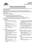
TYPICAL TELEPHONE KEYPAD SHOWING EQUIVALENT COMMAND FUNCTIONS
Key
OFF
1
MAX
AWAY
ABC
TEST†
INST
CODE
PRS
7
3
BYPASS
JKL
MNO
5
6
CHIME
TUV
WXY
8
READY
✱
DEF
2
GHI
4
STAY
9
QUICK–ARM*
OPER
0
#
1
2
3
4
5
6
7
8
9
∗
Function
=
=
=
=
=
=
=
=
=
=
OFF
AWAY
STAY
MAXIMUM
†
TEST
BYPASS
INSTANT
CODE
CHIME
READY
† ON-PREMISES PHONE ONLY
* IF PROGRAMMED
1. You CANNOT initiate a phone “PANIC” from the telephone keypad while in
the thermostat, speaker control, or FA4286 programming mode.
2. To initiate "PANIC" from the telephone keypad refer to "Using the Phone
Panic Feature" in this section.
Performing System Commands
During any pause in the status report, or immediately following it, key the
desired command via the keypad on the phone. Use the same key sequence
indicated for commands in the security system's User Guide.
Example:
To arm AWAY, enter the security code, then press key "2". If
the command entry was successful, two "beeps" will be heard, followed by
voice confirmation, for example, "ARMED AWAY, EXIT NOW."
If you encounter any difficulty with the operation of the phone access system,
refer to Section 5. Troubleshooting in this guide.
4-3
FA4286 VIP Module Installation and Setup Guide
A list of confirmation sounds and voice announcements that follow successful
command entries is provided below.
Confirmation Sounds and Voice Announcements After Command Entries
Command Function
Performed
Telephone Confirmation
Armed AWAY
Sound
2 beeps
Armed MAXIMUM
2 beeps
"ARMED AWAY, EXIT NOW"†
"ARMED MAX, EXIT NOW"†
Synthesized Voice Announcement
Armed STAY
3 beeps
"ARMED STAY, EXIT NOW"†
Armed INSTANT
3 beeps
"ARMED INSTANT, EXIT NOW"†
Disarmed
1 beep
"DISARMED, (NOT) READY TO ARM"
Zone Bypass
1 beep
"BYPASS, (descriptor), ZONE #
Enter CHIME mode
1 beep
"CHIME (ON) or (OFF)"
Enter/Erase temporary User
code*
1 beep
No synthesized voice announcement
† If desired, you may exit during the Exit Delay period.
* This function cannot be performed via the telephone with some controls;
check the control's Installation and Setup Guide.
For those commands where the FA4286 VIP Module's vocabulary does not
provide annunciation, (for example TEST, etc.), a beep will be heard (if appropriate) following a successful entry and the words "SEE SYSTEM
KEYPAD" will be annunciated.
Turning Remote Phone Access On and Off
Remote telephone access to the security system can be toggled on and off via
an on-premises phone (or via a wired keypad) by keying the following:
4-digit Master security code +
#
+
9
+
1
The synthesized voice response will be: “CALL-IN TO SYSTEM [ON] or
[OFF]”, with 2 beeps when turned ON, and 1 beep when turned OFF.
Some systems will not give voice responses, but will give the beeps.
4-4
Section 4. Basic Operating Guide
Remote Access CAN be turned OFF from an off-premises phone, but
CANNOT be turned ON.
If Remote Phone Access has been turned off automatically as a result of tampering (such as would be caused by improper keying of codes on a call-in), and
this occurs repeatedly over a short period of time, the user should be instructed
NOT to turn Remote Phone Access on again for a period of time if the improper
keying was not caused by the user or a family member. An unauthorized
person may be attempting to access the security system from outside.
Installations Where the Telephone System Includes an Answering Machine
When accessing the system via an outside phone when the installation includes an answering machine, enter the 2-digit phone code during the first 20
seconds of the OUTGOING message on the answering machine (preferably
during a pause in the outgoing message), before it begins recording an
incoming message.
The reason for entry of the phone code during a pause is that Touch-tones
(produced by entry of the 2-digit phone code) might not be received by the security system while an answering machine's outgoing voice message is on the
phone line. Also, entering the 2-digit phone code before the answering machine starts recording will prevent the phone code tones from being recorded,
and later played back if the answering machine has a remote message playback feature.
If there is difficulty obtaining phone access when trying to use this
procedure, instruct the end user to re-record the outgoing message on the
answering machine, but leave a 2-second pause at its beginning (for entry of
phone code on an outside call-in).
Example: (2-second pause) “This is the Smith residence. I can't come
to the phone just now… Please leave a message after the tone.”
4-5
FA4286 VIP Module Installation and Setup Guide
End User Relay Command Mode When Using the FA4286 VIP Module
For information on whether operation of the end-user Relay Command mode
via the telephone is possible with the control being used, refer to the control's
Installation and Setup Guide and the following.
Voice feedback is possible only with certain controls.
The following is a summary of the different methods available for manual operation of relays and/or power line carrier devices via the phone in various
First Alert systems. These end user functions are discussed in the FA4286
VIP Module User Guide.
FA142C, FA145C, FA147C
These control panels can use non-voice response relay commands to
manually turn devices on or off. However, field *80 (Output Relay programming) must include.
System Operation choices 34 (Code + # + 7) and/or 35 (Code + # + 8) for
ZT (Zone Type/System Operation) for a selected relay.
When so programmed, the relay for which System Operation choice 34 or
35 was selected can be manually activated or de-activated by keying:
Code + # + 7 or Code + # + 8.
FA148C, FA162C
This control panel uses non-voice response relay commands to manually
turn devices on or off, as follows:
4-digit system code + # + 7 + device No. will turn on the device.
4-digit system code + # + 8 + device No. will turn off the device.
The above mentioned controls will NOT provide voice feedback and there will
be no voice confirmation over the phone that the command has been executed. However, wired keypads in the security system will “beep” for confirmation.
FA1220CV, FA1340C, FA1600C/CA/CB
These control panels use the interactive “# 70 Relay Command Mode” to
manually turn devices on or off.
4-6
Section 4. Basic Operating Guide
Using the Phone Panic Feature
On-premises Touch-tone phones wired as shown in the FA4286 “Summary of
Connections” can be used as panic stations. Program the control as appropriate for “ ✴ # ” keypad panics. See the control panel Installation and Setup
Guide and the FA4286 programming form.
To trigger a panic using the FA4286 VIP Module, instruct the end user to
pick up the handset and first dial in the phone code, then dial in the digit “1”
(at least six times) until you hear dial tone returned, followed by line seizure
(silence). This will activate the “ ✴ # ” keypad panic in the control panel as
long as a report code has been programmed for this panic. Phones incorrectly
wired (connected before the control panel or FA4286 VIP Module) can NOT be
used to gain access to the system or used as panic stations. Refer to the
FA4286 Summary of Connections for correct wiring of the phones. Be sure to
test each phone on the premises to ensure proper operation.
Using the Novice Voice Menu
If the user does not enter a command to the FA4286 within 5 seconds after
the last status message was announced, it would be assumed that help is
needed, and the FA4286 will enter a “novice mode.” The user will then be
prompted to enter the 4-digit system code. If there is no user response to the
system code request, the message will be repeated two more times at 5-second
intervals. At this point, the Module will end the session by saying “GOODBYE, ” and disconnect from the phone line.
If the system code was entered, a voice menu of the more common user commands, (Disarm, Arm-Away, Arm-Stay, Relay Control, and Thermostat Control) will be provided. Again, if there is no user response, the menu will be
repeated two more times at 5-second intervals. At this point, the voice Module will end the session by saying “GOOD-BYE, ” and disconnect from the
phone line.
The FA4286 VIP Module does not differentiate between correct and incorrect
system codes; that is the function of the control panel. If the system code is not
entered correctly, the control panel will not respond to the commands. After a 5second pause, the user will again be prompted to “ENTER SYSTEM CODE
NOW. ” At this time, the user may enter the correct system code.
If the system code was correctly entered, the control panel will respond with a
status message as it usually does. The “novice mode” will be re-entered 5 seconds later.
4-7
FA4286 VIP Module Installation and Setup Guide
About the Speaker Output
Pressing “✴ ✴” on the monitored keypad will trigger a status announcement
from the speaker output (except if the user has made the MUTE speaker control menu selection. User command confirmation for Entry/Exit, Alarm, and
other warnings can also be provided.
The speaker output is for auxiliary use only and is not intended to replace the
system’s primary sounder or siren.
When using an output speaker, announcements made by the speaker will be
limited. All faults that exist may not be announced when status is called for. This
will prevent lengthy voice reports through the output speaker that some users
may find objectionable.
4-8
S E C T I O N
5
Troubleshooting
• • • • • • • • • • • • • • • • • • • • • • • • • • • • • • • • • • • • • • • • • •
In This Section
♦ Typical System Problems and Solutions
• • • • • • • • • • • • • • • • • • • • • • • • • • • • • • • • • • • • • • • • • •
"87" Displayed on Keypad and Rapid
Beeping Occurs (and/or the system cannot be accessed by phone).
• The FA4286 VIP Module is not responding
to the control panel. Check wiring of
FA4286 VIP Module to control (Data In,
Data Out, Aux [+], and Aux [–] wiring).
Keypad Does Not Function.
• If addressed incorrectly, keypads will not
display or beep. If using an FA142C,
FA145C, FA147C, FA148C, or FA162C
control, keypads must be set to the nonaddressable mode (31).
Security System Cannot Be Accessed via
the Phone (on or off premises).
• The 2-digit Phone Code has not been programmed.
• 2nd digit of Phone Code (✴ or #) does not
provide touch tones on phone in use. Select whichever of these digits that does. If
neither does, that phone is not usable for
phone access.
Security System Cannot Be Accessed via
the Phone (from on premises).
• Entry of 2-digit phone code may be incorrect. Verify phone code and try again.
• Generally, the system cannot be accessed
when the phone line is busy, such as when
downloading is in progress, if engaged in a
phone conversation (except during entry
delay), or when the phone is ringing (always allow at least 10 seconds after the
last ring before attempting phone access)
• The system cannot be accessed if the
phone line is out of service.
Note: If the system cannot be access by
phone, verify the phones were properly
wired to the security system as shown in
the Summary of Connections. Phones incorrectly wired (connected before the control panel or FA4286 VIP Module) can
NOT be used to gain access to the system.
Security System Cannot Be Accessed via
the Phone (from off premises).
• Either the 2-digit phone code or system
security code may have been entered incorrectly. Verify both codes and try again.
• Remote access turned off. If so, turn on
(from on-premises phone only) by entering
2-digit Phone Code to access system, then
enter: Master security code + # + 9 + 1.
Note: If turned off and TAMPER message
is displayed, clear system first by keying
an OFF sequence twice.
5-1
FA4286 VIP Module Installation and Setup Guide
Remote Phone Access Keeps Turning Off
Automatically.
• Improper keying (or attempted tampering)
from an outside phone has automatically
turned remote phone access off (the keypad will display a tamper message).
No Tones Produced By the Touch-tone
Phone When Keys Are Pressed (onpremises phone).
• Phone is not Touch-tone capable. If
switchable type, make sure phone is
switched to TONE.
• It may be necessary to reverse wires connected to terminals 3 and 4 on FA4286
VIP Module and "Handset" TIP and RING
terminals on control (see section describing wiring connections for FA4285/
FA4286).
The System Has Been Accessed and
Status Reports Annunciated, But Commands Cannot Be Executed.
• Key entries may have been too rapid –
make key entries slowly and firmly.
• You may have keyed entries while the system was speaking. Make your key entries
only during pauses in annunciations by
the system.
• Security code entered may be incorrect.
• Certain command functions have restrictions. Entry to the control panel programming mode cannot be executed via
the phone (see below). TEST and "Sniffer
modes can be initiated from an onpremises phone only.
Cannot Initiate "Panic"
• Verify Phone Panic Address in Field 01;
Control Panel Type in Field 02; 2-digit
phone code, and panic code (six 1’s) have
5-2
been entered correctly. Both Field 01 and
02 relate to the VIP Programming Mode.
There must be no Modules or keypads
with their address set to the phone panic
address. Verify the control panel has “✴
#” panic programmed for the correct zone
type and report code. Also verify the device address used for phone panics is programmed for use by a keypad.
Cannot Enter Temporary User Codes via
the Phone
This function cannot be performed via the
phone with some controls – only at the
keypad. See the control's Installation and
Setup Guide for information.
Descriptions Of Zones Not Annunciated
Along With Zone Numbers.
• Zone descriptors have not been programmed (necessary even if system uses
only fixed-word keypads).
• Words selected for descriptors are in the
control panel's vocabulary of words but are
not in the FA4286 VIP Module's vocabulary (see "Programming Zone Descriptors").
Thermostat is in “CHECK” (FA4286
announces “Check Thermostat”, or
the yellow light is flashing on the
4500):
• Check that the dip switch on each thermostat is properly set, and that the 4500 addresses have been properly programmed
in the FA4286 programming mode.
• Check the connections from the FA4286 to
the 4500, and make sure that the cable
connecting the 4500 to the FA4286 faces
the correct direction—yellow toward the
corner of the FA4286 board.
In an FA1220CV, FA1340C, or
FA1600C/CA/CB Installation, Descriptions of Zones Annunciated Are Not
Correct.
"See System Keypad" Message Is Annunciated.
This message will be annunciated during
any of the following conditions:
1. When the system is in the TEST mode.
2. When the system has been set to the
House or Transmitter ID "Sniffer" modes.
3. Four or more unsuccessful attempts have
been made to access the system from offpremises, which has caused Remote
Phone Access to be turned off.
4. Low battery in an RF transmitter.
5. Modem connection with PC downloader
(down-loading in progress).
6. There has been a failure of the system to
communicate with the central station.
7. There has been a 4281 or 5881 Receiver
Set Up Error (more RF zones have been
programmed than can be accommodated
by the type of receiver used).
When the "See System Keypad" message
is annunciated under the conditions listed
in 1 through 7 above, the keypad will provide the display normally expected under
those particular conditions. For example:
1. If System is in the TEST mode. In this
mode, a fixed-word keypad only displays
the normal "System Disarmed" message,
while an Alpha key-pad displays "Test in
Progress", unless a zone is faulted, in
which case the zone number (and the description if it is an Alpha keypad) of the
open zone is displayed. If System is in the
House or Transmitter ID "Sniffer" mode.
Any display that appears is used to identify ID numbers for specific identification
Section 5. Troubleshooting
purposes in this mode (used only during
system installation).
2. If "Tampering" has caused "CALL-IN
TO SYSTEM OFF, SEE SYSTEM
KEYPAD" message to be annunciated.
If system is in disarmed mode, an Alpha
keypad displays "CALL-IN TAMPER"
and a fixed-word keypad displays "CI".
However, if system is in armed mode,
only the normal "System Armed" message
is displayed.
3. If there is a low battery in an RF
Transmitter. If system is in the disarmed state, a "Low Battery" message is
displayed. If system is in the armed
state, this display message may not appear until system is disarmed (depending
on how the system was programmed).
4. If Downloading is in progress. During
this period, the Alpha keypad displays
"MODEM COMM" and the fixed-word
keypad displays "CC."
5. If there is failure of communication
with the central station. If system has
attempted to send a report to the central
station and failed, the Alpha keypad displays "COMM FAILURE" and the Fixedword keypad displays "FC."
6. If there is incorrect programming of
RF zones for the 4281 or 5881 Receiver. If more RF zones have been programmed than can be accommodated by
the receiver in use, an Alpha keypad displays "RCVR Set-Up Error," and a Fixedword keypad displays "E8."
5-3
FA4286 VIP Module Installation and Setup Guide
5-4
S E C T I O N
6
Appendices
• • • • • • • • • • • • • • • • • • • • • • • • • • • • • • • • • • • • • • • • • •
In This Section
♦ In the Event of Trouble with Regular Telephone Service
♦ Federal Communications Commission (FCC) Part 15 and Part 68 Statement
♦ Telco-Provided Coin Service Advisement
♦ Summary of Connections
♦ First Alert Professional Limited Warranty
• • • • • • • • • • • • • • • • • • • • • • • • • • • • • • • • • • • • • • • • • •
In The Event Of Trouble With Regular Telephone Service
In the event of trouble with regular telephone service, disconnect the security system from
the phone lines by removing the plug from the RJ31X (CA38A in Canada) wall jack. We
recommend that you demonstrate removal of this plug to the user, following installation of
the system.
Do not disconnect the phone connection inside the Control or the FA4286 VIP
Module. Doing so will result in the loss of regular phone service.
If the regular phone works correctly after the plug has been disconnected from the RJ31X
(CA38A in Canada) wall jack, the Control Panel or the FA4286 VIP Module has a problem
and the faulty unit should be returned for repair. If upon disconnection of the plug, there is
still a problem on the line, the telephone company should be notified that they have a
problem and that prompt repair service is needed.
IMPORTANT: If the phone service is at fault in the test above, re-insert the plug immediately; if the security system is at fault, re-insert the plug as soon as the security system is
repaired, since the security system relies on this connection for communication with the
alarm monitoring station.
The user may not under any circumstances (in or out of warranty) attempt any service or
repairs to the system. It must be returned to the factory or an authorized service agency
for all repairs.
A-1
FA4286 VIP Module Installation and Setup Guide
FEDERAL COMMUNICATIONS COMMISSION (FCC) PART 15 STATEMENT
This equipment has been tested to FCC requirements and has been found acceptable for use. The FCC requires
the following statement for your information:
This equipment generates and uses radio frequency energy and if not installed and used properly, that is, in
strict accordance with the manufacturer's instructions, may cause interference to radio and television reception.
It has been type tested and found to comply with the limits for a Class B computing device in accordance with the
specifications in Part 15 of FCC Rules, which are designed to provide reasonable protection against such interference in a residential installation. However, there is no guarantee that interference will not occur in a particular
installation. If this equipment does cause interference to radio or television reception, which can be determined
by turning the equipment off and on, the user is encouraged to try to correct the interference by one or more of
the following measures:
• If using an indoor antenna, have a quality outdoor antenna installed.
• Reorient the receiving antenna until interference is reduced or eliminated.
• Move the receiver away from the security control.
• Move the antenna leads away from any wire runs to the security control.
• Plug the security control into a different outlet so that it and the receiver are on different branch circuits.
If necessary, the user should consult the dealer or an experienced radio/television technician for additional suggestions. The user or installer may find the following booklet prepared by the Federal Communications Commission helpful: "Interference Handbook". This booklet is available from the U.S. Government Printing Office,
Washington, DC 20402. The user shall not make any changes or modifications to the equipment unless authorized by the Installation Instructions or User's Manual. Unauthorized changes or modifications could void the
user's authority to operate the equipment.
FEDERAL COMMUNICATIONS COMMISSION (FCC) PART 68 STATEMENT
This equipment complies with Part 68 of the FCC rules. On the front cover of this equipment is a label that contains, among other information, the FCC registration number and ringer equivalence number (REN) for this
equipment. If requested, this information must be provided to the telephone company.
This equipment uses the following jacks: An RJ31X is used to connect this equipment to the telephone network.
The REN is used to determine the quantity of devices which may be connected to the telephone line. Excessive
RENs on the telephone line may result in the devices not ringing in response to an incoming call. In most, but
not all areas, the sum of the RENs should not exceed five (5.0). To be certain of the number of devices that may
be connected to the line, as determined by the total RENs, contact the telephone company to determine the
maximum REN for the calling area.
If this equipment causes harm to the telephone network, the telephone company will notify you in advance that
temporary discontinuance of service may be required. If advance notice is not practical, the telephone company
will notify the customer as soon as possible. Also, you will be advised of your right to file a complaint with the
FCC if you believe necessary.
The telephone company may make changes in its facilities, equipment, operations, or procedures that could affect
the operation of the equipment. If this happens, the telephone company will provide advance notice in order for
you to make the necessary modifications in order to maintain uninterrupted service.
If trouble is experienced with this equipment, please contact the manufacturer for repair and warranty information. If the trouble is causing harm to the telephone network, the telephone company may request you remove the
equipment from the network until the problem is resolved.
There are no user serviceable components in this product, and all necessary repairs must be made by the manufacturer. Other repair methods may invalidate the FCC registration on this product. This equipment cannot be
used on telephone company-provided coin service. Connection to Party Line Service is subject to state tariffs.
This equipment is hearing-aid compatible.
A-2
Section 6. Appendices
TELCO-PROVIDED COIN SERVICE ADVISEMENT:
This equipment cannot be used on telephone company-provided coin service. Connection to Party Line
Service is subject to state tariffs.
This equipment is hearing-aid compatible.
When programming or making test calls to emergency numbers, briefly explain to the dispatcher the reason for the call. Perform such activities in the off-peak hours; such as early morning or late evening.
A-3
FA4286 VIP Module Installation and Setup Guide
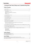
SPEAKER NOTE: IF CONNECTING SINGLE SPEAKER, USE 8-ohm SPEAKER ONLY.
IF CONNECTING 2 SPEAKERS, USE 4-ohm or 8-ohm SPEAKERS
AND CONNECT IN SERIES.
P3 SPEAKER
VOLUME
CONTROL
NO
CONNECTION
GREY
BROWN
KEYED
HEADER
EARTH
GROUND
TO CONTROL PANEL
KEYPAD CONNECTIONS
YELLOW
GREEN
4500
THERMOSTAT
THE 4500 THERMOSTAT
CAN NOT BE USED IN
UL INSTALLATIONS.
TIP RING TIP RING
HANDSET INCOMING
TELCO LINE
TIP
RING
PREMISES
CALLER ID UNIT,
ANSWERING
MACHINE, AND
PHONES
CALLER ID
UNIT
ANSWERING
MACHINE
YELLOW
NO CONNECTION
RED
BLACK
GREEN
IMPORTANT NOTE FOR EXISTING INSTALLATIONS:
EXISTING WIRES CONNECTED TO THE “HANDSET”
TERMINALS ON CONTROL MUST BE MOVED FROM
THERE TO TERMINALS 3 AND 4 ON THE 4286.
THIS DEVICE COMPLIES WITH FCC RULES, PART 68
FCC REGISTRATION No. AC3USA-74659-KX-N
RINGER EQUIVALENCE: 1.0B
U.S. PATENT No. 4791658
Summary of Connections
A-4
INCOMING TELCO LINE
TIP
RJ31X
JACK RING
GREEN
RED
LOUDER
NOTE:
4286 DEVICE
ADDRESS IS
FACTORY SET
TO “4”
SEE SPEAKER NOTE
1 2 3 4 5 6 7
4286 VIP MODULE
FIRST ALERT PROFESSIONAL LIMITED WARRANTY
First Alert Professional Security Systems, a Division of Pittway Corporation, and its divisions, subsidiaries and affiliates ("Seller"), 175 Eileen Way, Syosset, New York 11791, warrants its products to be in conformance with its own
plans and specifications and to be free from defects in materials and workmanship under normal use and service for
18 months from the date stamp control on the product or, for products not having an First Alert date stamp, for 24
months from date of original purchase unless the installation instructions or catalog sets forth a shorter period, in
which case the shorter period shall apply. Seller's obligation shall be limited to repairing or replacing, at its option,
free of charge for materials or labor, any product which is proved not in compliance with Seller's specifications or
proves defective in materials or workmanship under normal use and service. Seller shall have no obligation under this
Limited Warranty or otherwise if the product is altered or improperly repaired or serviced by anyone other than First
Alert Professional factory service. For warranty service, return product transportation prepaid, to First Alert Professional Factory Service, 175 Eileen Way, Syosset, New York 11791.
THERE ARE NO WARRANTIES, EXPRESS OR IMPLIED, OF MERCHANTABILITY, OR FITNESS FOR A
PARTICULAR PURPOSE OR OTHERWISE, WHICH EXTEND BEYOND THE DESCRIPTION ON THE FACE
HEREOF. IN NO CASE SHALL SELLER BE LIABLE TO ANYONE FOR ANY CONSEQUENTIAL OR INCIDENTAL
DAMAGES FOR BREACH OF THIS OR ANY OTHER WARRANTY, EXPRESS OR IMPLIED, OR UPON ANY
OTHER BASIS OF LIABILITY WHATSOEVER, EVEN IF THE LOSS OR DAMAGE IS CAUSED BY THE SELLER'S
OWN NEGLIGENCE OR FAULT.
Seller does not represent that the products it sells may not be compromised or circumvented; that the products will
prevent any personal injury or property loss by burglary, robbery, fire or otherwise; or that the products will in all
cases provide adequate warning or protection. Customer understands that a properly installed and maintained alarm
may only reduce the risk of a burglary, robbery, fire or other events occurring without providing an alarm, but it is not
insurance or a guarantee that such will not occur or that there will be no personal injury or property loss as a result.
CONSEQUENTLY, SELLER SHALL HAVE NO LIABILITY FOR ANY PERSONAL INJURY, PROPERTY DAMAGE
OR OTHER LOSS BASED ON A CLAIM THE PRODUCT FAILED TO GIVE WARNING. HOWEVER, IF SELLER IS
HELD LIABLE, WHETHER DIRECTLY OR INDIRECTLY, FOR ANY LOSS OR DAMAGE ARISING UNDER THIS
LIMITED WARRANTY OR OTHERWISE, REGARDLESS OF CAUSE OR ORIGIN, SELLER'S MAXIMUM
LIABILITY SHALL NOT IN ANY CASE EXCEED THE PURCHASE PRICE OF THE PRODUCT, WHICH SHALL BE
THE COMPLETE AND EXCLUSIVE REMEDY AGAINST SELLER. This warranty replaces any previous warranties
and is the only warranty made by Seller on this product. No increase or alteration, written or verbal, of the obligations
of this Limited Warranty is authorized.
SEE THE CONTROL PANEL'S INSTALLATION INSTRUCTIONS FOR
REGARDING THE LIMITATIONS OF THE ENTIRE SECURITY SYSTEM.
COMPLETE
INFORMATION
175 Eileen Way, Syosset, New York, 11791
Copyright © 1999 PITTWAY CORPORATION
¬1§l
N6431-1 11/9