1
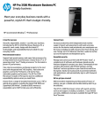
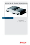
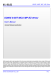
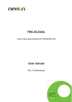
MP-III Writer User Manual
SONiX 8-Bit MCU MP-III Writer
User Manual
V1.0
SONIX reserves the right to make change without further notice to any products herein to improve reliability, function or design.
SONIX does not assume any liability arising out of the application or use of any product or circuit described herein; neither does it
convey any license under its patent rights nor the rights of others. SONIX products are not designed, intended, or authorized for us as
components in systems intended, for surgical implant into the body, or other applications intended to support or sustain life, or for any
other application in which the failure of the SONIX product could create a situation where personal injury or death may occur. Should
Buyer purchase or use SONIX products for any such unintended or unauthorized application. Buyer shall indemnify and hold SONIX
and its officers, employees, subsidiaries, affiliates and distributors harmless against all claims, cost damages, and expenses, and
reasonable attorney fees arising out of, directly or indirectly, any claim of personal in jury or death associated with such unintended or
unauthorized use even if such claim alleges that SONIX was negligent regarding the design or manufacture of the part.
SONiX TECHNOLOGY CO., LTD.
Version 1.0
MP-III Writer User Manual
MANUAL REVISION HISTORY
Version
V1.0
Date
Mar. 2007 First Issue
SONiX TECHNOLOGY CO., LTD.
Description
Page 2
Version 1.0
MP-III Writer User Manual
INDEX
MANUAL REVISION HISTORY .....................................................................................................................................2
1
MP-III WRITER INTRODUCTION ..................................................................................................................... 4
1.1
1.2
1.3
1.4
1.5
2
OFFLINE PROGRAMMING OPERATION OF CHIP........................................................................................ 9
2.1
2.2
2.3
3
MP-III W RITER OFFLINE OPERATION MENU AND RELATIVE MESSAGE ILLUSTRATION................................................18
MP-III W RITER OPTION DESCRIPTION ..................................................................................................................19
COMMON TROUBLESHOOTING .................................................................................................................. 20
5.1
5.2
6
THE ONLINE PROGRAMMING STEPS OF CHIP .........................................................................................................10
ROLLING CODE SETTING .....................................................................................................................................15
EEPROM OPERATION .......................................................................................................................................16
MP-III WRITER OFFLINE OPERATION ILLUSTRATION ............................................................................. 18
4.1
4.2
5
OFFLINE PROGRAMMING STEPS OF CHIP ................................................................................................................9
DOWNLOAD PROGRAMMING CODE .........................................................................................................................9
CHIP OFFLINE PROGRAMMING ...............................................................................................................................9
ONLINE PROGRAMMING OPERATION OF CHIP........................................................................................ 10
3.1
3.2
3.3
4
GUIDE .................................................................................................................................................................4
FUNCTION OUTLINE ..............................................................................................................................................4
HARDWARE INTRODUCTION ..................................................................................................................................4
ACCESSORY ILLUSTRATION ..................................................................................................................................5
SOFTWARE AND HARDWARE INSTALLATION ...........................................................................................................7
ENTER TEST MODE ............................................................................................................................................20
COMMON TROUBLESHOOTING METHOD ..............................................................................................................20
APPENDIX....................................................................................................................................................... 21
SONiX TECHNOLOGY CO., LTD.
Page 3
Version 1.0
MP-III Writer User’s Manual
1
MP-III Writer INTRODUCTION
1.1 Guide
MP-III Writer is new generation writer based on MP-I Writer, extends with USB port and ISP (In
System Program) function, download program code and updates the programming control
procedure through USB port. It changes hardware update to software update and
accommodates customer with convenient usage.
1.2 Function outline
Adapted Flash Base MCU with ISP function, chip programming control procedure can be
updated according to requirement at online status.
It’s convenient to connect Full Speed USB 1.1 port with PC and then update the writer, connect
programming chip or download programming code.
Supporting chip connection and operation at offline status.
Succeeding all functions of MP-I Writer.
New function of reading data from chip online.
New functions of reading data from EEPROM and clearing EEPROM.
1.3 Hardware introduction
MP-III Writer contains base control board, programming upper-board and programming
transition board and case. Message description is shown in table 1, outward appearance is
shown in figure 1.
No.
(1)
(2)
Feature
S3
S1
Description
RESET Key
MODE Key
Four digits 7
Segment Display
(3)
D6
(4)
D1~D3
Indicative LED
(5)
S2
Execution Key
(6)
JP2
Writer Transition
Board Socket
(7)
JP1&JP
3
MP Transition
Board
(8)
Text Tool
Programming
Base
SONIX TECHNOLOGY CO., LTD.
Remark
Reset Writer
Function Mode Choosing
Display Programming Message and
Function Indication
Programming Status Indication. Green light
means programming finished, yellow light
means still programming, red light means
failure.
execute the programming procedure or
break
alarm indication
used for connecting wire aboard to
programming chip
used for insert in programming transition
board, it must be matched with MCU series
no.
deposit chips waited for programming (only
fitting to DIP or can turn to DIP package)
Table 1
Page 4
Version 1.1
MP-III Writer User’s Manual
(1)
(2)
(3)
(4)
(5)
(6)
(7)
(8)
Figure 1 MP-III Writer outward appearance
1.4 Accessory Illustration
5 wired Mini USB wire is used to connect MP-III with PC, as shown below
Figure 2 USB Cable
DC 7.5V/2A direct current power supply, used for MP-III working power source.
Programming extend with 20 pins bus, as shown below
Figure 3 20 pins bus
MP programming transition board, match with different chips, used for programming
control wire connected with chip programming pin, as shown below. Using the
SONIX TECHNOLOGY CO., LTD.
Page 5
Version 1.1
MP-III Writer User’s Manual
programming transition board can directly deposit the chip with DIP package onto 48
pins text tool to program.
SONIX TECHNOLOGY CO., LTD.
Page 6
Version 1.1
MP-III Writer User’s Manual
Figure 4 MP transition board inserted in JP1 & JP3
V3 programming transition board (shared with Writer 3.0), as shown below:
Figure 5 Transition board shared with Writer 3.0
1.5 Software and Hardware Installation
1.5.1 Software Install
1. The software MPIII_Wt.exe supporting to this type of writer is embedded in SN8IDE_1.99W
(supporting SN8P1910 series MCU), M2IDE_V112 (supporting Sn8P2000 series MCU) or in
compilation software with updated version. User can surf to website of SONiX to download and
upgrade this software.
2. Installing driver procedure to use MP-III Writer is needed first time, according PC instruction to choose
compile software file SN8USBMP3Wt.inf under the portfolio “\USB_Driver”.
3. Using this software with MP-III writer can download the programming code to the EEPROM of writer
and proceed with chip programming offline and directly programming online. For detail operation
please refer to relative part mentioned lately.
1.5.2 Hardware Install
1. Install corresponding series no. MP programming transition board or V3 programming transition board,
as shown in figure 6:
Figure 6 MP-III Writer and programming transition board connection diagram
2. Connecting DC 7.5V/2A DC power.
3. Utilizing Mini USB Cable to connect writer with PC.
4. Execute software file (ex. MPIII_WtV100.exe) supporting this type of writer and download the file .SN8
SONIX TECHNOLOGY CO., LTD.
Page 7
Version 1.1
MP-III Writer User’s Manual
waited for programming to the EEPROM of writer.
5. The communication operation between programming and PC (operations like downloading the file
SN8, programming online etc) need to see the 7-segments displayer display the word “USB” and then
proceed with next operation (if the instruction is not shown, please push RESET key or check the
connection).
6. Without connecting USB Cable, after the power of writer is on or pushing the RESET key, 7-segments
displayer will show “the type of chip version - no. of firmware”, then display programming code
(including the type of MCU and the value of checksum) restored in EEPROM.
7. If the EEPROM equip with writer is damaged or dismounted artificially, the error message indication
“Err4” will be shown.
8. The direction of deposition diagram of OTP MCU is shown below or refer to the case identification of
writer.
Figure 7 The diagram of chip deposition
SONIX TECHNOLOGY CO., LTD.
Page 8
Version 1.1
MP-III Writer User’s Manual
2
OFFLINE PROGRAMMING OPERATION OF CHIP
2.1 Offline programming steps of chip
Step1: download the programming code
Step2: offline programming of chip
2.2 Download programming code
Connecting DC 7.5V/2A power line, USB wire with MP-III Writer respectively:
Switching writer to USB online mode:
Open the programming software online and download the programming code .SN8 to EEPROM,
and note the checksum value, for detail operation please refer to chapter 3:
Remove USB Cable, writer will reset and enter the offline mode automatically. Choosing Fun5
through pressing “Mode” and “Enter” keys and check the checksum of EEPROM to see if it is
same with the record value.
Programming code download is finished.
2.3 Chip offline programming
Dismount the case of writer and then stick to MP programming transition board or using 20pins
bus to connect V3 transition board:
Connect DC 7.5V/2A power, the default working mode of writer is FUN6:
After 7-segments displayer show “the type of chip waited for programming - Checksum value”,
then deposit the MCU waited for programming, press the “Enter” key to program, the execution
action is “Program + Verify”, OK indication light brighten after programming successfully:
For detail operation please refer to chapter 4.
SONIX TECHNOLOGY CO., LTD.
Page 9
Version 1.1
MP-III Writer User’s Manual
3
ONLINE PROGRAMMING OPERATION OF CHIP
3.1 The online programming steps of chip
Start the operation interface of MP-III Writer software, default selection “programming MCU”, the
Simplified Chinese interface.
E
F
G
A
B
I
J
H
C
D
Figure 8 MP-III software opening frame
Interface message illustration:
A
B
C
D
E
F
G
H
I
J
Installation of chip programming code button.
The display frame of chip type.
Function button choosing area.
Setting Rolling Code function button, only can be configured after
starting rolling code.
Path display area of chip programming code.
Display area of chip programming code, indicate whether the function
of encryption is opened simultaneously..
Status display area, like Program, Read …etc.
Programming message indication frame.
The firmware version of programming procedure.
Language selection button providing with Simplified Chinese and
English to choose.
SONIX TECHNOLOGY CO., LTD.
Page 10
Version 1.1
MP-III Writer User’s Manual
Click “Device/Load SN8” button, choose programming code of the needed chip type, shown as
below:
Figure 9 choose chip type & programming code
If the connection of MP-III Writer and PC is normal, after finishing last step, programming code
will be automatically downloaded to EEPROM of writer, programming indication message is
shown in figure 10. The function button will bulge out to echo operation.
Figure 10 download the programming code to EEPROM
SONIX TECHNOLOGY CO., LTD.
Page 11
Version 1.1
MP-III Writer User’s Manual
If only choose type of chip, choose to cancel programming code, interface will back to opening
status, all function button will be invalid, as shown in figure 8.
After chip waited for programming deposited to fixture correctly and click “Auto Program” button,
writer will execute “Blank Check”, “Program”, “Verify” at once, indication message is shown as
figure 11:
Figure 11 Execute “Auto Program”
Click “Blank Check” button, only make a blank check to chip, shown as figure 12:
Figure 12 execute “Blank Check” function
SONIX TECHNOLOGY CO., LTD.
Page 12
Version 1.1
MP-III Writer User’s Manual
Click “Program” button, only execute chip programming action, shown as below:
Figure 13 Programming OTP finished
Click “Verify” button, only check whether the code programmed to chip is correct or not, correct
data verification is shown in figure 14, error data verification will show error address and error
data as shown in figure 15:
Figure 14 Verification, data correct
SONIX TECHNOLOGY CO., LTD.
Page 13
Version 1.1
MP-III Writer User’s Manual
Figure 15 Verification, data error
Click “Read OTP” button, will read message from chip (if chip is encrypted then only part of data
can be read), and shown in message frame, as shown below. In addition, one file .BBB will
automatically generate and be restored under the portfolio of the compilation software called
“Wirter_log”.
Figure 16 Read the data of OTP
SONIX TECHNOLOGY CO., LTD.
Page 14
Version 1.1
MP-III Writer User’s Manual
3.2 Rolling code setting
Only the function of Rolling Code is used, the button “Rolling Code” is effect.
Click “Rolling Code” button, the dialogue box is shown as next figure, the option of initial address,
length, initial value and step value can be modified.
Figure 17 Rolling Code setting
After finishing rolling code setting, click “ok”, the setting of data will be updated synchronous in
writer and INI deposition file.
In the process of programming rolling code, writer switch the online mode to offline mode, don’t
affect the correct variation of rolling code. For example: initial value is 0001, after programming
two chip online, then the value of rolling code will start from 0003.
SONIX TECHNOLOGY CO., LTD.
Page 15
Version 1.1
MP-III Writer User’s Manual
3.3 EEPROM operation
At MP-III Writer online status, after choosing the option “Operation of EEPROM”, the options of
“read EEPROM”, “clear EEPROM” can be carried out with the EEPROM of Writer.
Figure 18 the interface of EEPROM operation
After clicking “Device/Load SN8” button, the chip type and programming code can be selected,
as shown below:
Figure 19 Choose MCU type and programming code in the interface of operating EEPROM
SONIX TECHNOLOGY CO., LTD.
Page 16
Version 1.1
MP-III Writer User’s Manual
Clicking “read EEPROM” button can read the data from EEPROM and shown in message frame,
as shown below. A .BBB file will be generated automatically and restored under the portfolio of
compilation software called “Writer_log”.
Figure 20 read EEPROM
Clicking “clear EEPROM” button will clear the valid data of EEPROM, as shown below:
Figure 11 clear EEPROM
NOTE:
:After clearing EEPROM, if don’t download SN8 file to writer and execute the
programming, writer will alarm and display “Err4”.
SONIX TECHNOLOGY CO., LTD.
Page 17
Version 1.1
MP-III Writer User’s Manual
4
MP-III Writer Offline Operation Illustration
4.1 MP-III Writer offline operation menu and relative message
illustration
Mode
Function Outline
Executing
7-segmen
LED
ts
displayer
Success
7-segments LED
displayer
Failure
7-segment LED
s
displayer
FUN1
Auto1:
Blank + Program +
Verify
Blank Check
FUN2
Program
none
Yellow
FUN3
Verify
none
Yellow
Checksum
value or
Rolling Code
FUN1
FUN2
or
Rolling Code
Checksum
FUN4
Read OTP
none
Yellow
Checksum
FUN5
Read EEPROM
none
Yellow
FUN6
Auto2:
Program + Verify
none
Yellow
Checksum
Checksum
Err2
or
Rolling Green
or Err3
Code
FUN0
FUN7
FUN8
Remark
none
Yellow
none
Yellow
Green
Err1,Err2,E
rr3
Red
Green Err1
Red
Green Err2
Red
Green Err3
Uncertain
Green
value
Green Err4
Red
Red
Red
Display Rolling Code
none
Yellow Lowest word Green
value
ex
:
Display
firmware
none
Yellow
Green
name and version no.
2704A-F101
1. After starting writer, the default is “FUN6”, different mode can be selected through
clicking “MODE” button.
2. Checksum value: choose it equal to Security checksum with encryption, equal to
EEPROM checksum without encryption.
2. Rolling Code: In Fun0, Fun2 and Fun6 mode, if Rolling Code is used, show the lowest
bit value of Rolling Code.
3. FUN8 can check chip type and the firmware version of writer, ex: “2704A-F101”, “2704A”
are MCU type, “F101” are the firmware version of writer.
No.
1
2
3
4
5
6
Error Message
Err0
Err1
Err2
Err3
Err4
Err6
SONIX TECHNOLOGY CO., LTD.
Message description
VPP voltage error
OTP Blank Check failure
OTP programming failure
OTP programming verification failure
EEPROM vacant or data unusual
Programming pin with bad contact or
error direction deposition.
Page 18
Version 1.1
MP-III Writer User’s Manual
4.2 MP-III Writer option description
After downloading SN8 file to EEPROM of MP-III Writer, insert MP transition board or V3
transition board, deposit chip correctly then proceed with the operation of offline programming
(need to remove USB Cable).
MP-III Writer is power on, check whether the data of EEPROM is correct or not, the message
“Err4” is shown if data is error, if data is correct then display MCU type and the firmware version
of writer, then display the word “EEP-“, display the type of MCU waited for programming and
checksum consequently.
After power on, the default operation mode is FUN6 (Auto2), press “Enter” button to proceed
programming. Auto2 means execute Program + Verify action, if programming error occur,
7-segments displayer will show error message, meanwhile, the buzzer alarm, press “Enter” key
or dismount IC to cancel the alarm.
Utilizing “MODE” and “Enter” keys to select execution functions.
Executing the operations “Blank Check”, “Program”, “Verify”, “Read” to chip, 7-segments
displayer display nothing, yellow indication light brighten, after finishing the corresponding
message will show.
MP-III Writer can support Rolling Code programming, only need to open Rolling Code function
while downloading programming code to EEPROM, and set the relative parameters at the same
time. Every time after programming one chip, 7-segments displayer will display the message of
the lowest word of programming Rolling Code. If the programming failed, the value of Rolling
Code will remain invariable, after programming success, the value of Rolling Code will be
modified at next programming time, the value of programming rolling code of the current writer
can be enquired through FUN7.
MP_III Writer leave the factory equipped with 24LC256 typed EEPROM, space is up to 16K
word. Please don’t change other type in order to avoid error.
MP_III Writer need some specified message in the aspect of message setting, so the
corresponding programming software have to be used.
SONIX TECHNOLOGY CO., LTD.
Page 19
Version 1.1
MP-III Writer User’s Manual
5
Common Troubleshooting
5.1 Enter Test Mode
Open the case of MP-III writer, remove the transition board and chip waited for programming, push “Enter”
button and don’t release, push “RESET” button again, the “Test mode” can be entered. Three green, red and
yellow indicative LED display in circle in “Test Mode” status, buzzer can generate regular indicative sound.
User can utilize adjusted multi-meter to measure the value of voltage VPP whether the value of voltage is
about 12.7V or not. Push “RESET” key again, make the writer back to normal operation mode.
5.2 Common Troubleshooting Method
Err0 represent the voltage VPP or VXX is error.
Possible trouble source: upper-board (the part of step up circuit in transition board, L1, D1, U1,
Q1 etc).
Err1 represent Blank Check Fail.
Possible trouble source: text tool, transition board.
Err2 represent Program Fail
Possible trouble source: text tool, transition board or upper-board (R41~43, R56).
Err3 represent Verify Fail.
Possible trouble source: upper-board (R41~43, R56).
Err4 represent Read or Write EEPROM fail
Possible trouble source: the fluctuating voltage lead to data changing in EEPROM
(reload .SN8 file is ok), EEPROM is damaged, EEPROM.
Err6 represent IC is not contact well.
Possible trouble source: text tool, transition board.
SONIX TECHNOLOGY CO., LTD.
Page 20
Version 1.1
MP-III Writer User’s Manual
6
APPENDIX
AppendixⅠ
Ⅰ MP-III Writer Master Control Procedure Driver Update
It’s very simple to upgrade MP-III Writer software. Please surf to SONiX website constantly to
check if upgraded IDE software is released, re-install can finish the software upgrading. Chip
mater driver name, version, driver and the programming supported MCU type table is shown
below:
Chip Mater Driver Name
Driver
2501B-F101
2602B-F101
And So On
SN8P2501B.drv
SN8P2602B.drv
…
Supporting MCU
type
SN8P2501B
SN8P2602B
…
MP-III Writer and MPI Writer, EZ Writer and Writer3.0 comparison table
Supporting
Supporting
7-segme
Online
Online
nts
48-pins
Writer
Port
Power
Programmin
Programmin displayer
Test Tool
g
g
interface
MP-III
Yes
USB
Yes
Yes
DC 7.5V
Yes
MPI
Printe
No
Yes
Yes
DC 7.5V
Yes
r
EZ
ICE
No
No
No
None
Yes
Port
Writer
Printe
No
Yes
No
DC 15V
No
3.0
r
Supportin
gRolling
Code
Yes
Yes
Yes
No
AppendixⅡ
Ⅱ Accessory listing
Name of
Accessory
MP-III Writer
USB Cable
DC Power
MP Transition
Board
20-Pins双母座排线
Status
Standard Equipment
Standard Equipment
Standard Equipment
Additional Equipment
Standard Equipment
Description
Consist of programming upper-board, control lower-board and
case
Used for connecting with PC
7.5V/2.0A
Attach to writer, deposited according to MCU type customer
indicated
Used for bus connected to V3 transition board
AppendixⅢ
Ⅲ 7-segments display 0~9, A~F font
SONIX TECHNOLOGY CO., LTD.
Page 21
Version 1.1
MP-III Writer User’s Manual
AppendixⅤ transition board pins correspondent
JP1/JP2 of writer
VSS 2
CE 4
OE/ShiftDat 6
D0 8
D2 10
D4 12
D6 14
VPP 16
RST 18
ALSB/PDB 20
1 VDD
3 CLK/PGCLK
5 PGM/OTPCLK
7 D1
9 D3
11 D5
13 D7
15 VDD
17 HLS
19 -
JP1 for MP transition board
JP3 of writer (Mapping to 48-pin text tool)
DIP1
DIP2
DIP3
DIP4
DIP5
DIP6
DIP7
DIP8
DIP9
DIP10
DIP11
DIP12
DIP13
DIP14
DIP15
DIP16
DIP17
DIP18
DIP19
DIP20
DIP21
DIP22
DIP23
DIP24
1
2
3
4
5
6
7
8
9
10
11
12
13
14
15
16
17
18
19
20
21
22
23
24
48
47
46
45
44
43
42
41
40
39
38
37
36
35
34
33
32
31
30
29
28
27
26
25
DIP48
DIP47
DIP46
DIP45
DIP44
DIP43
DIP42
DIP41
DIP40
DIP39
DIP38
DIP38
DIP36
DIP35
DIP34
DIP33
DIP32
DIP31
DIP30
DIP29
DIP28
DIP27
DIP26
DIP25
JP3 for MP transition board
SONIX TECHNOLOGY CO., LTD.
Page 22
Version 1.1
MP-III Writer User’s Manual
JP2: Connecting to V3 transition board through 20pins bus, if making V3 transition board
artificially is needed, please refer to every type programming corresponding pins table in next
article.
JP1/JP3: Utilizing TEXT TOOL to program IC, be sure to insert the corresponding type of MP
transition board in JP1/JP3, OTP pin1 waited for programming is corresponded to JP3 pin1,
OTP pin2 is corresponded to JP3 pin2 and so on.
Please pay attention: Making MP transition board artificially, the pin1 of JP1 and JP3 is shown in
next figure (near right):
SONIX TECHNOLOGY CO., LTD.
Page 23
Version 1.1
MP-III Writer User’s Manual
SONIX reserves the right to make change without further notice to any products herein to improve reliability, function or design.
SONIX does not assume any liability arising out of the application or use of any product or circuit described herein; neither does it
convey any license under its patent rights nor the rights of others. SONIX products are not designed, intended, or authorized for us as
components in systems intended, for surgical implant into the body, or other applications intended to support or sustain life, or for any
other application in which the failure of the SONIX product could create a situation where personal injury or death may occur. Should
Buyer purchase or use SONIX products for any such unintended or unauthorized application. Buyer shall indemnify and hold SONIX
and its officers, employees, subsidiaries, affiliates and distributors harmless against all claims, cost damages, and expenses, and
reasonable attorney fees arising out of, directly or indirectly, any claim of personal in jury or death associated with such unintended or
unauthorized use even if such claim alleges that SONIX was negligent regarding the design or manufacture of the part.
Main Office:
Address: 9F, NO. 8, Hsien Cheng 5th St, Chupei City, Hsinchu, Taiwan R.O.C.
Tel: 886-3-551 0520
Fax: 886-3-551 0523
Taipei Office:
Address: 15F-2, NO. 171, Song Ted Road, Taipei, Taiwan R.O.C.
Tel: 886-2-2759 1980
Fax: 886-2-2759 8180
Hong Kong Office:
Address: Flat 3 9/F Energy Plaza 92 Granville Road, Tsimshatsui East Kowloon.
Tel: 852-2723 8086
Fax: 852-2723 9179
Technical Support by Email:
[email protected]
SONIX TECHNOLOGY CO., LTD.
Page 24
Version 1.1