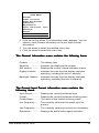
1
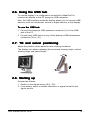
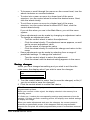
B4100339 / 01
September 2003
© 2003 BARCO NV. All rights reserved
BarcoView
Theodoor Sevenslaan 106
8500 Kortrijk, Belgium
Phone: +32(0)56 23 32 44
Fax: +32(0)56 23 33 74
E-mail: [email protected]
http://www.barcoview.com
BarcoView Inc
3059 Premiere Parkway
Duluth, Georgia, 30097,USA
Phone: +1 678 475 8000
Fax: +1 678 475 8100
E-mail: [email protected]
http://www.barcoview.com
BarcoView LTD
16F-1, Cheng Loong Plaza 33, Min Sheng Road
Section 1, Pan Chiao, Taipei Hsien, Taiwan, R.O.C.
Phone: +886 2 2957 8357
Fax: +886 2 2957 4080
MFGD 2320
User Manual
CONTENTS
1.Overview ............................................................................................................ 6
1.1. Introduction .............................................................................................. 6
1.2. Package contents .................................................................................... 7
1.3. Controls and connectors ......................................................................... 8
Front ........................................................................................................... 8
Side ............................................................................................................ 8
Rear ........................................................................................................... 9
2. Installation ..................................................................................................... 10
2.1. Precautions ........................................................................................... 10
2.2. Before installing the display .................................................................. 10
2.3. Portrait or landscape position ................................................................ 11
2.4. Connecting the signals .......................................................................... 11
2.5. Routing the signal cables ...................................................................... 13
2.6. Using the USB hub ................................................................................ 14
2.7. Tilt and swivel positioning ...................................................................... 14
2.8. Starting up ............................................................................................. 14
3. Operation ...................................................................................................... 15
3.1. Switching to stand-by position ............................................................... 15
3.2. Controlling the display ........................................................................... 15
About the on-screen menus .................................................................... 15
Navigating through the menus ................................................................. 15
Saving changes ....................................................................................... 16
3.3. Using the Autoset* functions ................................................................. 17
When do you need to use the Autoset functions? ................................... 17
Required test pattern ............................................................................... 17
To enter the Autoset menu: ...................................................................... 17
The Autoset menu contains the following items: ..................................... 18
3.4. Controlling Video Contrast* and Video Brightness* .............................. 18
To enter the menu: ................................................................................... 18
To change Video Contrast or Video Brightness manually: ...................... 19
To select the calibrated position: ............................................................. 19
Additional information .............................................................................. 19
3.5. Setting the Luminance value ................................................................. 19
3.6. Making adjustments .............................................................................. 20
How to make the adjustments? ............................................................... 20
Geometry adjustments ............................................................................. 21
Phase adjustments* ................................................................................. 22
3.7. Selecting inputs ..................................................................................... 22
To enter the Inputs menu: ........................................................................ 22
You can select the following input selection settings: .............................. 23
3.8. Settings ................................................................................................. 23
To enter the Settings menu: ..................................................................... 23
The Settings menu contains the following items: .................................... 24
3.9. Preset .................................................................................................... 24
To enter the Preset menu: ....................................................................... 24
The Preset menu contains the following items: ....................................... 25
3.10 Getting information ............................................................................... 25
To enter the Information menu: ................................................................ 25
The General Information menu contains the following items: ................. 26
The Current Input Format information menu contains the following items:26
4. Advanced functions ....................................................................................... 27
4.1. About this chapter ................................................................................. 27
About the Advanced functions ................................................................. 27
To log in as advanced user: ..................................................................... 27
4.2. Advanced functions in the Adjustments menu ..................................... 28
Geometry ................................................................................................. 28
Ambient Light Compensation .................................................................. 28
Low Pass Filter* ....................................................................................... 29
4.3. Advanced functions in the Settings menu ............................................. 29
Display function ....................................................................................... 29
Input Mode ............................................................................................... 29
OSD position ............................................................................................ 31
4.4. Advanced functions in the Preset menu ................................................ 31
Clear user presets ................................................................................... 31
4.5 Advanced functions in the Information menu ......................................... 31
Service ..................................................................................................... 31
Firmware .................................................................................................. 32
Runtimes .................................................................................................. 32
5. Maintenance ................................................................................................. 33
Panel ........................................................................................................ 33
Cabinet ..................................................................................................... 33
Removing dust from the rear of the glass panel ...................................... 33
6. Troubleshooting ............................................................................................ 34
Windows does not show the desired display settings .................................. 34
Pixel Faults ................................................................................................... 34
7. Technical specifications ................................................................................ 35
SAFETY INSTRUCTIONS
Read the safety and operating instructions
before operating the apparatus.
Retain safety and operating instructions for
future reference.
Adhere to all warnings on the apparatus and
in the operating instructions manual.
Follow all instructions for operation and use.
This app
aratus conforms to
apparatus
to: CE, IEC 60950,
UL 60950, CAN/CSA C22.2 No. 950-95 (cUL)
Usage in Hazardous locations
Class I equipment
Equipment not suitable for use in the presence
of a flammable anesthetic mixture with air or
with oxygen or nitrous oxide.
FCC notice
This equipment has been tested and found to
comply with the limits of a class A digital device,
pursuant to Part 15 of the FCC rules. These
limits are designed to provide reasonable
protection against harmful interference when
the equipment is operated in a commercial
environment. This equipment generates, uses
and can radiate radio frequency energy and, if
not installed and used in accordance with the
instruction manual, may cause harmful
interference to radio communications.
Operation of this equipment in a residential
area is likely to cause harmful interference in
which case the user will be required to correct
the interference at his own expense.
Power connection
• Power requirements: The apparatus must
be powered using the 12 VDC power supply
that is supplied with the apparatus. The 12
VDC power supply must be powered by the
AC mains voltage.
User manual MFGD 2320
• Power cord with CEE 7 plug ( ): The colors
of the mains lead are colored in accordance
with the following code: Green-and-yellow:
Earth (safety earth), Blue: Neutral, Brown:
Line
• Power cord with ANSI 73.11 plug ( ): The
wires of the power cord are colored in
accordance with the following code: Green/
yellow: ground, White: neutral, Black: line
(live)
• Power requirements: connect the apparatus
to an AC voltage as indicated at its back. Using
a lower voltage, the apparatus will not be able
to operate. Using a higher voltage may
damage the apparatus. If you are not sure of
the type of power supplied, consult the power
company.
• Do not overload wall outlets and extension
cords as this may result in fire or electric
shock.
• Mains lead protection (U.S.: Power cord):
Supply cords should be routed so that they
are not likely to be walked upon or pinched
by items placed upon or against them, paying
particular attention to cords at plugs and
receptacles.
Water and moisture
Never expose the apparatus to rain or
moisture.
Never use the apparatus near water - e.g. near
a bathtub, washbasin, swimming pool, kitchen
sink, laundry tub or in a wet basement.
Ventilation
Do not cover or block the ventilation openings
in the cover of the set. When installing the
apparatus in a cupboard or another closed
location, heed the necessary space between
the set and the sides of the cupboard.
Inst
allation
Installation
Place the apparatus on a flat, solid and stable
surface that can bear the weight of at least 3
monitors. If you use an unstable cart or stand,
the set may fall, causing serious injury to a
child or adult, and serious damage to the
equipment.
More warnings in the Installation chapter.
3
1. OVER
VIEW
OVERVIEW
1.1. Introduction
The MFGD 2320, BARCO’s 20” 2 megapixel grayscale LCD display,
guarantees perfect image quality in medical imaging applications.
The display combines a TFT (thin film transistor) liquid crystal display
panel structure and a built-in backlight with inverter for a better picture
quality. It is designed to meet the users’ needs for performance,
consistency, and outstanding image quality through a streamlined
development process.
If the Portrait Accelerator option is installed, the display can be used
in portrait or landscape version, simply by turning the panel. The tilt &
swivel foot allows ideal positioning of the panel, in height and viewing
angle.
The panel can be adjusted by means of a control wheel on the
display.
I-Guard
I-GUARD® is Barco’s patent-pending, built-in calibration device,
continuously maintaining image quality. With I-GUARD®, QA checks
no longer need to disturb normal radiology activities, as they can be
performed while applications are running.
I-GUARD® allows radiologists or QA administrators to calibrate their
viewing stations or adjust the panel’s curve to DICOM standards
without administrator intervention.
Autoset feature
The display has an Autoset feature that helps the user to adjust
standard presets: With one single function, you can automatically
adjust the display completely.
Autoscan
When you connect a video signal, the display checks in the internal
memory if the signal has been adjusted before. If so, it selects the
settings and parameters that match the connected signal.
When you connect a video signal that hasn’t been connected before,
and adjust the display to the signal, the adjustments and signal timing
parameters are stored in a programmable preset.
User manual MFGD 2320
4
Best resolution
The optimum and recommended resolution is 1600 x 1200 or 1200 x
1600 (if the Portrait Accelerator option is installed).
The recommended refresh rate is 60 Hz.
Would you have trouble selecting a proper display setting in
Windows, please refer to the Troubleshooting section further
further..
BARCO’s BarcoMed 2MP2FH imaging board is the best choice to
drive the MFGD 2320 display.
Power saving (DPMS)
The MFGD 2320 is equipped with a power saving system.
When left idle for a certain time, the computer connected to the
display, will power down the display. The power saving system can be
switched on or off using the on-screen menus.
This system requires a computer imaging board that supports power
saving management.
Ambient Light Compensation (ALC)
When enabled, the ALC system automatically adapts the display light
output, depending on the ambient light in the room. The ambient light
is measured by the ALC optical sensor located at the front of the
display.
1.2. Package content
s
contents
The package should include the following items, please check. If
some of the items are missing, please contact the reseller from whom
you have purchased the unit.
-
The MFGD 2320 display
-
Power supply
-
DVI cable
-
Analog video cable
-
USB cable
-
Two velcro strips to bind the cables
-
European power cord
-
American power cord
-
This user manual
If the display is part of a Coronis system, the package contains more
items. Please refer to the packing list on the outside of the Coronis
box.
User manual MFGD 2320
5
1.3. Controls and connectors
Front
(1) Ambient Light Compensation (ALC) sensor
(2) Power LED
-
The LED is off when the display is off.
-
The LED is green when the display is on (when enabled in the onscreen menus).
-
The LED is orange when the display is in Stand-by power-saving
mode.
1
2
Side
(3) USB downstream connector
(4) Control wheel for navigating through the on-screen display (OSD)
menus and changing values in the menus
4
3
User manual MFGD 2320
6
Rear
(5)
Digital DVI (video and data) input
(6)
D15 (VGA) video connector
(7)
Vertical sync input
(8)
Composite / Horizontal sync input
(9)
Composite video input
(10) USB downstream connector
(11) USB upstream connector
(12) DC 12V power input
DVI
5
User manual MFGD 2320
D15
VS
CS/HS
VIDEO
6
7
8
9
10
11
12
7
2. INST
ALLA
TION
INSTALLA
ALLATION
2.1. Precautions
•
Keep your original packaging. It is designed for this display and is
the ideal protection during transport.
•
Avoid reflections in the flat panel to reduce eye strain.
•
Place the display on a strong and stable table or desk.
•
Keep the display away from heat sources and provide enough
ventilation in case it is built in a rack or console.
•
Make sure all equipment is switched off before connecting the
signals.
2.2. Before inst
alling the display
installing
Import
ant:
Important:
In the factory, the height-positioning system in the display foot is
blocked with a strap to prevent damage during transportation.
Before installing the display, you must remove this strap.
Strap
To remove the strap:
1 Position the display with its rear side facing you.
2 Lift up the 2 clips of the foot cover to release the cover from the
foot.
3 Pull the lower side of the cover towards you and simultaneously
slide the cover downward.
4 Pull the red strap out of the fixation holes in the foot.
You can better leave the cover off the foot while connecting the signal
cables to the display.
User manual MFGD 2320
8
2.3. Portrait or landscape position
You can change the orientation of the panel at any time, but it is more
convenient to select landscape or portrait orientation before connecting the cables.
To change the panel orientation:
1 Stand at the front side of the panel and take the panel at both
sides.
anel before changing the orient
ation.
2 Very important: Tilt the p
panel
orientation.
Should you change the panel orientation without tilting it first, you
might irreversibly damage the tilt & swivel mechanism.
3 To change from portrait to landscape, turn the panel
counterclockwise while tilting it slightly.
To change from landscape to portrait, turn clockwise.
2.4. Connecting the signals
To get access to the connectors, open the cover of the connector
compartment by pulling down the 2 clips of the cover.
The signal cables can be routed inside the display foot. Therefore,
remove the foot cover before connecting the signals (see "Before
installing the display").
Import
ant:
Important:
Do not connect video and sync signals to the BNC and D15 connectors at the same time.
To connect DVI signals:
1 Connect one end of the DVI cable to the DVI input (5) of the
display.
2 Connect the other end of the DVI cable to the video output of your
DVI signal source.
3 Route the cable so that it enters the connector compartment at the
place where the cover is bulged.
User manual MFGD 2320
9
To connect analog video & sync signals on BNC:
Connect the video & sync output of the signal source to the video and
sync inputs (9), (8) and (7) of the display.
The inputs accept the following signals:
• Video with separate horizontal and vertical sync.
-
The connection consists of 3 cables.
Connect the video signal to the connector Video (9).
Connect the horizontal sync signal to the connector HS/CS (8).
Connect the vertical sync signal to the connector VS (7).
Make sure the signal connected to the HS/CS connector
does not cont
ain Composite sync.
contain
• Video with external composite sync.
The connection consists of 2 cables.
Connect the video signal to the connector Video (9).
Connect the composite sync signal to the connector HS/CS (8).
Make sure no signal is connected to the VS connector
connector..
• Video with internal composite sync (sync on video).
The connection consists of 1 cable.
Connect the video (with sync) signal to the connector Video (9).
Notes
Notes:
•
The video inputs cannot be connected in loop-through (daisy-chain).
•
The required video amplitude: 700 mV ± 3 dB.
•
The required sync. amplitude:
- VS input: 700 mV to 4 V
- HS/CS input: 500 mV to 4V
- Video input (sync on video): 150 mV to 600 mV
To connect analog video & sync signals on D15:
1 Connect one end of the VGA cable to the D15 input (6) of the
display.
2 Connect the other end of the VGA cable to the video output of your
computer.
3 Route the cable so that it enters the connector compartment at the
place where the cover is bulged.
To connect the power:
1 Connect the output of the 12V DC power supply to the DC input (12)
of the display.
2 Connect one end of the proper power cable to the AC input of the
12V DC power supply.
User manual MFGD 2320
10
3 Connect the other end of the power cord to a grounded power
outlet.
4 Route the cable so that it enters the connector compartment at the
place where the cover is bulged.
Connect to DC
input of the display
Connect one end of
power cable
2.5. Routing the signal cables
After connecting all cables, fix them in the cable tie at the rear of the
connector compartment. Bind the cables together above and under
the foot, by means of the 2 velcro strips included in the package.
After fixing the cables, put the connector compartment cover back in
place. Pay attention that the signal cables are positioned under the
bulge in the cover.
Next, fix the cables in the plastic clamps on the foot. At last, put the
foot cover back in place.
To put the foot cover in place:
1 Push the upper side of the cover onto the foot, so that the hooks
on the cover are positioned right under the holes in the foot.
2 Slide the cover upward while moving the lower side of the cover
towards the foot.
3 Press the cover to the foot so that both clips make a clicking
sound.
Connector
compartment
Push the upper side of
the cover onto the foot
User manual MFGD 2320
Signal cables routed under foot cover
and bound by velcro strips
11
2.6. Using the USB hub
To use the display in a configuration controlled by MediCal Pro,
connect the display to the PC using the USB connector.
Also, the USB interface inside the display allows you to connect USB
devices, such as a keyboard, mouse or digital camera, to the display.
To use the USB hub:
1 Connect the display’s USB upstream connector (11) to the USB
port of the PC.
2 Connect any USB device to any of the display’s USB downstream
connectors (3) or (10).
2.7. Tilt and swivel positioning
Adjust the position of the panel for best viewing conditions.
The display foot allows adjusting the horizontal viewing angle, vertical
viewing angle and panel height.
2.8. S
Sttarting up
Proceed as follows:
1 Switch on the signal source (E.g., PC).
2 If necessary, select a suitable resolution or signal format for the
signal source.
User manual MFGD 2320
12
3.
OPERA
TION
OPERATION
3.1. Switching to st
and-by position
stand-by
When the display is on and no on-screen menus are visible, press the
control wheel (4) for a few seconds to switch the display in stand-by.
When the display is in stand-by, press or turn the control wheel to
switch it back on.
3.2. Controlling the display
The control wheel (4) at the bottom (landscape orientation) or at the
side (portrait orientation) allows you to perform controls.
The control wheel is a rotation - click system. It provides the following
functions:
•
Short click: Enter menus, confirm selections, and toggle between
different options
•
Rotate: Browse through menus, increase or decrease adjustment
values
About the on-screen menus
•
The content of the on-screen menus depends on the selected
video input: Some of the functions are present in the analog
modes (BNC and DB15) but are not present in DVI mode.
•
The functions that are not present in DVI mode are indicated
with an * throughout this manual.
Navigating through the menus
•
The menu system has a hierarchical structure, with several levels.
To display the on-screen menus, turn the wheel (4). The Main
Menu appears. This is the top level of the menu system.
MFGD 2320
MAIN MENU
Autoset*
Video Contrast*
Video Brightness*
Luminance
Adjustments
Input Selection Auto
Settings
Preset
Information
EXIT
User manual MFGD 2320
* Not in DVI mode
13
•
To browse or scroll through the menus on the current level, turn the
wheel clockwise or counterclockwise.
•
To enter into a menu or move to a lower level of the menu
structure, turn the control wheel to select the desired menu. Next,
click the wheel shortly.
•
To exit from a menu or move to a higher level of the menu
structure, turn the control wheel to select EXIT. Next, click the
control wheel shortly.
If you do this when you are in the Main Menu, you exit the menu
system.
•
Some adjustments can be made by changing an adjustment value.
To change an adjustment value:
-
•
Turn the control wheel to select the adjustment
Click the wheel shortly. The adjustment name appears, as well
as the current adjustment value
Turn the wheel to change the value
Click the wheel shortly to confirm the change and return to the
menu
Some adjustments can be made by selecting from a range of
predefined settings. To change the selection:
-
Turn the control wheel to select the adjustment
Click the wheel until the desired setting appears in the menu.
Saving changes
When you have changed something and you wish to exit from the
main menu, the display asks if you wish to save the changes.
Save Changes?
Yes
No
1 Turn the control wheel to select Yes (to save the changes) or No (if
you do not wish to save the changes).
2 Click the control wheel to confirm the choice.
Info
Info: The memory of the display contains maximum 200 fixed and 28
programmable presets.
When you connect a video signal, the display checks in the memory for a
matching preset.
If it finds one, it selects the corresponding settings and parameters from the
memory. If it does not find a matching preset, the display uses default settings
to display the image.
When you make adjustments and save the changes, the current preset is
saved as programmable preset. If this happens while all programmable
presets are occupied, the oldest programmable preset is overwritten automatically.
User manual MFGD 2320
14
3.3. Using the Autoset* functions
* Not in DVI mode
The Autoset menu provides a set of functions to adjust the display
automatically.
When do you need to use the Autoset functions?
It is necessary to perform the Auto Gain and Auto Phase calibrations
in the following cases:
•
The first time you use the display on an analog video
•
After connecting or selecting another analog video source
It is necessary to perform the Automatic Geometry function in case
you notice the image geometry or positioning is not as desired.
Required test pattern
To obtain good results with the autoset functions, it is necessary to
have a good image on which to perform the functions.
For Auto Geometry, the pattern should be an image that is filled up to
the edges, from left to right and top to bottom. The edges of the image
should have an intensity of at least 15% video amplitude. E.g., a
Windows desktop pattern would be a good image.
For Auto Phase, the pattern should contain sharp black-white transitions, like a line pattern or characters.
For Auto Gain, the pattern should contain parts that are completely
black (0% video amplitude) and parts that are full white (100% video
amplitude).
To enter the Autoset menu:
1 In the main menu, turn the control wheel to select the Autoset
menu.
MFGD 2320
MAIN MENU
Autoset*
Video Contrast*
Video Brightness*
Luminance
Adjustments
Input Selection Auto
Settings
Preset
Information
EXIT
User manual MFGD 2320
* Not in DVI mode
15
2 Click the control wheel. The Autoset menu appears.
AUTOSET
Full Autoset
Automatic Geometry
Automatic Phase
Automatic Gain
EXIT
3 Turn the control wheel to select the function you wish to execute.
4 Execute the function as described below.
The Autoset menu contains the following items:
Full Autoset ................. Click the control wheel to perform all Autoset
functions (below) one after another.
Automatic Geometry ... Click the control wheel to adjust the image
geometry automatically. This function measures the start and the end of the incoming
video signal. It displays the complete active
video in the center of the screen and, if the
active video is smaller than the native panel
resolution and no scaling is selected (see
further), it puts black borders around the active
video window.
Automatic Phase ......... Click the control wheel to adjust the video
sampling phase and frequency automatically
Automatic Gain ........... Click the control wheel to adjust the video
levels (black and white) automatically
3.4.
Controlling V
ideo Contrast* and V
ideo
Video
Video
Brightness*
* Not in DVI mode
To enter the menu:
1 In the main menu, turn the control wheel to select the Video
Contrast or Video Brightness menu.
2 Click the control wheel to enter the Video Contrast or Video
Brightness menu. You can change the current setting manually or
select the calibrated position.
User manual MFGD 2320
16
To change Video Contrast or Video Brightness manually:
1 Turn the control wheel to select the manual Contrast (Brightness)
control.
VIDEO CONTRAST
Contrast CAL position
Man Contrast adj
EXIT
2 Click the control wheel to enter the control.
3 Turn the control wheel to change the Video Contrast or Video
Brightness value.
4 Click the control wheel to confirm the change of the value.
5 Turn the control wheel to select EXIT. Next, click the control wheel
shortly to return to the Main menu.
To select the calibrated position:
1 Turn the control wheel to select the "Set to Cal position" selection
menu.
VIDEO CONTRAST
Contrast CAL position
Man Contrast adj
EXIT
2 Click the control wheel to switch to the calibrated position.
3 Turn the control wheel to select EXIT. Next, click the control wheel
shortly to return to the Main menu.
Additional information
-
If you change Video Contrast or Video Brightness manually, the
changed value is saved in the memory.
3.5. Setting the Luminance value
With this function, the backlight value is stabilized by the I-Guard
sensor. The value you enter is the target backlight luminance, expressed in Cd/m².
User manual MFGD 2320
17
Proceed as follows:
1 In the main menu, turn the control wheel to select the Luminance
menu.
MFGD 2320
MAIN MENU
Autoset
Video Contrast*
Video Brightness*
Luminance
Adjustments
Input Selection Auto
Settings
Preset
Information
EXIT
2 Click the control wheel. The Luminance menu appears.
3 Turn the control wheel to adjust the luminance target value.
4 Click the control wheel to return to the main menu.
3.6. Making adjustment
s
adjustments
How to make the adjustments?
1 In the main menu, turn the control wheel to select the Adjustments
menu.
MFGD 2320
MAIN MENU
Autoset
Video Contrast*
Video Brightness*
Luminance
Adjustments
Input Selection Auto
Settings
Preset
Information
EXIT
2 Click the control wheel. The Adjustments menu appears.
ADJUSTMENTS
Geometry
Phase*
EXIT
* Not in DVI mode
User manual MFGD 2320
18
3 Turn the control wheel to select the adjustment menu you wish to
enter: Geometry or Phase.
4 Click the control wheel to enter the menu.
5 Turn the control wheel to select the adjustment you wish to execute.
6 Click the control wheel.
7 Execute the adjustment as described below.
Geometry adjustments
The Geometry menu contains the following items:
Automatic Geometry* .... This is the same function as in the Autoset
menu. Please refer to the description of the
Autoset functions above. After Automatic
Geometry, the image is centered inside the
active video window. Its size depends on the
video resolution and the Scaling setting.
Hor Pos* ........................ Turn the control wheel to position the image
horizontally inside the active video window
Vert Pos* ....................... Turn the control wheel to position the image
vertically inside the active video window
Scaling .......................... Click to select the desired scaling option:
- None:
- Best Fit:
The image is not scaled
The image is scaled
proportionally to obtain the best
fit
- Full Screen: The image is scaled nonproportionally to fill the screen
both horizontally and vertically
Orientation** ............ Click to select the desired option:
- Auto:
The display selects portrait or
landscape reproduction
automatically, depending on the
orientation of the panel.
- Portrait:
The image is reproduced in
portrait orientation.
- Landscape: The image is reproduced in
landscape orientation.
* Not in DVI mode
** Available only if the Portrait Accelerator option is installed
User manual MFGD 2320
19
Phase adjustments*
* Not in DVI mode
Required test pattern
To obtain good results, it is necessary to have a good image on which
to perform the functions.
For the Phase adjustments, the pattern should contain sharp blackwhite transitions, like a line pattern or characters.
The Phase menu contains the following items:
Automatic Phase ..... Click the control wheel to adjust the video
sampling phase and frequency automatically
Frequency ............... Turn the wheel to adjust the video sampling
frequency manually
Man Phase adj ........ Turn the wheel to adjust the video sampling
phase manually
We recommend you use the automatic adjustment routine only. The
manual controls are intended for advanced users who wish to finetune the result of the automatic routine.
3.7. Selecting input
s
inputs
To enter the Inputs menu:
1 In the main menu, turn the control wheel to select the Input
Selection menu.
MFGD 2320
MAIN MENU
Autoset
Video Contrast*
Video Brightness*
Luminance
Adjustments
Input Selection Auto
Preset
Settings
Information
EXIT
* Not in DVI mode
User manual MFGD 2320
20
2 Click the control wheel. The Input Selection control appears.
3 Turn the wheel to select the desired input setting.
4 Click the wheel to activate the input selection and return to the
main menu.
You can select the following input selection settings:
Auto ......................... If Automatic is selected, the display automatically selects the input to which a video signal is
connected. If more than one video signal is
connected, priority is given to DVI, followed by
DB15 and BNC in this order.
DVI .......................... Click the control wheel to select the DVI input.
Consequently, the Automatic setting will be
switched off.
DB15 ....................... Click the control wheel to select the DB15 (VGA)
input. Consequently, the Automatic setting will be
switched off.
BNC ........................ Click the control wheel to select the BNC inputs.
Consequently, the Automatic setting will be
switched off.
3.8. Settings
To enter the Settings menu:
1 In the main menu, turn the control wheel to select the Settings
menu.
MFGD 2320
MAIN MENU
Autoset
Video Contrast*
Video Brightness*
Luminance
Adjustments
Input Selection Auto
Settings
Preset
Information
EXIT
* Not in DVI mode
2 Click the control wheel. The Settings menu appears.
User manual MFGD 2320
21
3 Turn the wheel to select the desired menu item.
4 Perform the settings as described below.
The Settings menu contains the following items:
DPMS .......................... Click the control wheel to switch on/off the
automatic power saving system (DPMS)
Power LED .................. Click to switch the power LED on/off. Note:
The LED's orange DPMS state is not influenced by this setting. So, when the display
goes into power-saving mode, the LED will
turn orange, even if it was switched off by this
setting.
User Controls .............. Click to disable the control wheel functions so
that the on-screen display cannot be used
after quitting the OSD menus.
To enable the control wheel functions
again
again:
a) Do not use the wheel for at least 3 seconds
b) Turn the control wheel 1 click clockwise
c) Click the control wheel 2 times
d) Turn the control wheel 1 click counterclockwise
e) Select the Settings menu and switch Local
controls on again.
Actions b, c, d have to be performed in a
sequence that ttakes
akes no longer than 3
seconds.
Ambient Light Compensation .... Click to switch the Ambient Light
Compensation system (ALC) on/off.
Automatic Menu Exit ... Click to switch the automatic menu exit feature
on/off. When switched on, the OSD menus
automatically close when left idle for some
time.
3.9. Preset
To enter the Preset menu:
1 In the main menu, turn the control wheel to select the Preset
menu.
User manual MFGD 2320
22
MFGD 2320
MAIN MENU
Autoset
Video Contrast*
Video Brightness*
Luminance
Adjustments
Input Selection Auto
Settings
Preset
Information
EXIT
* Not in DVI mode
2 Click the control wheel. The Preset menu appears.
3 Turn the wheel to select the desired menu item.
4 Perform the settings as described below.
The Preset menu contains the following items:
(Re)name ................ You can change the name of the preset in the
programmable memory location only. Turn the
control wheel to change the current character.
Click the wheel to move to the next character.
Find next preset ...... Select if you wish to select another preset from
memory that matches the incoming video and
sync signals. The number displayed in the OSD
is the number of the actual preset's memory
location.
3.10 Getting information
The Information menu allows you to get information about the display
and the connected signals.
To enter the Information menu:
1 In the main menu, turn the control wheel to select the Information
menu.
User manual MFGD 2320
23
MFGD 2320
MAIN MENU
Autoset
Video Contrast
Video Brightness
Luminance
Adjustments
Input Selection Auto
Settings
Preset
Information
EXIT
2 Click the control wheel. The Information menu appears. You can
select to view General information or Current Input Format
information.
3 Turn the wheel to select the desired menu item.
4 Click the wheel to select the menu item.
The General Information menu contains the following items:
Product .................... The display type
Serial No ................. Indicates the display serial number
SW Version ............. Displays the current internal software version
Display Lifetime ...... Indicates the total time the display has been
operating, including the time in stand-by
Backlight Lifetime .... Indicates the total time the display has been
operating, excluding the time in stand-by
The Current Input Format information menu contains the
following items:
Input Source ............ Displays the currently selected input
Preset ...................... Displays the currently selected memory preset
Preset Name ........... The name of the current memory preset
Hor Frequency ........ The currently measured horizontal sync frequency
Vert Frequency ........ The currently measured vertical sync frequency
Resolution ............... Displays the actual video signal resolution
User manual MFGD 2320
24
4.
ADV
ANCED FUNCTIONS
ADVANCED
4.1. About this chapter
Import
ant
Important
The functions described in this chapter are intended for trained
service staff only!
Improper use of these functions may disorder the display. BARCO
cannot be held responsible for the results or damage caused by
improper use of these functions.
This chapter describes only the Advanced functions in the OSD
menus. For a description of the other functions (standard functions),
please refer to the previous chapter, Operation .
In this chapter, we assume the advanced user knows how to use the
OSD system: How to browse through the menus, how to enter menus
and sub-menus, how to select and change values.
These actions are described in the previous chapter.
About the Advanced functions
The advanced functions are extensions of the OSD menus. A standard user browsing through the OSD system sees only the standard
functions. When logged in in advanced mode, the user sees the
standard and advanced functions in the OSD menus.
To log in as advanced user:
1 Enter the main menu.
2 Turn the control wheel to select the menu item EXIT.
3 Click and hold the control wheel for a few seconds until the OSD
main menu is refreshed on the screen.
You have now logged in as advanced user.
User manual MFGD 2320
25
4.2. Advanced functions in the Adjustment
s
Adjustments
menu
Geometry
In Advanced mode, the Geometry menu additionally contains the
following functions:
Hor Active ................ Allows you to change the horizontal size of the
active video window around the image, expressed in pixels. If you decrease this size, you
may blank a part of the image.
Vert Active ............... Allows you to change the vertical size of the
active video window around the image, expressed in pixels. If you decrease this size, you
may blank a part of the image.
Ambient Light Compensation
Ambient Light Compensation is sometimes abbreviated to ALC. See
Introduction.
The Ambient Light Compensation menu contains the following items:
Min ALC .................. Contains two functions to set the minimum point
of the ALC control system:
-
Measure Min Ambient Light: Decrease the
light in the room to the minimum possible
level you are likely to work in. Next, execute
this function.
-
Min Luminance: Adjust this value until the
luminance is at the level you wish to work
with when the ambient light is at the minimum level you have set in the above function.
Max ALC .................. Contains two functions to set the maximum point
of the ALC control system:
- Measure Max Ambient Light: Decrease the
light in the room to the maximum possible
level you are likely to work in. Next, execute
this function.
- Max Luminance: Adjust this value until the
luminance is at the level you wish to work with
when the ambient light is at the maximum level
you have set in the above function.
User manual MFGD 2320
26
Low Pass Filter*
* Not in DVI mode
The display electronics provide 4 different low-pass filters to filter
possible high-frequent distortion from an analog video signal.
Select a different filter in case the image contains high-frequent noise
or distortion. Select the filter that gives the best result.
Readjustment of sample phase is necessary after selection of a
different filter.
4.3.
Advanced functions in the Settings menu
The Settings menu contains the following advanced functions:
Display function
The display contains a number of factory-defined and user-defined
Display functions (LUTs).
Turn the control wheel to select a display function.
-
-
Select a DICOM display function for most medical viewing
applications. The DICOM function results in more visible
grayscales in the images.
Select a CRT (gamma) display function in case the display is used
to replace a CRT display.
-
LUT 3 and LUT 4 are user-programmable display functions
(dedicated software needed).
-
If you select None
None, no display function will be selected.
-
The selection Test LUT is meant for internal test purposes. It
should not be selected for normal operation.
Input Mode
To change the Input Mode setting, click the control wheel. Turn the
wheel to select Standard or Extended input mode. Then click the
wheel again to enter the selected submenu.
The following input mode settings can be selected:
Standard input mode
RGB->Y ................... The RGB video signals from the imaging board
are calculated and transformed into a single
luminance value according to the formula
0.3R + 0.59G + 0.11B. This single luminance
signal drives the RGB sub-pixels of the panel
equally.
User manual MFGD 2320
27
Use this setting in case the imaging board is a
color board.
RGB->RGB ............. The R video signal drives the R sub-pixels, the G
video signal drives the G sub-pixels and the B
video signal drives the B sub-pixels. This is the
preferred setting for grayscale imaging boards
that have the luminance signal on all 3 video
channels, because it ensures the most levels of
gray.
G->Y ........................ The Green video signal from the imaging board
is used as luminance value to drive the RGB
subpixels of the panel equally.
B->Y ........................ The Blue video signal from the imaging board is
used as luminance value to drive the RGB
subpixels of the panel equally.
R->Y ........................ The Red video signal from the imaging board is
used as luminance value to drive the RGB
subpixels of the panel equally.
Note: The LCD panel used in this display is originally an RGB panel,
of which the colors are disabled. All RGB subpixels are used for
grayscale reproduction.
Extended input mode
The submenu Extended contains all the items from the Standard
submenu, plus the following possibilities:
GRB->Y ................... The RGB video signals from the imaging board
are calculated and transformed into a single
luminance value according to the formula
0.3G + 0.59R + 0.11B. This single luminance
signal drives the RGB sub-pixels of the panel
equally.
GBR->Y ................... The RGB video signals from the imaging board
are calculated and transformed into a single
luminance value according to the formula
0.3G + 0.59B + 0.11R. This single luminance
signal drives the RGB sub-pixels of the panel
equally.
BRG->Y ................... The RGB video signals from the imaging board
are calculated and transformed into a single
luminance value according to the formula
0.3B + 0.59R + 0.11G. This single luminance
signal drives the RGB sub-pixels of the panel
equally.
User manual MFGD 2320
28
BGR->Y ................... The RGB video signals from the imaging board
are calculated and transformed into a single
luminance value according to the formula
0.3B + 0.59G + 0.11R. This single luminance
signal drives the RGB sub-pixels of the panel
equally.
RBG->Y ................... The RGB video signals from the imaging board
are calculated and transformed into a single
luminance value according to the formula
0.3R + 0.59B + 0.11G. This single luminance
signal drives the RGB sub-pixels of the panel
equally.
OSD position
With the OSD function you can select where on the screen the OSD
menu text will appear. You can select between center position, top left,
top right, bottom left or bottom right.
4.4. Advanced functions in the Preset menu
The Preset menu contains the following advanced functions:
Clear user presets
Click the control wheel if you wish to reset all the settings of all user
presets. In the menu that appears next, click on Proceed to reset the
settings.
4.5 Advanced functions in the Information menu
The following advanced functions are situated in the General information menu.
Service
The Service information menu contains the following items:
Display Name .......... The display type
Display Ser No ........ Indicates the display serial number
Display Stock No ..... Indicates the display order number
Panel ....................... Indicates the flat panel serial number
Panel Prod Date ...... Indicates the flat panel production date
User manual MFGD 2320
29
Firmware
The Firmware information menu contains the following items:
Boot Code Version ....... The version of the internal boot code
Run Code Version ........ The version of the internal run code
CPLD Code Version ..... The version of the internal CPLD code
FPGA Version .............. The version of the internal FPGA code
Transpose Version ....... The version of the internal Transpose circuit
code
Preset Table Version .... The version of the predefined preset table
Runtimes
The Runtimes information menu contains the following items:
Display Lifetime ...... Indicates the total time the display has been
operating, including the time in stand-by
Backlight Lifetime .... Indicates the total time the display has been
operating, excluding the time in stand-by (so, the
total backlight lifetime)
Backlight Runtime ... Indicates the time the backlight has been on
since the last time it was switched off (e.g., in
stand-by). This counter stops after 1092 minutes.
User manual MFGD 2320
30
5.
MAINTENANCE
Panel
Take care not to damage or scratch the panel. Clean with a soft
woolen or cotton towel. Use a watery solution or a mild commercial
glass-cleaning product suited for coated glass surfaces.
Cabinet
Do not use chemical cleaning products, benzene, toluene, xylene or
other solvents. Clean with a soft cloth dampened with mild detergent
and water. Repeat with water only and wipe dry with a dry cloth.
Removing dust from the rear of the glass panel
It may be possible that dust particles have entered the display and are
stuck to the rear of the glass.
We recommend to let this cleaning procedure be done in a BARCO
service center.
However, when really necessary, you can perform the cleaning on site
if you can work in conditions that are as clean and dust-free as
possible. This is to avoid more dust entering the display when opening
it.
To remove the glass panel:
1 Switch off the display.
2 Tilt the panel.
3 Unscrew the 4 sunken screws at the rear, fixing
the glass panel and bezel.
4 Unplug the cable plugged in on the bezel.
5 Remove the bezel with glass panel.
Cleaning instructions:
-
Dust, fingerprints, grease etc. can be removed by using a soft
damp cloth (a small amount of mild detergent can be used on the
cloth, NOT solvent).
-
Do not apply liquid directly to the LCD surface as excess liquid
may cause damage to internal electronics.
-
Take care not to touch the I-guard light sensor on the LCD panel.
User manual MFGD 2320
31
6.
TROUBLESHOOTING
Windows does not show the desired display
settings
Should you have problems selecting display settings for portrait
oriented displays in the Windows Display Properties control panel,
disable the option Hide modes that this monitor cannot display in
the control panel (see below).
Information:
The display contains a special memory chip that contains information
about the display's scanning capabilities. When Windows starts up, it
reads the contents from this memory and presents a number of
display settings in the Display Properties control panel, based on this
information.
The memory of this display contains the information the display can
handle scanning systems up to 120 Hz. That is why Windows will
propose a display setting with a high refresh rate. However
However,, it is best
to select a refresh rate of 60 Hz.
The information that the display can be used in portrait mode, is also
stored in the display memory. However, Windows does not recognize
this and presents only default landscape modes if the option Hide
modes that this monitor cannot display in the control panel is
enabled.
Pixel Fault
s
Faults
Permanently dark or bright pixels can happen to TFT displays. 10 or
less permanently dead pixels do not make out a good case for
exchanging the unit.
Please contact our Customer Service Department if the number of
pixel faults exceeds the above-mentioned figure.
User manual MFGD 2320
32
7. TECHNICAL SPECIFICA
TIONS
SPECIFICATIONS
GEOMETRY
•
Screen size: 51 cm (20.1")
•
Display area: 408 mm x 306 mm (16.1" x 12")
•
Aspect ratio: 4:3
VISUAL PERFORMANCE
General
•
Pixel arrangement: sub-pixel vertical stripes
•
Pixel pitch: 0.255 mm x 0.255 mm (0.010" x 0.010")
•
Panel contrast ratio: 1000:1 (typical)
•
Panel viewing angle: 170° H/V (at CR = 10:1)
Panel
•
Thin film transistor active matrix grayscale LCD
•
PVA technology
•
Amorphous silicon TFT
•
Backlight: 6 cold cathode fluorescent lamps
Luminance
•
Calibrated: 400 cd/m2 (116.7 fL)
Resolution
•
1600 x 1200 (1.9 MegaPixel)
User manual MFGD 2320
33
INPUTS
DVI
•
Complies to DVI Rev. 1.0 spec up to UXGA
60 Hz
Video
•
Connector type: BNC / D15
•
Inputs provided: composite video
•
Video input voltage: nominal 0.7Vpp
•
Termination: 75 Ohm
Sync
•
Connector type: BNC / D15
•
Inputs provided: HS/CS and VS
•
Sync input voltage:
- VS input: 700 mV to 4 V
- HS/CS input: 500 mV to 4V
- Video input (sync on video): 150 mV to 600 mV
•
Termination: 75 Ohm
SCANNING SYSTEM
•
Horizontal Frequency: 15 - 110 kHz
•
Vertical Frequency: 50 - 120 Hz
•
Max. sampling clock:
165 MHz (DVI), 170 MHZ (analog)
•
Interlaced / Non-interlaced signals
•
Multi-sync
CONTROLS
•
On-Screen Display (OSD)
•
Rotary / push control wheel to navigate through the OSD
•
USB
•
DDC
User manual MFGD 2320
34
POWER SUPPLY
Power source
•
Input for external 12 VDC power supply unit:
90 ~ 264 VAC
•
Input for display:
12 VDC. (The supplied 12 VDC power supply must be used)
Power consumption
70 watts (max.)
APPROVALS
CE, IEC 60950, UL 60950, CAN/CSA C22.2 No. 950-95 (cUL)
DIMENSIONS (W X H X D)
P: 385 x 585 x 250 mm
(In perpendicular vertical position, highest position,
tilt = 0°, swivel = 0°)
NET WEIGHT
13.9 kg
OPERATING TEMPERATURE
0°C to 40°C
STORAGE TEMPERATURE
-20°C to 60°C
Due to our policy of continuous product improvement, the above specifications are
subjected to change without notice. Barco shall not be liable for technical or
editorial errors or omissions cont
ained herein; nor for incident
al or consequential
contained
incidental
damages what
soever resulting from furnishing, performance or use of this material.
whatsoever
© 2002 BARCO N.V. All rights reserved.
User manual MFGD 2320
35