1
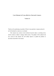
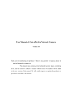
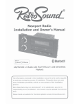
User Manual of Network Camera Version 1.0 Thank you for purchasing our product. If there is any question or request, please do not feel hesitated to contact us. This manual may contain several technically incorrect places or printing errors, and the content is subject to change without notice. The updates will be added into the new version of this manual. We will readily improve or update the products or procedures described in the manual. Security Awareness This manual contains several guidelines for all customers’ demand. Please read it carefully before operating to ensure that you can use this product correctly and safely,and to avoid the danger or material damage which may cause otherwise. Please preserve it well for future reference. The precaution measure is divided into “Warnings” and “Cautions” as below: Warnings: Serious injury or death may cause if any of the warnings is neglected. Cautions: Injury or equipment damage may cause if any of the cautions is neglected. Warnings Follow these safeguards to Cautions Follow these precautions to prevent serious injury or death. prevent potential injury or material damage. Warnings: 1. 2. 3. 4. 5. 6. Input voltage should meet both the SELV(Safety Extra Low Voltage) and the Limited Power Source with DC 12V according to the IEC60950-1 standard. If the product does not work properly, please contact your dealer or the nearest service center. Never attempt to disassemble the camera yourself. Users are responsible for any problem caused by modifying or repairing without authorization. The operating environment shall be away from rain or moisture to lower the danger of fire or shock hazard. The camera should be installed by qualified technicians, and comply with local laws and regulations. Precautions for short circuit are required for installing. Instructions for installation on walls: Please make sure that the camera can endure at least 50 Newton (N)’s pulling downward. -3- Cautions: 1. Make sure the power supply voltage is correct before using the camera. 2. Do not drop the camera or subject it to physical shock. 3. If cleaning is necessary, please use a dryer to blow the dust away from the lens and filter. Please use dry and soft cloth for outside panels cleaning. For persistent smudges, use soft cloth with a bit of cleaning agent, wipe it gently and dry it after all the above operations. Volatile solvents like ethanol, benzene and dilution agent are all forbidden, or they may damage the surface of the panels otherwise. 4. Do not aim the camera at the sun or extra bright places. A blooming or smear may occur otherwise (which is not a malfunction however), and affecting the endurance of CCD at the same time. 5. The CCD may be burned out by a laser beam, so when any laser equipment is on using, make sure that the surface of CCD will not be exposed to the laser beam. 6. Do not place the camera in extremely hot, cold(the operating temperature shall be -10℃~+60℃ ), dusty or damp locations, and do not expose it to high electromagnetism radiation. 7. To avoid heat accumulation, good ventilation is required for operating environment. 8. Keep the camera away from liquid while on using. 9. While on a delivery, the camera shall be packed in its original packing, or packing of the same texture. 10. Regular part replacement: a few parts (e.g. electrolytic capacitor) of the equipment shall be replaced regularly according to their average enduring time. The average time varies because of differences between operating environment and using history, so regular checking is recommended for all the users. Please contact with your dealer for more details. -4- INDEX CHAPTER 1 INTRODUCTION...............................................................................................................2 1.1 FUNCTIONS AND FEATURES .................................................................................................................2 1.2 APPLICATIONS .....................................................................................................................................3 CHAPTER 2 INSTALLATION.................................................................................................................4 2.1 NOTICE................................................................................................................................................4 2.2 PANELS DESCRIPTION ..........................................................................................................................4 2.2.1 SIDE ELEVATION OF THE CAMERA ....................................................................................................4 2.2.2 Rear Panel Description -----------------------------------------------------------------------------------5 2.3 HARDWARE INSTALLATION ..................................................................................................................6 2.3.1 Topological Graph of Network---------------------------------------------------------------------------6 2.3.2 Alarm Output Connection --------------------------------------------------------------------------------7 2.3.3 Pin Definition ----------------------------------------------------------------------------------------------8 2.4 INSTALLATION OF CLIENT SOFTWARE 4.0 ............................................................................................8 CHAPTER 3 PARAMETERS CONFIGURATION..............................................................................13 3.1 SET PARAMETERS THROUGH IE .........................................................................................................13 3.2 PARAMETER CONFIGURATION THROUGH CLIENT SOFTWARE .............................................................15 CHAPTER 4 WAN ACCESS...................................................................................................................22 4.1 DIAL UP WITH PPPOE.......................................................................................................................22 4.2 WAN ACCESS ....................................................................................................................................22 Q&A ..........................................................................................................................................................24 APPENDIX TECHNOLOGY SPECIFICATION ............................................................................25 1 Chapter 1 Introduction Network camera is a kind of embedded digital surveillance product that combines both the features of traditional analog camera and net DVS (Digital Video Server). Due to the embedded Linux operation system and the latest Davinci hardware platform of TI, the system operates with high scheduling efficiency. Furthermore, the firmware is burned in the flash, which makes the product small, reliable and highly stable. 1.1 Functions and Features Functions Video Encoding Techniques:Introduced H.264 video encoding standard which provides high compression ratio and flexible processing. Network Function:Support the complete TCP/IP protocols, video/alarm/audio data and IE browsing. Heartbeat Function: The server can acquire real time operating performance of the network camera through the heartbeat function. PTZ Control:Support various kinds of decoder protocols and PTZ types. Alarm:The product includes 1 channel of alarm signal input and 1 channel of alarm on/off output, and supports motion detection, video missing, mask alarm and external alarm input. Voice Talking : Support bidirectional voice talking and unidirectional voice broadcasting. User Management: Support multilevel right management. The administrator can create up to 15 separate users with different right levels, which highly improves the system security. Compression Functions The camera supports 1 channel video signal and 25fps real time H.264 stand alone hardware compression, which supports both variable bit rate and variable frame rate; besides, you can self-define both the video quality and its compressed bit rate. Support resolutions from 4CIF(PAL:704*576,NTSC:704*480), DCIF (PAL: 528*384,NTSC:528*320), 2CIF(PAL:704*288,NTSC:704*240), CIF(PAL: 352*288,NTSC:352*240) to QCIF(PAL:176*144,NTSC:176*120). Support OSD and date & time settings. Support watermark techniques. Remote Control The product offers a 10M/100M self-adaptive Ethernet interface. Support PPPoE and DHCP protocols. You can set the parameters, browse real time videos or check the camera performance through software or IE, and get external alarming or save the compressed bit rate through network. Support remote upgrades and maintenance. RS-485 supports unidirectional transparent channel function so that clients on remote PC can control the serial devices. 2 1.2 Applications This camera is ideal for remote control network applications. E.g.: ¾ Network surveillance for ATM, bank counters, supermarkets and factories. ¾ Remote surveillance for nursing homes, kindergartens and schools. ¾ AI access control systems. ¾ AI building/district management systems. ¾ Self-service systems of power plants. ¾ Outdoor monitoring systems for bridges, tunnels and crossroad traffic. ¾ Pipelining and warehouse monitoring. ¾ 24-hour monitoring for road traffic. ¾ Remote monitoring of forest and water resources. 3 Chapter 2 Installation 2.1 Notice 1. Please check if all the items on the package list have been included with your camera. 2. Read the following contents carefully before the installation. 3. Make sure that all the related equipment is power-off during the installation. 4. Check the power supply to prevent any damage caused by un-matching problems. 5. This product is not for any environment of high humidity or high temperature. Conditions of rain, airlessness or frequent shaking are also prohibited. 6. If the product does not operate properly, please contact your dealer or the nearest service center. Never attempt to disassemble the camera yourself. Users are responsible for any problem caused by modification or repairing without authorization. 【Notice】Power supply, lens and SD card are optional. 【Notice】The lens should be CS mount and its mass should be less than 1kg, and the prominent part behind the mount surface should be less than 5mm. 【Notice】Please use a C mount adaptor for C mount lens. 2.2 Panels Description 2.2.1 Side Elevation of the Camera Fig 2.2.1 Side Elevation of the Camera 4 【Notice】The and marks in the camera stand for electronic PTZ and 2000,000 pixels resolution. 2.2.2 Rear Panel Description Fig. 2.2.2 Rear Panel Rear panel interfaces descriptions (from left to right and top to bottom): 1. Standard BNC for Ethernet (LAN) RJ45 (10M/100M self-adaptive). 2. 1 channel voice talk input (AUDIO IN),3.5mm audio interface, 2.0~2.4Vp-p, 1kΩ. 3. 1 channel voice talk output (AUDIO OUT), 3.5mm audio interface, electric line level, 600Ω. 4. Power indicator lamp (POWER). 5. Power supply (DC12V). Please refer to the appendix for detailed specification, and always remember to use a matched regulator. 6. 1 channel alarm output (1A 1B). Please refer to Section 2.3.2 for pin definition. (The external series-wound power shall be under 12V DC/ 30mA.) 7. 1 channel alarm input (IN G) with 0-12V DC signal. 8. RS-485 bus interface (T+ T-). 9. BLC: Automatically adjust the exposure for back light compensation while on function. AI: Switch the mode to AI for auto iris mode. Auto Electronic Shutter(AES): Switch the mode to AES if auto iris mode is not needed. 10. Auto iris switch(VD DD): Switch the mode to VD for video drive iris lens while DD for DC drive iris lens. 11. SD card slot (SD). 12. Standard BNC for 1 channel video output (VIDEO OUT). 5 【Notice】The 9th,10th and 12th functions are not incorporated in DS-2CD832F and DS-2CD852F cameras. 2.3 Hardware Installation 2.3.1 Topological Graph of Network Fig.2.3.1 Topological Graph of Network 6 Physical Interface Connection Connect to network devices, such as switch , HUB, etc. Please refer to Appendix B for pin Definition. Audio Input Connect to audio input devices such as active tone (2.0~ (AUDIO IN) 2.4Vp-p, 1kΩ) Audio Output Connect to sounders like loudhailer. (AUDIO OUT) Power Supply Please refer to the appendix for specified types. Please use (DC12V) a matched regulator. 1 channel alarm out. Please refer to Section 2.3.2 for Alarm Output connecting instructions. (external series-wound power (1A 1B) shall be under 12V DC / 30mA) LAN Interface Alarm Input(IN 1 channel alarm in. G) RS-485 Interface Connect to RS-485 devices like PTZ. (T+ T-) SD card slot Insert an SD card for local storage. Video Output Standard BNC, connect to monitor. (VIDEO OUT) 2.3.2 Alarm Output Connection Description of Alarm Output Connection The alarm output is a on/off output that requires external power supply on connection. The external power supply shall be 12V DC/30mA, or use AC with 7 external relays. Equipment damage or electric shock may cause if without relays. 2.3.3 Pin Definition (1)LAN between the network port of camera and HUB (Direct Cable) (2)LAN between the network port of camera and PC (Cross Cable): 2.4 Installation of Client software 4.0 【Notice】Your PC display adaptor shall support color-space conversion and zooming .Display adaptors like Nvidia Tnt/Tnt2、Geforce Mx 200/400/420/440 Fx5200/5600, ATI Radeon 7000/7200/7500/8500 /9000/9200 /9500/9600, MatroxG450/550, INTEL845G/865G are already tested. Be aware that the display adaptor drivers should support BLT. Step1: Double click “Client software (v4.0)” under Windows Operating System. The “Preparing Setup” dialog box will pop up as Fig.2.4.1 and goes to Fig2.4.2 automatically. 8 Fig.2.4.1 Client Software Installation Fig.2.4.2 License Agreement Step2: Enable the option “I accept the terms of the license agreement” and click the “Next” button to go to the next step as Fig.2.4.3. 9 Fig.2.4.3 Customer Information Step3: Input “User Name”, “Company Name” and click “Next” to go to the next step. Fig.2.4.4 Destination Folder Step4: Select the destination folder and click “Next” to go to the next step. 10 Fig2.5.5 Ready to Install the Program Step5: Click “Install” to start installation shown as Fig2.6.6. Fig2.6.6 Install Process Step6: After finishing the installation, the installation completed dialog box will popup as Fig.2.7.7. 11 Fig2.7.7 Installation Complete Click the “Finish” button to close the dialog box. After the client software has been installed, you can find the remote client software through “Start” -> “Program” on your PC. 12 Chapter 3 Parameters Configuration There are several network parameters of the camera that need to be set after the hardware installation. Those parameters including IP address, subnet mask and port number, etc. can be set through various kinds of methods, 2 of which are introduced as below. 1. Set the camera parameters such as IP address and PPPOE through IE. 2. Set the camera parameters through the client software. Please make sure that the PC and network camera are connected and can ping successfully before the parameter setting. 2 different ways of connections are showed as Fig. 3.1 & Fig. 3.2. Fig.3.1 Direct Line Connection Fig.3.2 Cross Line Connection 3.1 Set Parameters through IE The default IP of the camera is 192.0.0.64 with 8000 as the default port, admin as the administrator, and 12345 as the password. The administrator can create up to 15 separate operators with different right levels. To login the camera through IE, input the IP address in the address column, and the “Login” dialog box will pop-up as Fig. 3.3. Input your user name and password, and then click “Login” to enter the “preview” page. Double click the “Camera 01” channel or “Preview” button to view the menu as Figure 3.4. Right click the “Camera 01” channel, and the “Main Stream”、“Sub Stream” and “Open sound” options will popup. Select the Open sound option. 13 Fig. 3.3 Login Interface Fig. 3.4 Previewing Interface The “Playback” and “Log” functions are reserved as Fig. 3.4. To set the camera parameters through IE browser, click “Config” and wait for the “Remote Parameters Config” dialog box to pop up, and then set the parameters like IP address, etc. for your demand as Fig. 3.5. For more specific information of “Remote Parameters Config”, please refer to “Instructions of Client Software (version 4.0)” from Section 2.5.3 of remote-distance parameter settings. Instructions can be found in the client software4.0 in the path of 14 “Start” → “Program”→ “client software 4.0” after installation. Fig. 3.5 Remote Parameters Config 【Notice】 Security level settings are necessary for browsing equipments by IE. Please open the IE browser and set the security level to “Low” in “Tools/ Internet Options/ Security/ Customize” or enable the “ActiveX Controls and Plug-Ins” directly. 3.2 Parameter Configuration through Client Software After the installation of client software 4.0, click the “client software 4.0 ”in “Start”→ “Program”→ “client software 4.0”, a message box of “Register Administrator” as Fig. 3.6 will appear by then for the first time running. Both the user name and password should be no less than 6 digits for registration. 【Notice】 Please keep the user name and password in mind .You may not be able to get access to the software if any of them is missing. 15 Fig.3.6 Register Administrator Enter the registered user name and password as Fig. 3.7. Click “Login” to enter the “Preview” menu as Fig. 3.8. Fig. 3.7 User Login Fig. 3.8 Preview Menu Click the “Configure” button in Fig. 3.8, and then right click the blank spaces in 16 the middle. Click the “Create Root Node” button as Fig. 3.9, and the “Area Properties” message will pop up as fig 3.10. Fig. 3.9 Create Root Node Fig. 3.10 Area Properties 17 Input the area name (you can create whatever name you like) and click “OK” as Fig. 3.11. Then right click the area name you have just created as Fig. 3.12. Fig. 3.11Area Name Adding Completed Fig. 3.12 Right Click the Area Name 18 Click “Add Device”, and the “Server Properties” dialog box will pop up as Fig. 3.13. Input your “Server Name” and select “HC” from the “Server Type” option. Select “Normal” from “Register” option. Input your camera IP in “Server IP”, e.g. 192.0.0.64; “User Name”: admin, “Password”: 12345, and 8000 for the default “Port”, and then modify “Channel” to 1. Click the “OK” button as Fig. 3.14. Fig. 3.13 Add Device 19 Fig.3.14 DVR Adding Completed Click the “Preview” button in Fig. 3.14 to enter the “Preview” menu as Fig. 3.15. Double click the channel name in the left tree to preview the pictures. Double click the channel Fig.3.15 Preview Menu 20 Please refer to “Network Video Surveillance Software Operation Instruction (4.0)” for more detailed parameters configuration. You can find the document in PC Operating System after the installation of client software 4.0 by selecting “Start”-> “Program”-> “client software 4.0”. 21 Chapter 4 WAN Access The IP protocol supports WAN access based on PPPoE dial up function. Make sure that the software you are using supports the function before using these network functions. 4.1 Dial Up With PPPoE Make sure that the user name and pass word of PPPoE are set correctly by the client software (refer to “User Manual of Network Digital Surveillance Software”) as Fig.4.1. The camera will try to establish connection to the network with PPPoE function automatically every time when it is powered on, and get a dynamic IP address by then. Fig.4.1 Dial Up with PPPoE 【Notice】Please make sure that the ADSL Modem is powered on .The camera needs to be restarted to establish the network connection after the configuration of PPPoE parameters for the first time. 4.2 WAN Access There are two methods to get the access, which are shown as below. 1. Get a static IP from your ISP for WAN access. You can open some ports (such as 80 & 8000 ports) in the router which has got static IP from the ISP, and then connect them to the router. After that you can use the client software to control it. Turn to ch3.2 to find the client software operations. 2. Use DNS service for WAN access. You will need a PC connected to Internet with static IP that owns software 22 providing DNS service at the same time(such as IP Server)(the PC is so-called DNS server).You can also register a domain name through the DNS service dealer and visit it with the domain name. When network camera is connected to WAN with PPPoE, it will get an IP address, and send its name and the IP to the DNS server. The client software will immediately connect to the PC that used as the DNS server to tell it which network camera is waiting for access. Then the server will search for all the registered network cameras, and match the camera with this IP. When the IP address is returned, the client software will connect to the network camera to get the video. Operations: Run the client software 4.0, select “Configure”Æ “Server Configuration” select network camera. In the right tree, input “Server Name” & “DNS Host IP” in the “Server Configuration” box as Fig 4.1, and click “Confirm”. Select “Configure”-> “Device Management”, double click the network camera name you just added, the “server attribute” message box will pop up as Fig. 4.2. Make sure that the “sever name” is consist with the sever name in “remote config”; and select “private DNS” in “register mode”; then input the IP address of DNS server in “DNS address”, click “Confirm”. Then you can preview the picture in the “preview” menu. Fig.4.2 DNS Server 23 Q&A 1、Time showing incorrectness: Use client 4.0 to correct the time by selecting “configure”Æ“local configure”Æ“Hard disk recorder timing” 2、IP unknowing: Connect the camera and PC with the same hub,turn on the camera and run the “SADP Search Software” on PC to get the IP of the connected camera. You can get the SADP from your dealer. 3、Administrator password missing: Please contact your dealer. Please contact your dealer if any of the above information cannot meet your demand. If any of the above information cannot meet your demand, please contact your dealer. 24 Appendix Technology Specification Table 1 Type Parameter DS-2CD802PF/8 02NF Sensor Lens interface Video standard Resolution Minimum illumination Automatic aperture Lens Power supply SD card Maximum resolution Frame rate 1/3"SONY Super HAD CCD C/CS mount PAL/NTSC 420 TV lines 480 TV lines 535 TV lines 0.1Lux @ F1.2(0 0.2Lux @ F1.2(0 0.1Lux @ F1.2(0 LUX with IR) LUX with IR) LUX with IR) DC/VIDEO optional optional optional 704 x 576/PAL,704 x 480/NTSC 25frame/PAL,30frame/NTSC 1ch,3.5mm audio interface, electric line level: 2.0~2.4Vp-p, impedance:1kΩ 1c,3.5mm audio interface, electric line level, impedance:600Ω Audio input Audio output Video compression standard Video compression rate Motion detection Dual stream Local storage of SD card Heartbeat Password protection Support protocol Communication interface Alarm in Alarm out Working temperature Power supply Power consumption Dimensions (mm) Weight DS-2CD812PF/812 DS-2CD892PF/892 NF NF H.264 32 K~2M,custom(8M/bps maximum) support support support support support TCP/IP,HTTP,RTP,RTCP,ARP,ICMP,PPPOE,DHCP,FTP,UDP, DNS,DDNS,SMTP,NTP,Static IP One RJ45 10M/100M self-adapt Ethernet pot and one RS- 485 interface 1,0~12V DC 1,on-off -10℃--60℃ 12V DC 5W MAX 65*67*122 600g 25 Table 2 Type Parameter Sensor Camera interface Video standard Resolution Minimum illumination Auto iris Lens Power supply SD card Maximum resolution Frame rate Audio input Audio output Video compression standard Video compression rate Motion detection Dual stream Local storage of SD card Heartbeat Password protection Protocol support Communication interface Alarm in Alarm out Working temperature Power supply Power consumption Dimensions(mm) Weight DS-2CD832F DS-2CD852F 1/4 inch CMOS 1/3 inch CMOS C/CS mount —— 640x480 Pixels(VGA) 1600x1200 Pixels(UXGA) 0.4Lux 2Lux —— optional optional optional 704 x 576/PAL,704 x 1600x1200 480/NTSC 25 frame/PAL,30 25 frame(704x576),5 frame/NTSC frame(1600x1200) 1channel 3.5mm audio interface(electric line level : 2.0~ 2.4Vp-p, 1kΩ) 1channel 3.5mm audio interface(electric line level, 600Ω) H.264 32 K~2M,customization (8M/bps maximum) support support support support support TCP/IP,HTTP,RTP,RTCP,ARP,ICMP,PPPOE,DHCP,FTP,UD P,DNS,DDNS,SMTP,NTP, and Static IP One RJ45 10M/100M self-adapted Ethernet port and one RS -485 interface 1, 0~12V DC 1,on-off -10℃--60℃ 12V DC 5W MAX 65*67*122 600g 26