1
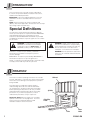
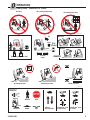
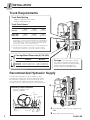
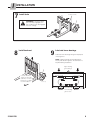
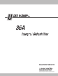
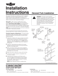
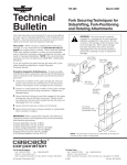
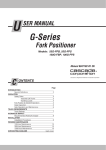
U SER MANUAL F-Series Sideshifter C ONTENTS INTRODUCTION Special Definitions OPERATION Safety Rules Industrial Lift Trucks Handling Loads Sideshifter Operation Safe Operation and Maintenance OSHA Regulations INSTALLATION Truck Requirements Recommended Hydraulic Supply Installation Procedure PERIODIC MAINTENANCE Daily thru 2000-Hour Maintenance PARTS Recommended Spare Parts Publications Page 1 2 2 3 3 4 4 5 5 6 8 9 9 Manual Number 219941-R8 cascade corporation Cascade is a Registered Trademark of Cascade Corporation I NTRODUCTION This user manual is for Cascade F-Series Sideshifters. It contains an Operation Guide, Installation Instructions, and Recommended Spare Parts. IMPORTANT: All hosing and flared fittings on F-Series Sideshifters are JIC as standard, with face seal as an option. NOTE: All specifications are shown in Imperial and (Metric) units where applicable. All fasteners have a torque value range ±10% of stated value. Special Definitions The statements shown appear throughout this Manual where special emphasis is required. Read all WARNINGS and CAUTIONS before proceeding with any work. Statements labeled IMPORTANT and NOTE are provided as additional information of special significance or to make the job easier. WARNING: Rated capacity of the truck/ attachment combination is a responsibility of the original truck manufacturer and may be less than shown on the attachment nameplate. Consult the truck nameplate. WARNING – A statement preceded by WARNING is information that should be acted upon to prevent bodily injury. A WARNING is always inside a ruled box. WARNING: Do not operate this attachment unless you are a trained and authorized lift truck driver. CAUTION – A statement preceded by CAUTION is information that should be acted upon to prevent machine damage. IMPORTANT – A statement preceded by IMPORTANT is information that possesses special significance. NOTE – A statement preceded by NOTE is information that is handy to know and may make the job easier. O PERATION Backrest This Section contains operating instructions for Cascade F-Series Sideshifters. It will help you avoid common errors which often cause damage to the equipment or product being handled. This information is intended to simplify operator understanding about effective and safe Sideshifter use and operation. Read this information thoroughly before operating the Attachment. Be sure you know and understand all operating procedures and safety precautions. If you have any questions, or don’t understand a procedure, ask your supervisor. Emphasize Safety! Most accidents are caused by operator carelessness or misjudgement. You must watch for poorly maintained equipment and hazardous situations and correct them. Upper Hooks Cylinder Sideshifter Frame SS0159.eps 1 Forks Lower Hooks 219941-R8 O PERATION Safety Rules – Industrial Lift Trucks No reaching through mast No riders No standing under load GA0047.eps With load Tilt Raise 3 in. (8 cm) No load P P Traveling empty Motor off, park, lower load RAMPS P No turning on ramp No parking on ramp Watch clearances GA0048.eps TRAFFIC STOP Observe Wet floors 219941-R8 Workers Stops Bumps Dips Slow for two-way traffic Sound horn, slow at intersection Sound horn, slow at corner 2 O PERATION Safety Rules – Handling Loads Top of load should not extend above backrest. Limit sideshifting with raised load. CAUTION: Do not put side loads on forks. LOAD WEIGHT Center load prior to traveling. Limit truck movement with raised load. FP0017.eps Load weight must not exceed combined truck/attachment capacity (see truck nameplate). Raise load prior to sideshifting. Total fork capacity (LH + RH fork) must be greater than load weight. Check capacity stamp on forks. Sideshifter Operation AUXILIARY VALVE FUNCTIONS SIDESHIFTING A Sideshift Left B Sideshift Right Hoist down Tilt forward A B A B GA0010.eps Hoist up Tilt Back 3 SS0160.eps 219941-R8 S AFE OPERATION AND MAINTENANCE OSHA Regulations – Industrial Trucks and Attachments (Specific Regulations from OSHA 1910.178) WARNING: The safe operation and maintenance of industrial trucks is regulated by Occupational Safety and Health (OSHA) regulations 1910.178 and American National Standards Institute (ANSI) Safety Standard for Powered Industrial Trucks, ANSI B56.1. When operating and maintaining industrial trucks equipped with attachments you should pay particular attention to the following sections of these regulations. You should be familiar with all sections of these regulations. Ask your employer for the complete regulations. (6) A safe distance shall be maintained from the edge of ramps or platforms while on any elevated dock or platform or freight car. Trucks shall not be used for opening or closing freight doors. (10) A load backrest extension shall be used whenever necessary to minimize the possibility of the load or part of it from falling rearward. (n) Traveling (4) The driver shall be required to slow down and sound the horn at cross isles and other locations where vision is obstructed. If the load being carried obstructs forward view, the driver shall be required to travel with the load trailing. (7i) When ascending or descending grades in excess of 10 percent, loaded trucks shall be driven with the load upgrade. (a) General Requirement (4) Modifications and additions which affect capacity and safe operation shall not be performed by the customer or user without manufacturers prior written approval. Capacity, operation and maintenance instruction plates, tags or decals shall be changed accordingly. (5) If the truck is equipped with front-end attachments other than factory installed attachments, the user shall request that the truck be marked to identify the attachments and show the appropriate weight of the truck and attachment combination at maximum elevation with load laterally centered. (6) The user shall see that all nameplates and markings are in place and maintained in a legible condition. (e) Safety Guards (2) If the type of load presents a hazard, the user shall equip fork trucks with a vertical load backrest extension in accordance with (a)(2) following. (a)(2) All new powered industrial trucks acquired and used by an employer after February 15, 1972 shall meet the design and construction requirements for powered industrial trucks established in the “American National Standard for Powered Industrial Trucks, Part II, ANSI B56.1”, except for vehicles intended primarily for earth moving or over-the-road hauling. (7iii) On all grades the load and load engaging means shall be tilted back if applicable, and raised only as far as necessary to clear the road surface. (o) Loading (1) Only stable or safely arranged loads shall be handled. Caution shall be exercised when handling off-center loads which cannot be centered. (2) Only loads within the rated capacity of the truck shall be handled. (3) The long or high (including multiple-tiered) loads which may affect capacity shall be adjusted. (4) Trucks equipped with attachments shall be operated as partially loaded trucks when not handling a load. (5) A load engaging means shall be placed under the load as far as possible; the mast shall be carefully tilted backward to stabilize the load. (6) Extreme care shall be used when tilting the load forward or backward, particularly when high tiering. Tilting forward with load engaging means elevated shall be prohibited except to pick up a load. An elevated load shall not be tilted forward except when the load is in a deposit position over a rack or stack. When stacking or tiering, only enough backward tilt to stabilize the load shall be used. (l) Operator Training Only trained and authorized operators shall be permitted to operate a powered industrial truck. Methods shall be devised to train operators in the safe operation of powered industrial trucks. (p) Operation of the Truck (m) Truck Operations (1) Trucks shall not be driven up to anyone standing in front of a bench or other fixed object. (2) No person shall be allowed to stand or pass under the elevated portion of any truck, whether loaded or empty. (1) If at any time a powered industrial truck is found to be in need of repair, defective, or in any way unsafe, the truck shall be taken out of service until it has been restored to safe operating condition. (q) Maintenance of Industrial Trucks (1) Any power-operated industrial truck not in safe operating condition shall be removed from service. All repairs shall be made by authorized personnel. (3) Unauthorized personnel shall not be permitted to ride on powered industrial trucks. A safe place to ride shall be provided where riding of trucks is authorized. (4) The employer shall prohibit arms or legs from being placed between the uprights of the mast or outside the running lines of the truck. (5) All parts of any such industrial truck requiring replacement shall be replaced only by parts equivalent as to safety with those used in the original design. (5i) When a powered industrial truck is left unattended, load engaging means shall be fully lowered, controls shall be neutralized, power shall be shut off and brakes set. Wheels shall be blocked if the truck is parked on an incline. (6) Industrial trucks shall not be altered so that the relative positions of the various parts are different from what they were when originally received from the manufacturer, nor shall they be altered either by the addition of extra parts not provided by the manufacturer or by the elimination of any parts. Additional counter weighting of fork trucks shall not be done unless approved by the truck manufacturer. (5ii) A powered industrial truck is unattended when the operator is 25 feet or more away from the vehicle which remains in his view, or whenever the operator leaves the vehicle and it is not in his view. (5iii) When the operator of an industrial truck is dismounted and within 25 feet of the truck still in his view, the load engaging means shall be fully lowered, controls neutralized and the brakes set to prevent movement. (7) Industrial trucks shall be examined before being placed in service and shall not be placed in service if the examination shows any condition adversely affecting the safety of the vehicle. Such examinations shall be made at least daily. When industrial trucks are used on a round-the-clock basis, they shall be examined after each shift. Defects when found shall be immediately reported and corrected. 219941-R8 4 I NSTALLATION Truck Requirements Truck Relief Setting 2000 psi (140 bar) Recommended 3500 psi (240 bar) Maximum Truck Flow Volume ➀ Min. ➁ Recommended Max. ➂ 55F, 65F 1 GPM (4 L/min.) 2 GPM (7.5 L/min.) 3 GPM (12 L/min.) 100F, 120F, 150F, 165F 1 GPM (4 L/min.) 4 GPM (16 L/min.) 5 GPM (20 L/min.) ➀ Cascade F-Series Sideshifters are compatible with SAE 10W petroleum base hydraulic fluid meeting Mil. Spec. MIL-0-5606 or MIL-0-2104B. Use of synthetic or aqueous base hydraulic fluid is not recommended. If fire resistant hydraulic fluid is required, special seals must be used. Contact Cascade. ➁ Flow less than recommended will result in a slow sideshift speed. ➂ Flow greater than maximum can result in excessive heating, reduced system performance and short hydraulic system life. GA0095.eps Carriage Mount Dimension (A) ITA (ISO) A Class II Class III Class IV Minimum Maximum 14.94 in. (380.0 mm) 18.68 in. (474.5 mm) 23.44 in. (595.5 mm) 15.00 in. (381.0 mm) 18.74 in. (476.0 mm) 23.50 in. (597.0 mm) Carriage – Clean and inspect carriage bars. Make sure that bars are parallel and ends are flush. Grind smooth any protruding welds that may affect Sideshifter lower bearings. Repair any damaged notches. GA0028.eps Recommended Hydraulic Supply The Sideshifter will require one of the hydraulic supply arrangements shown below. All hoses and fittings should be at least No. 4 with 3/16 in. (5 mm) minimum I.D. Refer to Cascade Hose & Cable Reel Selection Guide, Part No. 212199 to select the correct hose reel for the mast and truck. A Auxiliary Valve Functions Check for compliance with ITA (ISO) standards: B Tilt Forward Hoist Down Sideshift Left GA0026.eps A GA0094.eps 5 Hoist Up Tilt Sideshift Back Right B RH THINLINE 2-Port Hose Reel Supply Group OR Mast Single Internal Hose Reeving 219941-R8 I 1 NSTALLATION Attach overhead hoist Lifting Eye OR Eye Bolts Stamped Capacity, Weight, Load Center, HCG information Stamped Model, Serial Number, Date Code Sticker showing Patents, Service Phone Numbers WARNING: Check the attachment weight (located on the nameplate) to make sure the overhead hoist and chains or straps are at least the rated capacity of the attachment. SS0918.eps 2 Remove bolt-on lower hooks SS1062.eps SS1063.eps Two Capscrew Hooks 3 Four Capscrew Hooks Mount Sideshifter on truck carriage ITA Class II – .60-.66 in. (15-17 mm) ITA Class III – .72-.78 in. (18-20 mm) ITA Class IV – .72-.78 in. (18-20 mm) Engage locator tab with center notch ITA Class II – .32–.36 in. (8-9 mm) ITA Class III – .39–.43 in. (10-11 mm) ITA Class IV – .47–.51 in. (12-13 mm) Truck Upper Carriage Bar 219941-R8 SS0152.eps 6 I 4 NSTALLATION Install lower hooks BOLT-ON HOOKS – Four Capscrew BOLT-ON HOOKS – Two Capscrew Truck Lower Carriage Bar Iron Hook Clearance: .04 in. (1 mm) Min. .08 in. (2 mm) Max. Bronze Hook Clearance: 0 Clearance, touching but not tight. Sideshifter Frame Truck Lower Carriage Bar Sideshifter Frame Bearing Clearance: .04 in. (1 mm) Min. .08 in. (2 mm) Max. SS1060.eps SS1061.eps Shim to adjust clearance Tighten capscrews to: Class II/III – 120 ft.-lbs. (165 Nm) Class IV – 235 ft.-lbs. (320 Nm) Tighten capscrews to: Class II – 65 ft.-lbs. (90 Nm) NOTE: If frame is equipped with a hydraulic component guard, remove the guard to access shims located on the lower fork bar. QUICK-DISCONNECT HOOKS Reverse guides to reduce hook-to-carriage clearance. Clearance: .04 in. (1 mm) Min. .08 in. (2 mm) Max. 5 Offset on top provides max. clearance: Class II/III – .62 in. (16 mm) Class IV – .83 in. (21 mm) 6 Flush supply hoses SS1059.eps Tighten capscrews to: Class II/III – 120 ft.-lbs. (165 Nm) Class IV – 190 ft.-lbs. (250 Nm) Install hoses Optional Installation Kit 205826 shown for internal reeving. GA0046.eps Back (Driver's) View SS0154.eps 7 219941-R8 I NSTALLATION 7 Install forks Fork Lock Pins WARNING: If the fork locking pin is not fully engaged, the fork could become disengaged from the carriage. SS0914.eps 8 9 Install backrest Lubricate lower bearings Lubricate lower bearings with general-purpose chassis grease. NOTE: Upper bearings are prelubed at the Factory with break-in grease. No lubrication is required during installation. Upper bearing grease fittings Cascade Backrest– Tighten to 145 ft.-lbs. (195 Nm). For other backrests, see OEM recommendations. SS0156.eps SS0157.eps Lower bearing grease areas 219941-R8 8 P ERIODIC MAINTENANCE Daily WARNING: After completing any service procedure, always test the sideshifter through five complete cycles. First test with no load, then test with a load to make sure the attachment operates correctly before returning it to the job. Check items shown each day. Report problems to your supervisor. See Service Manual for troubleshooting, maintenance and repair procedures. WARNING: If the fork locking pin is not fully engaged, the fork could become disengaged from the carriage. 100-Hour Every time the lift truck is serviced or every 100 hours of truck operation, complete the following maintenance procedures: Backrest Fork Stops Fork Lock Pins Cylinder and hoses for leaks Upper and lower hook engagement • Check for loose or missing bolts, worn or damaged hoses, hydraulic leaks, and damaged or missing fork stops. • Inspect lower hooks for wear and proper clearance. Adjust if necessary, refer to Installation, step 4 . Tighten lower hook capscrews to: Forks Two Capscrew Hooks Class II/III – 120 ft.-lbs (165 Nm) Class IV – 235 ft.-lbs (320 Nm) Four Capscrew Hooks Class II – 65 ft.-lbs (90 Nm) SS0915.eps Fasteners 300-Hour After each 300 hours of truck operation, in addition to the 100-hour maintenance, perform the following procedures: • Tighten backrest capscrews (Cascade) to 145 ft.-lbs. (195 Nm). • Apply general-purpose chassis grease to Sideshifter upper and lower bearings. 1000-Hour After each 1000 hours of truck operation, in addition to the 100 and 300-hour maintenance, perform the following procedures: • Inspect upper and lower bearings for wear. If any bearing is worn to less than .09 in. (2.5 mm) thickness, replace the entire bearing set. Refer to service manual for replacement procedure. 2000-Hour 2000-Hour (Continued) Inspect for the following defects: • Surface cracks • Straightness of blade and shank • Fork angle • Difference in height of fork tips • Positioning lock • Wear on fork blade and shank • Wear on fork hooks • Legibility of marking NOTE: Fork Safety Kit 3014162 contains wear calipers, inspection sheets and safety poster. Also available is fork hook & carriage wear gauge 209560 (Class II), 209561 (Class III) and 6105257 (Class IV). After 2000 hours of truck operation, in addition to the 100, 300 and 1000-hour maintenance, forks in use shall be inspected at intervals of not more than 12 months (for single shift operations) or whenever any defect or permanent deformation is detected. Severe applications will require more frequent inspection. Fork inspection shall be carried out by trained personnel to detect any damage that might impair safe use. Any fork that is defective shall be removed from service. Reference ANSI B56.1-2005. 9 219941-R8 P ARTS Recommended Spare Parts 55F 65F 100F 120F, 150F, 165F PART NO. PART NO. PART NO. PART NO. 6020486 ◆ 6051249 6051249 6079936 UNITS SERVICED DESCRIPTION 1-5 6-19 20-50 QTY. QTY. QTY. 8 16 32 Upper Bearing–Composite 6033486 ◆ 6052405 6052405 6082297 Upper Bearing–Bronze 4 8 16 6033487 ◆ 6057162 6057162 6057162 Lower Bearing–Composite 6 12 24 226842 ◆ 6058041 6058041 6058041 Lower Bearing–Bronze 4 8 16 204186 204186 204186 6083157 6818778 ––– ––– ––– Lower Hook 0 2 4 Lower Hook ● 0 2 4 6818788 ––– ––– ––– Lower Hook Bearing–Bronze ● 4 8 16 6818771 ––– ––– ––– Lower Hook Bearing Shim ● 6 12 24 206174 ––– ––– ––– Capscrew, M12 x 45 ● 0 8 16 752903 752903 752903 ––– Capscrew, M16 x 45 0 4 8 ––– ––– ––– 768580 Capscrew, M20 x 60 0 4 8 678990 678990 678990 ––– Nut, M16 0 4 8 ––– ––– ––– 783800 Nut, M20 0 4 8 667225 667225 667225 215419 Washer 0 4 8 681473 ––– ––– ––– Lockwasher, M12 ● 0 8 16 ■ ■ ■ ■ Cylinder Assembly 0 0 1 219868 219868 564409 564409 Cylinder Service Kit 1 2 4 ◆ Kit containing two each of two different style bearings. Match the bearing being replaced. ■ Refer to part number stamped on part or supply serial number stamped on sideshifter frame when purchasing parts. ● Four Capscrew Hook applications. Publications Tool Catalog 673964 Literature Order Form AN U 679929 AR TS M Service Manual G 220526 S I Service Literature Index and Order Form Ordering Information – Parts, Service and Operator Guide literature is sold through the Cascade Parts Depot. All dealerships with an open account, please indicate quantity desired and purchase order number. All others please enclose a check payable to Cascade Corporation. FAX: 513-325-9270 Mail: Cascade Corporation P.O. Box 360 Springfield, Ohio 45501 Phone: 513-322-1199 Master Service Manual – Part No. 673969 Includes all Service manuals listed in a 3-ring binder for $140.00. P User Manual ER N IN A TIO ALL NST O PERATOR’S GUIDE T 219941 AL DESCRIPTION OOL CATA LO PART NO. C VI cascade STR AL NU A EM cascade corporation GA0377.eps 219941-R8 10 Do you have questions you need answered right now? Call your nearest Cascade Service Department. Visit us online at www.cascorp.com AMERICAS Cascade Corporation U.S. Headquarters 2201 NE 201st Fairview, OR 97024-9718 Tel: 800-CASCADE (227-2233) Fax: 888-329-8207 Cascade do Brasil Rua João Guerra, 134 Macuco, Santos - SP Brasil 11015-130 Tel: 55-13-2105-8800 Fax: 55-13-2105-8899 Cascade Canada Inc. 5570 Timberlea Blvd. Mississauga, Ontario Canada L4W-4M6 Tel: 905-629-7777 Fax: 905-629-7785 EUROPE-AFRICA Cascade Italia S.R.L. European Headquarters Via Dell’Artigianato 1 37030 Vago di Lavagno (VR) Italy Tel: 39-045-8989111 Fax: 39-045-8989160 Cascade (Africa) Pty. Ltd. PO Box 625, Isando 1600 60A Steel Road Sparton, Kempton Park South Africa Tel: 27-11-975-9240 Fax: 27-11-394-1147 ASIA-PACIFIC Cascade Japan Ltd. 2-23, 2-Chome, Kukuchi Nishimachi Amagasaki, Hyogo Japan, 661-0978 Tel: 81-6-6420-9771 Fax: 81-6-6420-9777 Cascade Korea 121B 9L Namdong Ind. Complex, 691-8 Gojan-Dong Namdong-Ku Inchon, Korea Tel: +82-32-821-2051 Fax: +82-32-821-2055 Cascade-Xiamen No. 668 Yangguang Rd. Xinyang Industrial Zone Haicang, Xiamen City Fujian Province P.R. China 361026 Tel: 86-592-651-2500 Fax: 86-592-651-2571 Cascade Australia Pty. Ltd. 1445 Ipswich Road Rocklea, QLD 4107 Australia Tel: 1-800-227-223 Fax: +61 7 3373-7333 Cascade New Zealand 15 Ra Ora Drive East Tamaki, Auckland New Zealand Tel: +64-9-273-9136 Fax: +64-9-273-9137 Sunstream Industries Pte. Ltd. 18 Tuas South Street 5 Singapore 637796 Tel: +65-6795-7555 Fax: +65-6863-1368 Cascade India Material Handling Private Limited No 34, Global Trade Centre 1/1 Rambaugh Colony Lal Bahadur Shastri Road, Navi Peth, Pune 411 030 (Maharashtra) India Phone: +91 020 2432 5490 Fax: +91 020 2433 0881 c © Cascade Corporation 2012 04-2012 Part Number 219941-R8