1
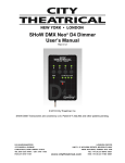
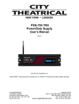
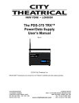
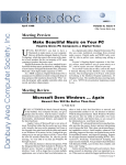
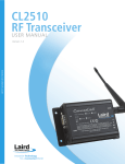
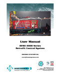
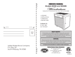
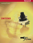
The SHoW DMX™
OEM Receiver
User’s Manual
Rev 1.2
© 2008 City Theatrical, Inc.
Patent Pending
The SHoW DMX OEM Receiver User’s Manual
Contents
Figures .............................................................................................................................. 3
Revision History ................................................................................................................ 3
Radio Compliance Information.......................................................................................... 4
5692 SHoW DMX Radio CE Declaration of Conformity ................................................ 7
System Compliance Information ....................................................................................... 8
Safety Notices ................................................................................................................... 8
End-Use Compliance Certifications .................................................................................. 8
Markings............................................................................................................................ 9
Installing the SHoW DMX OEM Receivers ..................................................................... 12
Typical Installation notes ............................................................................................. 12
Power requirements .................................................................................................... 12
Mounting Steps............................................................................................................ 13
Connections .................................................................................................................... 14
Hardware Configuration .................................................................................................. 14
Operating the SHoW DMX OEM Receiver...................................................................... 14
Controls and Features ................................................................................................. 15
Operation and Configuration ....................................................................................... 15
SHoW ID: ................................................................................................................ 16
Power ...................................................................................................................... 17
Software .................................................................................................................. 17
Certification ............................................................................................................. 17
Advanced OEM applications ........................................................................................... 17
Control and configuration via host user interface ........................................................ 17
Extension User Interface ............................................................................................. 18
DMX System Flow ....................................................................................................... 19
RDM System Flow....................................................................................................... 20
Frequency Hopping Spread Spectrum (FHSS) Radio Technology................................. 20
The Advanced Wireless DMX Broadcast Features of SHoW DMX ................................ 21
A Custom-Built Radio .................................................................................................. 21
Optimized High-Speed Wireless Data Transmission................................................... 21
DMX Synchronized Hopping ....................................................................................... 21
Refresh Rate Compensation ....................................................................................... 21
Adjustable Output Power............................................................................................. 22
Full Bandwidth Hopping............................................................................................... 22
Limited Bandwidth Hopping......................................................................................... 22
Limited Burst DMX Output........................................................................................... 22
Appendix A, SHoW DMX Model Summary ..................................................................... 24
Appendix B, SHoW DMX OEM Unit Part Numbers......................................................... 26
Remote User Interface Part Number Generation:........................................................... 26
Optional accessories not included with an OEM:............................................................ 26
Rev 1.1 10/14/08
2 of 27 Pages
The SHoW DMX OEM Receiver User’s Manual
Figures
Figure 1, Required Label for 5691 Radio, 5605 Receiver, 5607 Transmitter.................... 9
Figure 2, required Label for 5692 Radio, 5606 Receiver, 5608 Transmitter ..................... 9
Figure 3, OEM Unit Specifications .................................................................................. 11
Figure 4, OEM Unit Dimensions and Mounting Holes..................................................... 11
Figure 5, SHoW DMX OEM Unit ..................................................................................... 12
Figure 6, SHoW DMX OEM Wiring ................................................................................. 13
Figure 7, the SHoW DMX OEM Receiver Controls......................................................... 15
Figure 8, the SHoW DMX OEM Receiver Menus ........................................................... 15
Figure 9, SHoW ID Table ................................................................................................ 17
Figure 10, OEM User Interface Extension Dimensions................................................... 18
Revision History
R0.10 Initial Draft Release
R0.11 Minor amendments
R0.12 Clarify power settings, application notes
R0.13 Add CE DoC
R1.0 Correct DIP SS, release for production
R1.1 Add OEM Extension PCB Information
R1.2 Add Compliance clarification
Rev 1.1 10/14/08
3 of 27 Pages
The SHoW DMX OEM Receiver User’s Manual
Radio Compliance Information
City Theatrical, Inc. # 5691 SHoW DMX Radio Transceiver
FCC ID:
VU65691
IC ID:
7480A5691
City Theatrical, Inc. # 5692 SHoW DMX Radio Transceiver
FCC ID:
VU65692
IC ID:
7480A5692
CE mark:
CE1177
FCC Part 15
This equipment has been tested and found to comply with the limits for a Class B digital
device, pursuant to part 15 of the FCC Rules. These limits are designed to provide
reasonable protection against harmful interference in a residential installation. This
equipment generates, uses and can radiate radio frequency energy and, if not installed
and used in accordance with the instructions, may cause harmful interference to radio
communications. However, there is no guarantee that interference will not occur in a
particular installation.
If this equipment does cause harmful interference to radio or television reception, which
can be determined by turning the equipment off and on, the user is encouraged to try to
correct the interference by one or more of the following measures:
• Reorient or relocate the receiving antenna.
• Increase the separation between the equipment and receiver.
• Connect the equipment into an outlet on a circuit different from that to which the
receiver is connected.
• Consult the dealer or an experienced radio/ TV technician for help.
Radio Frequency Notifications
FCC Notifications
RF Radiation The Product is an intentional radiator of Radio Frequency (RF) energy. In order to
limit RF exposure to personnel in the immediate area, the Product should be located and installed
such that a separation of at least 20 centimeters is maintained between the Product’s antenna
and personnel in the vicinity of the device.
Modification Warning
Caution: changes or modifications to this equipment, not expressly approved by City Theatrical
Inc. could void the user’s authority to operate the equipment.
Industry Canada Notifications
This Class B digital apparatus complies with Canadian ICES-003. Operation is subject
to the following two conditions: (1) this device may not cause interference, and (2) this
device must accept any interference, including interference that may cause undesired
operation of the device.
Cet appareil numérique de la classe B est conforme à la norme NMB-003 du Canada.
Product Installation and Configuration Guide © City Theatrical Inc. 2007
Approved Antenna
To reduce potential radio interference to other users, the antenna type and its gain should
be so chosen that the equivalent isotropically radiated power (e.i.r.p.) is not more than
that permitted for successful communication.
This device has been designed to operate with the antennas listed below, and having a
Rev 1.1 10/14/08
4 of 27 Pages
The SHoW DMX OEM Receiver User’s Manual
maximum gain of 5 dB. Antennas not included in this list or having a gain greater than
5 dB are strictly prohibited for use with this device. The required antenna impedance is
50 ohms.
Approved Antennas:
Manufacturer
Model
Type
Connector
Gain
1
Nearson
S151AH-2450S
Omni whip
SMA plug reverse
polarity
5dBi
2
Nearson
S141AH-2450
Omni whip
SMA plug reverse
polarity
2dBi
3
Centurion
WCP2400-MMCX4
Omni whip
MMCX jack on 4” coax
pigtail
2.5dBi
CE Mark Conformity
City Theatrical Inc. declares that this product conforms to the specifications
listed in this manual, following the provisions of the European R&TTE directive
1999/5/EC:
City Theatrical Inc. vakuuttaa täten että dieses produkt tyyppinen laite on
direktiivin 1999/5/EY oleellisten vaatimusten ja sitä koskevien näiden direktiivien
muiden ehtojen mukainen.
City Theatrical Inc. déclare que le produit est conforme aux conditions
essentielles et aux dispositions relatives à la directive 1999/5/EC.
• EN 301 489-1, 301 489-17 General EMC requirements for Radio equipment.
• EN 60950 Safety
• EN 300 328 Technical requirements for Radio equipment.
CAUTION—This equipment is intended to be used in all EU and EFTA countries.
Outdoor use may be restricted to certain frequencies and/or may require a license for
operation. Contact local Authority for procedure to follow.
Note: ESD precautions should be used when attaching or removing the antenna.
Note: Combinations of power levels and antennas resulting in a radiated power level of
above 100 mW equivalent isotropic radiated power (EIRP) are considered as not
compliant with the above mentioned directive and are not allowed for use within
the European community and countries that have adopted the European R&TTE
directive 1999/5/EC. For more details on legal combinations of power levels and
antennas, contact City Theatrical Inc.
Do not use this product near water, for example, in a wet basement or near a swimming
pool.
Avoid using this product during an electrical storm. There may be a remote risk of
electric shock from lightning.
72 Product Installation and Configuration Guide © City Theatrical Inc. 2007
Q52 Regulatory information
Radio Frequency Notifications
Belgique Dans le cas d'une utilisation privée, à l'extérieur d'un bâtiment, au-dessus d'un espace
public, aucun enregistrement n'est nécessaire pour une distance de moins de 300m. Pour
une distance supérieure à 300m un enregistrement auprès de l'IBPT est requise. Pour une
utilisation publique à l'extérieur de bâtiments, une licence de l'IBPT est requise. Pour les
Rev 1.1 10/14/08
5 of 27 Pages
The SHoW DMX OEM Receiver User’s Manual
enregistrements et licences, veuillez contacter l'IBPT.
France 2.4 GHz Bande : les canaux 10, 11, 12, 13 (2457, 2462, 2467, et 2472 MHz
respectivement) sont complétement libres d'utilisation en France (en utilisation
intérieur). Pour ce qui est des autres canaux, ils peuvent être soumis à autorisation selon
le départment. L'utilisation en extérieur est soumis à autorisation préalable et très
restreint. Vous pouvez contacter l'Autorité de Régulation des Télécommunications
(http://www.art-telecom.fr) pour de plus amples renseignements.
Rev 1.1 10/14/08
6 of 27 Pages
The SHoW DMX OEM Receiver User’s Manual
5692 SHoW DMX Radio CE Declaration of Conformity
Rev 1.1 10/14/08
7 of 27 Pages
The SHoW DMX OEM Receiver User’s Manual
System Compliance Information
All SHoW DMX Products are RoHS Compliant
Safety Notices
Please read this entire manual before using your new equipment. Please keep the
manual in a safe place so you can refer to it in the future as required.
The SHoW DMX System is intended for use only by qualified professionals. Connection,
installation and hanging of this equipment must be performed in accordance with all
pertinent local, regional and national safety codes and regulations.
SHoW DMX equipment is intended for indoor use only unless specified for outdoor use.
Keep the equipment dry! Do not operate the equipment if it gets wet!
Do not operate in excessive heat/direct sunlight.
Be sure installation provides adequate ventilation. Some system components can
produce significant heat and must be properly installed to allow proper cooling and
assure user safety. All sides of the equipment must be clear of obstruction and allow
free airflow.
There are no user-serviceable parts inside! Refer to qualified service personnel!
RF Exposure: The antenna(s) used for this transmitter must be installed to provide a
separation distance of at least 20cm from all persons and must not be collocated or
operating in conjunction with any other antenna or transmitter.
End-Use Compliance Certifications
City Theatrical # 5691 and 5692 Radios are fully compliant with the agency requirements
indicated by their certification markings when used in OEM applications, and are
approved for modular OEM use.
City Theatrical, Inc. # 5605 OEM Receivers are designed to meet North American safety
and emissions standards, however final compliance can only be confirmed after units
are correctly installed in the host hardware.
City Theatrical, Inc. # 5606 OEM Receivers are designed to meet North American and
CE safety and emissions standards, however final compliance can only be confirmed
after units are correctly installed in the host hardware.
OEM Applications of these City Theatrical Inc. products are not to be considered
compliant with agency requirements until the final OEM equipped products are tested
and certified separately for the applicable requirements.
End-use compliance testing and certification is the responsibility of the OEM user.
Rev 1.1 10/14/08
8 of 27 Pages
The SHoW DMX OEM Receiver User’s Manual
Markings
Radio compliance rules require that the following markings be placed on the final
assembly that the OEM Receivers are installed in.
These markings apply to the City Theatrical SHoW DMX Radio in this device
Figure 1, Required Label for 5691 Radio, 5605 Receiver, 5607 Transmitter
These markings apply to the City Theatrical SHoW DMX Radio in this device
Figure 2, required Label for 5692 Radio, 5606 Receiver, 5608 Transmitter
Rev 1.1 10/14/08
9 of 27 Pages
The SHoW DMX OEM Receiver User’s Manual
Introduction
Thank you for selecting City Theatrical’s SHoW DMX System! The SHoW DMX System
is an advanced 2.4Ghz Frequency Hopping Spread Spectrum (FHSS) wireless DMX and
RDM distribution and low voltage lighting control system.
SHoW DMX is intended to provide superior broadcast reliability and fidelity while offering
a range of power and frequency hopping configurations designed to enhance system
compatibility with other types of 2.4Ghz systems that may be negatively affected by
conventional 2.4Ghz FHSS systems.
In other words, SHoW DMX is meant to be a powerful and high fidelity but “low impact”
wireless system with the best features of FHSS. Many of these “low impact” and
improved fidelity features are patent pending.
This manual is intended to provide the OEM user and installer with all the information
needed to install and configure the SHoW DMX OEM Receiver. For detailed operating
and application information for the rest of the SHoW DMX System, please also refer to
the SHoW DMX System User’s Manual.
The SHoW DMX System incorporates a number of new broadcast features to enhance
radio data delivery and fidelity, including high speed broadcast data rate with optimized
data format, DMX synchronized hopping, adjustable output power, full bandwidth
hopping, and limited bandwidth hopping. Each of these features is discussed in detail in
the SHoW DMX System User’s Manual.
Every effort has been made to anticipate your questions in this manual, but if you have
any questions that are not answered here, or you want to discuss a special application,
please feel free to contact us directly at City Theatrical. The SHoW DMX System
includes a wide range of products which you may review at our website
(www.citytheatrical.com) or in our catalog. For basic wireless operation, a minimum of
one SHoW DMX Transmitter and one SHoW DMX Receiver is required.
Rev 1.1 10/14/08
10 of 27 Pages
Unit
Model
#
Dimensions
Weight
Power Req.
Radio
Broadcast Power
Radio
Certifications
Ambient
Operating Temp
Range
OEM Receiver
5605
2.25 x 2.75 x0.50
2 Oz.
5VDC or
9-24VDC, 2 Watts
5691
5mW - 125mW FCC
FCC, IC
0 - 40º c
OEM Receiver-CE
5606
2.25 x 2.75 x0.51
3 Oz.
5VDC or
9-24VDC, 2 Watts
5692
5mW - 100mW ETSI
FCC, IC, CE
0 - 40º c
OEM Transmitter
5607
2.25 x 2.75 x0.50
2 Oz.
5VDC or
9-24VDC, 2 Watts
5691
5mW - 125mW FCC
FCC, IC
0 - 40º c
OEM TransmitterCE
5608
2.25 x 2.75 x0.51
3 Oz.
5VDC or
9-24VDC, 2 Watts
5692
5mW - 100mW ETSI
FCC, IC, CE
0 - 40º c
Figure 3, OEM Unit Specifications
SHoW DMX OEM UNIT
PCBA, FRONT VIEW
SHoW DMX OEM UNIT
INSTALLATION SIDE VIEW
SHoW DMX OEM UNIT
MOUNTING HOLE PATTERN
0.656
Mounting Panel
0.437
OEM Assembly
OEM PCBA
2.450
0.200
0.200
0.784
1.474
2.750 2.930
select hole size for 4-40 hardware.
Actual hole size shall be determined
by fastener type selected.
0.400
Figure 4, OEM Unit Dimensions and Mounting Holes
1.600
1.450
0.975
0.219 Recommended Clearance
0.350
0.000
0.000
2.250
Installing the SHoW DMX OEM Receivers
SHoW DMX Transmitters and Receivers have identical footprints and mounting hole and
fastener requirements.
Typical Installation notes
• It is recommended that the unit be installed in a fully enclosed space constructed
of a suitable RF shielding material such as steel or aluminum, in order to provide
adequate RF shielding for the unit.
• Provide adequate clearance and ventilation for the unit.
• The SHoW DMX OEM Receivers are normally intended to be mounted on an
external wall or panel. The mounting hole pattern is provided in Figure 2.
• Care should be taken to match the recommended clearance distance from the
PCBA surface to the inside mounting surface, to assure proper position of the
display, access to the control buttons, and sufficient clearance between the
inside wall and components on the OEM Receiver.
• The recommended mounting panel thickness is 0.0625” - 0.125”.
• SHoW DMX OEM Receivers require antennas and should not be operated
without the antenna connected, and should only be operated with approved
antennas. A list of approved antennas is provided on page 4.
Power requirements
The OEM Receivers can either be powered with +5VDC regulated power or +7-36VDC
unregulated power. The total power requirement is 2 Watts.
• If you are powering the unit with 5VDC, you must set switch S3 position 6 to 5V
(up).
• If you are powering the unit with +7-36VDC, you must set switch S3 position 6 to
HV (down).
If the switch is set incorrectly to the 5V (up) position and you feed it higher
voltage the unit will be damaged.
SHoW DMX Radio
SHoW DMX OEM PCB
Right Button
Display
J4, DMX Output
Left Button
J5, +VDC Input
S3 Position 6, Power Select
Antenna Cable
Figure 5, SHoW DMX OEM Unit
The SHoW DMX OEM Receiver User’s Manual
Mounting Steps
Refer to the installation drawings in Figure 5 and the wiring diagram in Figure 6.
1. Determine the desired location and prepare the mounting surface, providing the
necessary mounting holes shown.
The OEM Receivers are provided with 3 mounting holes for 4-40/M3 mounting
hardware, and should be mounted with spacers/standoffs to provide .219”
minimum clearance between the PCB surface and the mounting surface. PCBAs
may be mounted on any suitable hardware, including screws with standoffs, PEM
Standoffs, PEM studs with standoffs, etc.
2. Mount the OEM Receiver. The 3 mounting screws pass through both the OEM
logic card and the Radio, securing both at the same time.
3. Check and configure the power select switch S3-p6.
4. Connect the VDC Power and the DMX data cables. The DMX connector (J4)
and VDC Power connectors are on the back of the PCBA. See Figure 6, below.
5. Connect the antenna cable. CAUTION: The antenna connector is fragile. Do
not bend or twist! Push the connector straight on to connect, and pull it straight
off to disconnect. The PCB mount antenna connector may break off the PCB if
twisted or bent.
6. Check all connections. DO NOT CONNECT THE MAIN POWER SOURCE TO
THE OEM RECEIVER UNTIL ALL CONNECTIONS AND S3-P6 SETTING
HAVE BEEN MADE CORRECTLY!
J4 Pin 3: DMX Data+
J4 Pin 2: DMX DataJ4 Pin 1: DMX Common
J5 Pin 2: DC Common
J5 Pin 1: +VDC
Figure 6, SHoW DMX OEM Wiring
Rev 1.1 10/14/08
13 of 27 Pages
The SHoW DMX OEM Receiver User’s Manual
Connections
J3 – ICPS Programming port (not normally used by end-user)
J4: DMX
J4 Pin 1:
J4 Pin 2:
J4 Pin 3:
DMX Common
DMX –Data
DMX +Data
J5: +VDC Power Input
J5 Pin 1:
+5 or 9-24 VDC Input
J5 Pin 2:
DC Common
Hardware Configuration
The OEM Receivers are provided with a 6 position SMT DIP Switch S3 (see Figure 5).
S3 positions 1-5 are factory configured and should not be changed.
The OEM Receivers are provided with an onboard DC/DC regulated power supply that
will accept any input voltage from +9VDC to +24VDC and generate the required 5VDC
regulated supply voltage for the Unit.
Set S3-p6 to 5V (Up) for +5VDC power, and set to HV (Down) for 9-24VDC power.
As noted above, this switch must be correctly set to assure proper operation.
Operating the SHoW DMX OEM Receiver
Once installed and provided with appropriate power, the SHoW DMX OEM Receiver
operates basically the same way that a standard SHoW DMX 5610 or 5611 Receiver
works. A SHoW DMX Transmitter receives DMX or RDM data from a source and
broadcasts it via radio waves. The radio signal is picked up by the OEM Receiver and
converted back into wired DMX or RDM data. The OEM Receivers have all of the
SHoW DMX RDM capability, including RDM Responder and RDM Proxy features, and
may be controlled, configured and communicated with via RDM through the SHoW DMX
RDM Monitor.
Since the 5605/5606 OEM Receiver is configurable as a half duplex RDM Responder, it
is capable of transmitting as well as receiving when used in the RDM mode.
The CTI 5605 SHoW DMX OEM Receiver is the North American version and meets all
North American (FCC and IC) radio requirements. The 5605 OEM Receiver’s maximum
broadcast power output is 125mW FCC/395mW ETSI when equipped with the standard
CTI 7” 5dBi Antenna.
The 5606 SHoW DMX OEM Receiver is the international version and meets all North
American and CE radio requirements. The 5606’s maximum broadcast power output is
32mW FCC/100mW ETSI when equipped with the standard CTI 7” 5dBi Antenna. All
other controls and features are the same for both models.
As noted in the compliance section on page 5, OEM Applications of these City Theatrical
Inc. products are not to be considered compliant with agency requirements until the final
Rev 1.1 10/14/08
14 of 27 Pages
The SHoW DMX OEM Receiver User’s Manual
OEM equipped products are tested and certified separately for the applicable
requirements. End-use compliance testing and certification is the responsibility of the
OEM user.
Controls and Features
Status LED
Right Button
Display
Left Button
Figure 7, the SHoW DMX OEM Receiver Controls
The Display: Settings and unit information are shown in the LED Display.
The Buttons: The left and right buttons are used to move through the menus and to
adjust and select settings.
The Status LED: The Status LED blinks Red to indicate operation and no Transmitter
Detected, and blinks Green to indicate operation and Transmitter Detected.
ID XX
P XX
SW
CERT
SHoW ID (1-64)
Power Setting (5-125mW FCC or 5-100mW ETSI)
Software versions (Unit Type, Radio)
Radio Compliance Certifications (FCC/IC or FCC/IC/CE)
Figure 8, the SHoW DMX OEM Receiver Menus
Operation and Configuration
Basic operation of the SHoW DMX OEM Receivers is simple.
• The Display will timeout and turn off after 10 seconds if no buttons are pressed.
If the display has turned off, press either button to turn it on.
• Press the left button to move through the four menus.
• Press the right button to activate a menu.
Rev 1.1 10/14/08
15 of 27 Pages
The SHoW DMX OEM Receiver User’s Manual
•
While in a menu:
o press the right button to move forward through the menu options
o press the left button to move back through the menu options
o Press and hold the right button to scroll forward through the menu options
o Press and hold the left button to select a menu option
SHoW ID and Power are user selectable menus.
SHoW ID:
After power-up, the Status LED will blink and the LED display will read: ID xx (xx=
SHoW ID). Whenever the OEM Receiver is powered up it will start in this menu.
When you enter the menu (left button) the display will change to > xx. Scroll through the
available choices and select the one you want (press and hold the left button).
There are 64 SHoW IDs. Each corresponds to a different combination of Hopping
Pattern and Broadcast Bandwidth settings. The SHoW IDs are defined in the table
below:
Show
ID
1
2
3
4
5
6
7
8
9
10
11
12
13
14
15
16
17
18
19
20
21
22
23
24
25
26
Rev 1.1 10/14/08
Hopping
Pattern
1
2
3
4
5
6
7
8
9
10
11
12
13
14
15
16
1
2
3
4
5
6
7
8
9
10
Bandwidth
Full
Full
Full
Full
Full
Full
Full
Full
Full
Full
Full
Full
Full
Full
Full
Full
WiFi 1-6
WiFi 1-6
WiFi 1-6
WiFi 1-6
WiFi 1-6
WiFi 1-6
WiFi 1-6
WiFi 1-6
WiFi 1-6
WiFi 1-6
Show
ID
33
34
35
36
37
38
39
40
41
42
43
44
45
46
47
48
49
50
51
52
53
54
55
56
57
58
16 of 27 Pages
Hopping
Pattern
1
2
3
4
5
6
7
8
9
10
11
12
13
14
15
16
1
2
3
4
5
6
7
8
9
10
Bandwidth
WiFi 4-9
WiFi 4-9
WiFi 4-9
WiFi 4-9
WiFi 4-9
WiFi 4-9
WiFi 4-9
WiFi 4-9
WiFi 4-9
WiFi 4-9
WiFi 4-9
WiFi 4-9
WiFi 4-9
WiFi 4-9
WiFi 4-9
WiFi 4-9
WiFi 7-11
WiFi 7-11
WiFi 7-11
WiFi 7-11
WiFi 7-11
WiFi 7-11
WiFi 7-11
WiFi 7-11
WiFi 7-11
WiFi 7-11
The SHoW DMX OEM Receiver User’s Manual
27
28
29
30
31
32
11
12
13
14
15
16
WiFi 1-6
WiFi 1-6
WiFi 1-6
WiFi 1-6
WiFi 1-6
WiFi 1-6
59
60
61
62
63
64
11
12
13
14
15
16
WiFi 7-11
WiFi 7-11
WiFi 7-11
WiFi 7-11
WiFi 7-11
WiFi 7-11
Figure 9, SHoW ID Table
The ShoW DMX System supports 16 different Frequency Hopping Spread Spectrum
(FHSS) hopping patterns, full bandwidth broadcasting mode, and three different limited
bandwidth broadcasting modes. The SHoW IDs allow the user to quickly select the
desired combination of Hopping Pattern and Full or Limited Broadcast option that is
desired. Please see The Advanced Wireless DMX Broadcast Features of SHoW DMX
below for more about how these features can be used.
Power
The other user selectable option menu is Broadcast Power. Since the 5605/5606 OEM
Receiver is configurable as a half duplex RDM Responder it is capable of transmitting as
well as receiving when used in the RDM mode. Therefore, the OEM Receiver is
provided with adjustable output power. For the 5605 OEM Receiver (North American)
the available power settings are 5mW, 10mW, 50mW, 100mW, or 125mW FCC. For the
5606 OEM Receiver - CE, the power settings are 5mW, 10mW, 50mW or 100mW ETSI.
When you page to the Power menu, the LED display will read: P xx (xx= power setting).
When you enter the menu (left button) the display will change to > xx. Scroll through the
available choices and select the one you want (press and hold the left button).
Software
This menu accesses the current software version in the OEM Receiver and in its SHoW
DMX Radio. When you enter the menu (left button) the display will show the current
software versions. This menu is not editable.
Certification
This menu accesses the compliance certifications of the OEM Receiver and its SHoW
DMX Radio. When you enter the menu (left button) the display will show FCC, IC and
CE compliance information. This menu is not editable.
Advanced OEM applications
The SHoW DMX OEM Receivers can be utilized in a number of ways other than the
standard application.
Control and configuration via host user interface
The OEM Receiver can be controlled and configured directly from the host unit’s user
interface via RDM commands. Please contact City Theatrical, Inc. for details.
Rev 1.1 10/14/08
17 of 27 Pages
The SHoW DMX OEM Receiver User’s Manual
Extension User Interface
The OEM unit can be provided with an optional User Interface PCBA (CTI # 5609) and
cable. This allows positioning of the interface on a different surface or at a different
angle than the OEM PCB assembly. In order to use this interface, you will need to have
an OEM unit that is provided with the optional extension interface connector, which
includes all models with part numbers ending in “R” or “D”.
To connect the 5609 Extension UI to the OEM Unit, simply connect the UI’s provided flat
cable to the mating connector on the OEM.
The Extension UI can be used with an OEM without a local interface (e.g. 5605LR) or
with an OEM Unit with a local interface (e.g. 5605LD). When using the 5609 Extension
UI with an OEM unit that is already provided with a local interface, both interfaces will
operate and the displays will mimic each other.
select hole size for 4-40 hardware.
Actual hole size shall be determined
by fastener type selected.
Figure 10, OEM User Interface Extension Dimensions
Rev 1.1 10/14/08
18 of 27 Pages
The SHoW DMX OEM Receiver User’s Manual
The SHoW DMX System
The SHoW DMX System is a complete wireless DMX/RDM lighting system, intended to
provide everything needed for general wireless DMX/RDM distribution, wireless control
and battery powered operation of lighting and stage effects, including costume and set
lighting and effects control, or any other application where wireless DMX/RDM control
and/or battery powered dimming or effects control might be needed. In addition to the
powerful but gentle wireless DMX/RDM distribution that SHoW DMX provides, the
SHoW DMX Three Channel 10A Dimmer serves as a versatile lighting control module,
providing three channels of 9-24VDC incandescent ISL and Linear dimming, Non Dim
control, and RGB LED control in a single feature-packed unit.
The SHoW DMX System includes the 5600 and 5601 Transmitters, the 5610 and 5611
Receivers The 5605 and 5606 OEM Receivers, and the 5620 Three Channel 10A
Dimmer. The 5600 Transmitter, 5610 Receiver, and 5605 OEM Receiver are designed
for use in North America. The 5601 Transmitter, 5611 Receiver, 5606 OEM Receiver
and 5620 Three Channel 10A Dimmer are certified for use in North America and also are
CE certified for use in Europe.
Setting up a SHoW DMX system is quite similar to setting up any DMX512 control
system. The principal thing to remember is that the Transmitter and Receiver(s) replace
DMX cable.
DMX System Flow
DMX 512 control data from any standard DMX 512 console is output to the SHoW DMX
Transmitter, which converts that DMX data to a radio signal and broadcasts it to the
SHoW DMX Receiver (or Receivers). The SHoW DMX Receiver takes the radio
broadcast and converts it back into standard DMX 512 data, which can than be
connected via standard cables to SHoW DMX 5620 Dimmers or any other DMX devices
such as moving lights, effects, etc. A typical DMX system diagram is shown in the
drawing below.
WIRELESS DMX BROADCAST
TRANSMITTER
RECEIVER
DMX 512 CONTROL CABLE
DMX 512 CONTROL CABLE
THREE CH. DIMMER
LOAD 1
LOAD 2
LOAD 3
LIGHTING CONSOLE
Rev 1.1 10/14/08
12 ~ 24V
BATTERY
19 of 27 Pages
The SHoW DMX OEM Receiver User’s Manual
RDM System Flow
The SHoW DMX system also functions as an RDM Proxy system, by passing RDM
commands and replies back and forth between any connected RDM controllers and
responders. As with DMX, the principal thing to remember about RDM function is that
the Transmitter and Receiver(s) replace DMX cable. The main difference between DMX
and RDM operation is that RDM is a two-way system and so both Transmitters and
Receivers may need to function as wireless broadcasters or receivers of the RDM data.
In RDM mode, the SHoW DMX Transmitter converts incoming RDM commands to a
radio signal and broadcasts them to the SHoW DMX Receiver (or Receivers). The
SHoW DMX Receiver takes the radio broadcast and converts it back into standard RDM
data, then responds to it and/or passes it along to connected RDM responders, collects
any reply data from the RDM Responders, then converts the RDM responses back to a
radio signal which is broadcast back to the Transmitter. The Transmitter converts the
radio signals from the receiver back to wired RDM and sends it back upstream to the
RDM system manager, or may function as the RDM system manager itself. A typical
RDM system diagram is shown in the drawing below.
WIRELESS DMX BROADCAST
WIRELESS RDM COMMAND
ETHERNET
CABLE
TRANSMITTER
RECEIVER
PERSONAL COMPUTER
for RDM MANAGER
DMX 512 CONTROL CABLE
DMX 512 CONTROL CABLE
THREE CH. DIMMER
LOAD 1
LOAD 2
LOAD 3
LIGHTING CONSOLE
12 ~ 24V
BATTERY
Frequency Hopping Spread Spectrum (FHSS) Radio Technology
The SHoW DMX radio utilizes a Frequency Hopping Spread Spectrum broadcast format
in the unlicensed 2.4Ghz Industrial Scientific and Medical (ISM) radio band.
FHSS broadcast format is a highly reliable and robust radio broadcasting technology that
utilizes the entire broadcast spectrum by rapidly hopping from channel to channel and
broadcasting briefly on each one. The order that the radio follows to hop from channel
to channel is called the hopping pattern, and transmitters and their receivers must be
synchronized on the same hopping pattern in order to communicate. There are many
channels available in the broadcast spectrum, so the radios can hop in many different
patterns, and there is little chance that FHSS radios operating on different patterns will
Rev 1.1 10/14/08
20 of 27 Pages
The SHoW DMX OEM Receiver User’s Manual
use the same channel at the same time. This means that different sets of transmitters
and receivers can be assigned to different hopping patterns, and then can operate
simultaneously in the same area without much risk of interference or cross-talk.
Because conventional 2.4Ghz FHSS technology hops all over the 2.4Ghz spectrum, it
can interfere with other radio signals in the spectrum that are not FHSS systems
including 2.4Ghz WiFi systems.
The SHoW DMX system starts with 2.4Ghz FHSS broadcast technology, and then
improves on it with many new features to provide even better fidelity while reducing the
system’s effect on other less robust systems (such as WiFi) that may be operating in the
same frequency band.
The Advanced Wireless DMX Broadcast Features of SHoW DMX
A Custom-Built Radio
City Theatrical realized the next generation of wireless DMX equipment needed to be
custom-tailored to meet the specific requirements of a wireless DMX system, so we
developed a purpose-built radio transceiver with many advanced features that is
specifically designed just to broadcast and receive DMX/RDM data. These advanced
features are explained in the paragraphs below.
Optimized High-Speed Wireless Data Transmission
The SHoW DMX Transceiver’s high-speed through-air data structure has been
optimized for wireless DMX delivery so that the system is utilized as efficiently as
possible. This allows the system to broadcast two complete copies of each DMX packet
it receives.
DMX Synchronized Hopping
CTI’s proprietary system synchronizes the FHSS hopping period so that every DMX data
packet is transmitted completely during a single hop. Further, each DMX data packet is
re-broadcast completely on the subsequent hop, and all of this happens during the
period that the next DMX packet is arriving at the Transmitter. Since each data packet is
transmitted twice on different channels, the odds of a refresh being lost to local channel
interference are significantly reduced.
Refresh Rate Compensation
Many conventional wireless DMX systems output DMX data from their receivers at a
constant speed. This means that if the console refresh rate is slower than the wireless
system refresh rate, the wireless system has to make extra copies of some of the DMX
packets, while if the console is faster than the wireless system, the wireless system will
lose packets. CTI’s SHoW DMX is so fast that no DMX packets need be discarded, and
SHoW DMX also adjusts its output to mimic the refresh rate of consoles that run slower
than full speed. This means that you get the DMX packets out of SHoW DMX that you
put in, no more, no less.
Rev 1.1 10/14/08
21 of 27 Pages
The SHoW DMX OEM Receiver User’s Manual
Adjustable Output Power
Sometimes an application calls for the most available broadcast power, but most
entertainment systems do not need the full power of the SHoW DMX Transmitter. In
Fact, many Broadway shows have used CTI’s 10mW WDS Transmitters for their
wireless DMX systems.
The broadcast power of the CTI SHoW DMX Transmitter is adjustable1 to allow the user
to calibrate the system’s broadcast power to match the requirements of the venue. This
means that for very long range applications the Transmitter can be dialed up to the
maximum level, while for places where more than one system is likely to be in used in
relatively close proximity, or where SHoW DMX is being used in the same environment
with other more vulnerable wireless systems (e. g. WiFi), a lower power setting can be
used. Adjustable output power can be coupled with SHoW DMX’s other advanced
features to provide the “greenest”, smallest radio footprint available in wireless DMX
delivery, while also offering the highest possible fidelity and the robust, reliable
performance of FHSS Technology.
Full Bandwidth Hopping
SHoW DMX offers more than one kind of user-selectable FHSS hopping mode. In full
bandwidth hopping mode, the system will continuously hop across the full 2.4Ghz
spectrum, providing the most robust and interference-immune delivery mode available.
The system supports 16 different full bandwidth hopping patterns, which can be used at
any power setting, allowing a number of separate systems to broadcast multiple DMX
Universes in the same venue or setting.
Limited Bandwidth Hopping
In the Limited Bandwidth Hopping mode, the SHoW DMX system is assigned to one of
three sub-bands of the full 2.4Ghz spectrum. Each sub-band occupies approximately
2/5s of the full band, with one sub-band positioned at the low end, one in the center, and
one at the high end of the full spectrum. The three sub-bands overlap and each avoids
some combination of WiFi channels. This will allow the SHoW DMX Transmitter to be set
to broadcast in a different area of the spectrum than other equipment being used in the
area, to minimize or eliminate interference with WiFi or other channel specific or limited
bandwidth equipment. Whenever the Transmitter broadcast power is set to 125mW or
below, the user can select Limited Bandwidth Hopping. While not as robust as full
bandwidth hopping, limited bandwidth hopping still offers much of the protection of FHSS
broadcasting while having a lower impact on other more fragile systems.
Limited Burst DMX Output
Limited Burst mode reduces the number of DMX channels and the amount of radio
energy that is broadcast by the SHoW DMX Transmitter.
If you don’t need all 512 DMX values and you need to control the radio energy in your
system as much as possible, then you can use Limited Burst to target only the DMX
channels you need, and reduce your radio footprint even further.
1
5600 FCC Transmitter = 15mW ETSI (5mW FCC) to 398mW ETSI (125mW FCC), 5601 International
Transmitter = 5mW ETSI to 100mW ETSI
Rev 1.1 10/14/08
22 of 27 Pages
The SHoW DMX OEM Receiver User’s Manual
In Limited Burst mode, the user may select any contiguous group of 32 or more DMX
values in multiples of 32 values. These may be assigned to any starting address that
will accommodate the burst.
Rev 1.1 10/14/08
23 of 27 Pages
The SHoW DMX OEM Receiver User’s Manual
Appendix A, SHoW DMX Model Summary
Model
SHoW DMX
TransmitterNA
SHoW DMX
TransmitterInt
SHoW
DMX
OEM
ReceiverNA
SHoW DMX
OEM Receiver
-Int
SHoW DMX
OEM
Transmitter NA
SHoW DMX
OEM
Transmitter Int
Model
Number
5600
5601
5605
5606
5607
5608
Broadcast
Power
5mW FCC
10mW FCC
50mW FCC
100mW FCC
125mW FCC
5mW ETSI
10mW ETSI
50mW ETSI
100mW ETSI
5mW ETSI
10mW ETSI
50mW ETSI
100mW ETSI
5mW FCC
10mW FCC
50mW FCC
100mW FCC
125mW FCC
5mW ETSI
10mW ETSI
50mW ETSI
100mW ETSI
Full
Bandwidth
Limited
Bandwidth
WiFi 1-6
Limited
Bandwidth
WiFi 4-9
Limited
Bandwidth
WiFi 7-11
Full (512
Slots)
Limited (30480 Slots)
Full
Bandwidth
Limited
Bandwidth
WiFi 1-6
Limited
Bandwidth
WiFi 4-9
Limited
Bandwidth
WiFi 7-11
Full (512
Slots)
Limited (30480 Slots)
5mW FCC
10mW FCC
50mW FCC
100mW
FCC
125mW
FCC
Full
Bandwidth
Limited
Bandwidth
WiFi 1-6
Limited
Bandwidth
WiFi 4-9
Limited
Bandwidth
WiFi 7-11
Full (512
Slots)
Limited (30480 Slots)
Full Bandwidth
Limited
Bandwidth
WiFi 1-6
Limited
Bandwidth
WiFi 4-9
Limited
Bandwidth
WiFi 7-11
Full Bandwidth
Limited
Bandwidth
WiFi 1-6
Limited
Bandwidth
WiFi 4-9
Limited
Bandwidth
WiFi 7-11
Full Bandwidth
Limited
Bandwidth
WiFi 1-6
Limited
Bandwidth
WiFi 4-9
Limited
Bandwidth
WiFi 7-11
Full (512 Slots)
Limited (30480 Slots)
Full (512 Slots)
Limited (30480 Slots)
Full (512 Slots)
Limited (30480 Slots)
Hopping
Patterns
16
16
16
16
16
16
Radio
Transceiver
CTI 5691
CTI 5692
CTI 5691
CTI 5692
CTI 5691
CTI 5692
RF
Sensitivity
-90dBm
-90dBm
-90dBm
-90dBm
-90dBm
-90dBm
RDM
Features
RDM Monitor
as
embedded
web server
RDM Proxy
RDM
Responder
RDM Monitor
as
embedded
web server
RDM Proxy
RDM
Responder
RDM Proxy
RDM
Responder
RDM Proxy
RDM
Responder
RDM Proxy
RDM
Responder
RDM Proxy
RDM
Responder
Compliance
Certifications
FCC, IC
FCC, IC, CE
FCC, IC
FCC, IC, CE
FCC, IC
FCC, IC, CE
9-24VDC
250mA
6.25”W x
2.375”H
x 5.125”D
2 Lbs
9-24VDC
250mA
6.25”W x
2.375”H
x 5.125”D
2 Lbs
9-12VDC
250mA
9-12VDC
250mA
9-12VDC
250mA
9-12VDC
250mA
2" x 2.75" x
.50"
2oz
2" x 2.75" x
.50"
2oz
2" x 2.75" x
.50"
2oz
2" x 2.75" x
.50"
2oz
Broadcast
Modes
DMX Burst
Modes
Power
Dimensions
Weight
Rev 1.1 10/14/08
24 of 27 Pages
The SHoW DMX OEM Receiver User’s Manual
Model
SHoW DMX
Receiver-NA
SHoW DMX
Receiver-Int
SHoW DMX
Dimmer
Model Number
5610
5611
5620
Broadcast
Power
5mW FCC
10mW FCC
50mW FCC
100mW FCC
125mW FCC
5mW ETSI
10mW ETSI
50mW ETSI
100mW ETSI
SHoW DMX
Transceiver NA
5691
SHoW DMX
Transceiver - Int
5692
n/a
5mW FCC
10mW FCC
50mW FCC
100mW FCC
125mW FCC
5mW FCC
10mW FCC
50mW FCC
100mW FCC
Full Bandwidth
Limited
Bandwidth WiFi 16
Limited
Bandwidth WiFi 49
Limited
Bandwidth WiFi 711
Broadcast
Modes
Full Bandwidth
Limited Bandwidth
WiFi 1-6
Limited Bandwidth
WiFi 4-9
Limited Bandwidth
WiFi 7-11
Full Bandwidth
Limited Bandwidth
WiFi 1-6
Limited Bandwidth
WiFi 4-9
Limited Bandwidth
WiFi 7-11
n/a
Full Bandwidth
Limited
Bandwidth
WiFi 1-6
Limited
Bandwidth
WiFi 4-9
Limited
Bandwidth
WiFi 7-11
DMX Burst
Modes
Full (512 Slots)
Limited (30-480
Slots)
Full (512 Slots)
Limited (30-480
Slots)
n/a
Full (512 Slots)
Limited (30480 Slots)
Full (512 Slots)
Limited (30-480
Slots)
Hopping
Patterns
16
16
n/a
16
16
Radio
Transceiver
CTI 5691
CTI 5692
n/a
n/a
n/a
RF Sensitivity
-90dBm
-90dBm
n/a
-90dBm
-90dBm
RDM Features
RDM Proxy
RDM Responder
RDM Proxy
RDM Responder
RDM
Responder
n/a
n/a
Compliance
Certifications
FCC, IC,
ETL Listed
FCC, IC, CE,
ETL Listed
FCC
Emissions,
CE, ETL Listed
FCC, IC
FCC, IC, CE
Power
9-24VDC 250mA,
100-240VAC
50/60Hz 3W
9-24VDC 250mA,
100-240VAC
50/60Hz 3W
9-24VDC 30A
Max
n/a
n/a
6.25”W x 2.375”H
x 5.125”D
2 Lbs
6.25”W x 2.375”H
x 5.125”D
2 Lbs
1.62" x 2.75" x
.25
1.62" x 2.75" x .26
1oz
1oz
Dimensions
Weight
Rev 1.1 10/14/08
6.25”W x
2.375”H
x 5.125”D
2 Lbs
25 of 27 Pages
The SHoW DMX OEM Receiver User’s Manual
Appendix B, SHoW DMX OEM Unit Part Numbers
560
______
Base
(1)
Mode
______
______
(2)
(3)
Voltage In Interface
(1) Mode (Required)
5 – Receiver NA
6 – Receiver CE
7 – Transmitter NA
8 – Transmitter CE
(2) Input Voltage (Required)
H – 5V or 7-36V (Standard; Voltage is switch selectable, and will ship with 7-36V
selected)
L – 5V Only
(3) Interface Option (Required)
(Blank) – No installed interface (for RDM configuration)
L – Local Interface Only
R – Remote User Interface Only
D – Dual User Interface (Includes extension connection either for later expansion or
parallel use)
Notes:
•
•
•
All small quantity (less than 30) OEM Assemblies have a lead time of 1-2 weeks ARO
All large quantity (30 or greater) OEM Assemblies have a lead time of 3-5 weeks ARO
A Remote User Interface requires a CTI P/N 5609XX
Remote User Interface Part Number Generation:
5609
Base
______
(1)
Cable Length
(1) Cable Length (Required)
Standard Length:
06 – 6” (153mm)
Optional Lengths (ALWAYS 2 weeks ARO lead-time and 10pc MOQ)
02 – 2” (51mm)
03 – 3” (76mm)
04 – 4” (102mm)
05 – 5” (127mm)
08 – 8” (203mm)
10 – 10” (254mm)
12 – 12” (305mm)
Optional accessories not included with an OEM:
CTI 5609XX – Remote User Interface (See Above)
CTI 5631 – Coax Antenna Cable, 5” (127mm), MMCX(M) Plug to RPSMA(F) Bulkhead Jack
Rev 1.1 10/14/08
26 of 27 Pages
The SHoW DMX OEM Receiver User’s Manual
CTI 5630 – Omni Directional Swivel Antenna, 7” (178mm), 5dBi Gain, RPSMA(M) Connector
CTI 5638 – Antenna Adapter Cable, RPSMA(M) to N(M), 12” (305mm) Length
CTI 5632 – Maxrad MP24008XFPT, 8dBi Directional Panel Antenna (N(F) Connector)
CTI 5634 – Maxrad MYP24010PT, 10dBi Directional Yagi Antenna (N(F) Connector), 12”
(305mm) Tail
CTI 5636 – Maxrad MYP24014PT, 14dBi Directional Yagi Antenna (N(F) Connector), 36” (0.91m)
Tail
CTI 5637 – Antenna Splitter/Combiner, 3x N(F) Connectors
CTI 5639 – Gender Changer, N(M) to N(M)
Rev 1.1 10/14/08
27 of 27 Pages