1
iii
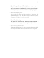
PRAYER TIME BY USING ALTERA DE2 BOARD
NORAZMAN BIN HUSSIN
Submitted to the Faculty of Electrical Engineering
in partial fulfilment of the requirement for the degree of
Bachelor Degree of Engineering (Computer)
Faculty of Electrical Engineering
Universiti Teknologi Malaysia
APRIL 2010
v
Specially dedicated to
my beloved mother, father, brothers and sister who have
encouraged, guided and inspired me throughout my journey of education.
vi
ACKNOWLEDGEMENT
I would like to take this opportunity to express my deepest gratitude to my
supervisor, Dr. Muhammad Nadzir Bin Marsono who has persistently assisted me in
completing this project. He has given me support and insight in doing this project
and has patiently listed and guided.
I would also like to express my special thanks to Dr. Shaikh Nasir Bin Shaikh
Husin who was supervised me for Final Year Project 1 to overcome problems during
the course of the project. A Special appreciation I gave to my beloved family
especially my parents for their concerns and prayer in accomplishing this project.
I am grateful that I have received help and support from friends. My special
thanks to Mr. Jeffri Bin Ismail and Mr. Khomarudden Bin Mohd Khair Juhari who
are technicians for given me using any equipment inside ECAD laboratory for this
project. It is my greatest thanks and joy that I have met with these people. Thank
you.
vii
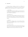
ABSTRACT
It is an obligation on Muslims to perform the obligatory prayers whenever
they are at specific times of the day. The prerequisite of prayers knows the time for
that prayer times. Traditionally this has been based on position of the sun and stars at
night. However the science and mathematics of astronomy have advanced, in part
due to above requirements. Precise algorithms based on geographical position
(latitude and longitude) are established to determined the exact prayer times. This
project utilities these algorithms and implement it on a Field Programmable Gates
Array (FPGA) based system. The FPGA is using C programming code to determine
the prayer time. This is an alternative to keying in geographical position to determine
the prayers times.
viii
ABSTRAK
Tanggungjawab seorang Muslim adalah untuk mengerjakan Ibadah Solat di
mana sahaja mereka berada dan pada masa yang telah ditetapkan. Untuk melakukan
Ibadah Solat, seorang itu perlu mengetahui waktu sembahyang tersebut. Sebelum ini,
penetapan waktu sembahyang telah dibuat berdasarkan kedudukan matahari dan
bintang pada malam hari. Bagaimanapun, peningkatan dalam ilmu sains dan
matematik telah membantu dalam menentukan kedua-dua prasyarat tersebut.
Algoritma yang tepat berdasarkan kedudukan geografi (latitud dan longitud) telah
dihasilkan untuk menentukan waktu solat. Projek ini dilaksanakan menggunakan
algoritma tersebut dan diimplimenkan menggunakan sistem Lapangan Aturcara Get
Logik (FPGA). Lapangan Aturcara ini diintegrasikan menggunakan pengaturcaraan
C untuk menentukan waktu solat. Ini merupakan satu cara alternatif untuk
menggunakan kedudukan geografi dalam menentukan waktu solat.
ix
TABLE OF CONTENTS
CHAPTER
1
2
TITLE
PAGE
DECLARATION
iv
DEDICATION
v
ACKNOWLEDGEMENT
vi
ABSTRACT
vii
ABSTRAK
viii
TABLE OF CONTENTS
ix
LIST OF TABLES
xi
LIST OF FIGURES
xii
LIST OF ABBREVIATIONS
xiii
INTRODUCTION
1.1 Times of Solat
1
1.2 Problems Statement
2
1.3 Objectives
2
1.4 Work Scope
3
BASIC CONCEPT AND THEORY
2.1
Introduction
4
2.2
Definition of prayer times
5
2.3
Calculation of Solat Times
7
2.4
Related work
12
x
3
4
DESIGN AND DEVELOPMENT
3.1 Introduction
14
3.2 Main Process
14
3.3 Hardware Development process
16
3.4 Software Development process
20
SOFTWARE DESIGN AND DEVELOPMENT
4.1 Introduction
22
4.2 Embedded C programming
23
4.3 Assembly Language
23
4.4 Software Development environment
24
4.4.1 Altera Quartus II environment
24
4.4.2 Altera Nios II environment
27
4.5 Detail Design
5
6
REFERENCES
APPENDIXES
30
RESULT AND DISCUSSION
5.1 Introduction
32
5.2 The Device
32
5.3 Working The Device
33
5.4 Seeing The Prayer Times
34
5.5 Fits the Date
35
5.6 Fits the Time
37
5.7 Fits the Location
38
5.8 Discussion
40
CONCLUSION AND FURTHER WORK
6.1 Conclusion
41
6.2 Further Work
42
xi
LIST OF TABLES
TABLE
TITLE
PAGE
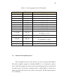
2.1
Twilight angle of different Organization
11
3.1
Pin assignments for the LCD module
20
4.1
Pinout of the target connector
28
xii
LIST OF FIGURES
FIGURES
TITLE
PAGE
2.1
Position of prayer times
7
2.2
Graph of Declination angle (D) versus Month
8
2.3
Graph of Equation of Time (T) versus Month
9
2.4
Malaysia latitude and longitude
13
3.1
Flow chart of Main Process
15
3.2
The DE2 board
16
3.3
Schematic diagram of the 7-segment displays
18
3.4
Position and index of each segment in a 7-segment
18
displays
3.5
Schematic diagram of the LCD module
19
4.1
Typical CAD flow chart
25
4.2
Nios Hardware and Software interface
27
4.3
JTAG connector
29
4.4
Prayer Time flow chart
31
5.1
I/O configuration on DE2 board
33
5.2
Begin Operation
34
5.3
Prayer Time displayed
35
5.4
Setting year
36
5.5
Setting month
36
5.6
Setting day
36
5.7
Setting hour
37
5.8
Setting minute
37
5.9
Location displayed
39
xiii
LIST OF ABBREVIATIONS
AC
-
Alternating Current
DC
-
Direct Current
DIP
-
Dual Inline Package
FSR
-
File Select Register
GND
-
Ground
GPR
-
General Purpose Register
LCD
-
Liquid Crystal Display
WDT
-
Watch Dog Timer
EEPROM
-
Electronically Erasable Read-only
Memory
PWM
-
Pulse Width Modulation
RISC
-
Reduce Instruction Set Computer
CPU
-
Central Processing Unit
SSP
-
Synchronous Serial Port
ICSP
-
In-Circuit Serial Port
IO
-
Input Output
PC
-
Personal Computer
DIY
-
Do It Yourself
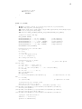
CHAPTER 1
INTRODUCTION
1.1
Times of Solat
Solat times are set in such a way that there is continuous communication with
the creator. There are times in which Solat cannot be offered. Prayer is not allowed at
sunrise and sunset to avoid confusion with worshippers of the sun. The obligatory
prayers need to be performed during their times. Currently, specific astronomical
theories based Quran and Hadith are being used on deciding each time prayer. It is
said in Quran (which means):
“When ye have performed the act of worship, remember Allah, standing, sitting and
reclining. And when ye are in safety, observe proper worship. Worship at fixed times
hath been enjoined on the believers.”
(Surah al-Nisaa’: 103)
2
1.2
Problem Statements
It is hard to know the prayer of each prayer times. In the old days, people use
stick and sees is shadow to know the prayer times. Nowadays, astronomical
researches and findings are used in computing the prayer time.
There are several applications on the Internet that calculate prayer times.
They have to insert information on current location and prayer information will be
given. As the technologies grow, various mobile companies’ gives prayer time
services. The problem is that the applications itself are not portable, self generated
but rely on the service itself. Services from websites need the user to have internet
connections making it not practical for daily use.
People exchange the daily change from a place to another one and they needs
to know the time of the prayer in the present place that they goes. By the way, people
somehow need to ask which lives in that place. The problem is when somebody
moves to a place that it has rarely Muslim. It can be that it does them that they
confused and that they vacillated to request in there.
1.3
Objectives
This project is prepared to reach some objectives that are to identify the given
entrance and later to exhibit the exit depending of entrance. It will recognize four
push buttons like Mode, Select, Back and Next. Secondly, to discover an advisable
algorithm that use to write the C or C++ code programming in Quartus II and Nios II
to obtain the real hardware made by using DE2 board. This method will need
3
software to turn it. Finally, to learn more on Quartus II and Nios II that program
more popular is used to solve a problem in directing the field for FPGA.
1.4
Work Scope
The scopes and guidelines in this project are listed to ensure the project is
conducted within its intended boundary. This is ensuring the project is leading in the
right direction to achieve the objectives of this project.
The first scope of this project is to implement a device that can find time
prayer based on date, time and location.
Secondly, using an end product device such as DE2 board, and programmed
it to make it works like as planning.
The development of the application is made using C programming code
where it builds at Nios2 to program into FPGA inside the DE2 board. By the way,
Quartus is used to declare the hardware at DE2 board.
CHAPTER 2
BASIC CONCEPT AND THEORY
2.1
Introduction
The five Islamic prayers name Subuh, Zuhur, Asar, Maghrib and Isyak. The
synchronization of these five prayers varies from a site to another one and day per
day. It is obligatory so that the Muslims make these prayers at the correct time.
The prayer times for any location given in the Earth can mathematically be
determined if the latitude and the longitude of the location are known. Nevertheless,
the theoretical determination of the prayer times is a very long process. Of this
tediousness it can much be alleviated using computer programs.
5
2.2
Definition of prayer times
There are the quotations of Quran that define the importance of making
prayer in the specific moment and to be obligatory to follow the time of the prayer
(which means):
“When ye have performed the act of worship, remember Allah, standing, sitting and
reclining. And when ye are in safety, observe proper worship. Worship at fixed times
hath been enjoined on the believers.”
(Surah al-Nisaa’: 103)
“Therefore be patient with what they say, and celebrate (constantly) the praises of
thy Lord, before the rising of the sun, and before its setting; yea, celebrate them for
part of the hours of the night, and at the sides of the day: that thou mayest have
(spiritual).”
(Surah Toha: 130)
Hadith related that verify the prayer time which means: Ibn ‘Abbas said, The
Messenger of Allah, peace and blessings of Allah be on him, said:
“Gabriel acted as imam for me twice in the (Sacred) House; so he said the Zuhur
prayer with me when the sun had declined from the meridian and (the shadow) was
the measure of a thong, and he said the Asar prayer with me when the shadow of
everything was the like of it, and he said the Maghrib prayer with me when one who
fasts breaks at fast, and he said the Isyak prayer with me when redness in the horizon
had disappeared, and he said the Subuh prayer with me when food and drink are
prohibited to one who fasts. When it was the next day, he said with me the Zuhur
prayer when the shadow (of a thing) was the like of it, and he said with me the Asar
prayer when the shadow (of a thing) was its double, and he said with me the Maghrib
prayer when one who fasts breaks the fast, and he said with me the Isyak prayer
when one-third of the night had passed, and he said with me the Subuh prayer when
6
the dawn was bright. Then he turned to me and said, O Muhammad! This is the time
of the prophets before thee, and the time is between these two times.”
(Ad. Tr-Msh. 4:1)
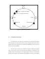
Each prayer must be made in its specified time. The definition of hourly of
the prayer based on al-Quran and Hadith is follows:
•
SUBUH starts with the dawn or morning twilight. Subuh ends just before
sunrise.
•
ZUHUR begins after midday when the trailing limb of the sun has passed
the meridian. For convenience, many published prayer timetables add
five minutes to mid-day (zawal) to obtain the start of Zuhur. Zuhur ends
at the start of Asar time.
•
The timing of ASAR depends on the length of the shadow cast by an
object. According to the Shafi School of jurisprudence, Asar begins when
the length of the shadow of an object exceeds the length of the object.
According to the Hanafi School of jurisprudence, Asar begins when the
length of the shadow exceeds TWICE the length of the object. In both
cases, the minimum length of shadow (which occurs when the sun passed
the meridian) is subtracted from the length of the shadow before
comparing it with the length of the object.
•
MAGHRIB begins at sunset and ends at the start of Isyak.
•
ISYAK starts after dusk when the evening twilight disappears.
7
Mid-day
Shadow = length+ noon shadow
Shadow = 2 x length+ noon shadow
Sunset
Sunrise
Twilight ends
Twilight begins
Midnight
Figure 2.1 : Position of prayer times
2.3
Calculation of Solat Times
To calculate the prayer times for a certain place we need to know the latitude
(B) and longitude (L) of the location and its reference longitude (R). B and L may be
obtained from an atlas and R may be calculated by multiplying 15 by the reference
between local time and GMT.
One also need to know two astronomical measures called the declination
angle of the sun (D) and the real time-mean time difference, also known as the
equation of time (T). Declination is the angular distance between a celestial object
and the celestial equator. The Declination and the Right Ascension are used together
8
to give the position of a star with reference to the celestial equator and the vernal
equinox respectively.
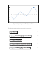
The equation of the time is a correction to be added to apparent solar time, as
read on a sundial, to obtain means solar time, as commonly used. This difference is a
consequence of the elasticity and tilt of the Earth’s orbit, causing the irregular
apparent movement of the Sun across the sky. D and T vary according to the time of
year and can be obtained accurately from The Star Almanec or approximate.
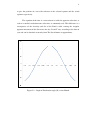
Figure 2.2 : Graph of Declination angle (D) versus Month
9
Figure 2.3 : Graph of Equation of Time (T) versus Month
The following equation may be used to calculate the prayer times:
.....1
.....2
.....3
.....4
.....5
10
Where:
B = latitude of place
D = longitude of place
R = reference longitude (i.e. TIME BAND x 15)
H = height above sea level (in metres)
D = declination angle of sun from celestial equator (negative in southern
hemisphere)
T = equation of time
G = twilight angle
• Subuh = Z - V
• Sunrise = Z – U
• Zuhur = Z
• Asar1 (Shafi) = Z + W
• Asar2 (Hanafi) = Z + X
• Maghrib/Sunset = Z + U
• Isyak = Z + V
The algorithm to calculate T and D are not shown here. Zuhur time is
calculated using Equation 1. The time for sunrise and sunset/Maghrib may be
calculated by subtracting or adding ‘U’ (obtained from Equation 2) to the Zuhur time
respectively.
Subuh and Isyak times may be calculated by subtraction or adding ‘V’
(obtained from Equation 3) to the Zuhur time respectively. The term G (twilight
angle) in Equation 3 is usually set to 18 degrees. For a location with extreme latitude,
days in summer may be so long that twilight persists between sunset and the next
sunrise. Under these circumstances, ‘V’ is undefined and Subuh and Isyak have to be
determined using agreed principles of Fiqh.
11
The start of Asar time (Shafi) may be obtained by adding ‘W’ (obtained from
Equation 4) to Zuhur; Asar time (Hanafi) is calculated by adding ‘X’ (obtained from
Equation 5) to Zuhur.
Zuhur, Asar (Shafi and Hanafi) and Maghrib times may be calculated
unambiguously. But Subuh and Isyak times depend on twilight and required the
adoption of a suitable twilight angle. Generally, a twilight angle of 18 degrees may
represent a safe upper limit although opinions and practices vary. In locations at
higher latitude, twilight may persist throughout the night during some months of the
year.
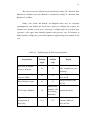
Table 2.1 : Twilight angle of different Organization
Organization
Subuh
Isyak
Twilight
Twilight
angle
angle
Region
Pakistan, Bangladesh,
University of Islamic
18
18
India, Afghanistan, parts
Sciences, Karachi
of Europe
Islamic Society of North
Parts of USA & Canada,
15
15
America (ISNA)
parts of UK
Europe, Far East, parts
World Islamic League
18
17
of USA
90 mins after
Maghrib, 120
Um Ul-Qura, Makkah
19
Arabian Peninsula
mins during
Ramadhan
Egyptian General
Organisation of
Surveying
Africa, Syria, Iraq,
19.5
17.5
Lebanon, Malaysia,
parts of USA
12
2.4
Related work
Malaysia, in the south east part of Asia, has a geographic coordinate that reads
2° 30' North latitude and 112° 30' East longitude. Kuala Lumpur which is the capital
of Malaysia is located in between 3° 10' North latitude and 101° 42' East longitude.
As a result of its latitude and longitude, Malaysia stays ahead by eight hours from the
Greenwich Mean Time. Malaysia has several types of landscapes for its certain
latitude and longitude measurements.
Malaysia has tropical weather, influenced by monsoonal climate because of its
latitude and longitude. Tropical climate here gives hot summer that is accompanied
with high humidity level. But the weather in general in Malaysia is without
extremities. Monsoon comes twice a year. During the summer season and the other
during winter. Summer monsoon brings lots of downpour in Malaysia. Winter
monsoon does not cause that much rain and is generally dry.
13
Figure 2.4 : Malaysia latitude and longitude
CHAPTER 3
DESIGN AND DEVELOPMENT
3.1
Introduction
This chapter discusses the main process, hardware development and software
development. In main process, it contains how to choose device can be used in this
project, implement the hardware, testing and verification.
The second process is hardware development that will be discussed about
the specification of device that was choosing in main process. Finally, software
development process will discuss the conceptual and planning phase, development
process, troubleshooting, testing and verification.
3.2
Main Process
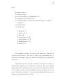
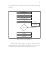
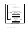
Figure 3.1 below shows the main process of the Prayer Time Device.
Literature review were done to study all devices related followed by selecting device
15
needed. The device that was selected based on the software that must used to develop
this project.
Literature Review
Select Device
Software Programming
Testing
Troubleshoot and
repair bugs
Error
Verification
End product
Figure 3.1 : Flow chart of Main Process
DE2 board was used in designing and implement the hardware before
programming the codes in software. Testing and verifications need to be carried out
to ensure the results are reliable and achieves the objectives of the project.
16
3.3
Hardware Development process
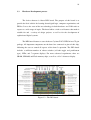
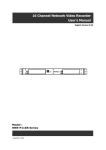
The device choosen is Altera DE2 board. The purpose of this board is to
provide the ideal vehicle for learning about digital logic, computer organization, and
FPGAs. It uses the state-of-the-art technology in both hardware and CAD tools to
expose to a wide range of topics. The board offers a rich set of features that make it
suitable for and a variety of design projects, as well as for the development of
sophisticated digital systems.
The DE2 board features a state-of-the-art Cyclone II 2C35 FPGA in a 672-pin
package. All important components on the board are connected to pins of this chip,
following the user to control all aspects of the board’s operation. The DE2 board
includes a sufficient number of robust switches (of both toggle and push-button
type), LEDs, and 7-segment displays. For more advanced experiments, there are
SRAM, SDRAM, and Flash memory chips, as well as a 16 x 2 character display.
Figure 3.2 : The DE2 board
17
Software provided with the DE2 board features the Quartus II Web Edition
CAD system, and the Nios II Embedded Processor. Also included are several aids to
help userd with features of the board, such as tutorials and example applications.
Traditionally, manufacturers of educational FPGA boards have provided a
variety of hardware features and software CAD tools needed to implement designs
on these boards, but very little material has been offered that could be used directly
for teaching purposes.
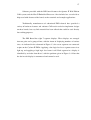
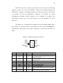
The DE2 Board has eight 7-segment displays. These displays are arranged
into two pairs and a group of four, with the intent of displaying numbers of various
sizes. As indicated in the schematic in Figure 3.3, the seven segments are connected
to pins on the Cyclone II FPGA. Applying a low logic level to a segment causes it to
light up, and applying a high logic level turns it off. Each segment in a display is
identified by an index from 0 to 6, with the positions given in Figure 3.4. Note that
the dot in each display is unconnected and cannot be used.
18
Figure 3.3 : Schematic diagram of the 7-segment displays.
Figure 3.4 : Position and index of each segment in a 7-segment display.
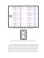
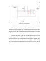
The LCD module has built-in fonts and can be used to display text by sending
appropriate commands to the display controller, which is called HD44780. Detailed
information for using the display is available in its datasheet, which can be found on
the manufacturer's web site, and from the Datasheet folder on the DE2 System CDROM. A schematic diagram of the LCD module showing connections to the Cyclone
II FPGA is given in Figure 3.5. The associated pin assignments appear in Table 3.1.
19
Figure 3.5 : Schematic diagram of the LCD module.
20
Table 3.1 : Pin assignments for the LCD module.
Signal Name
FPGA Pin No.
Description
LCD_DATA[0]
PIN_J1
LCD Data[0]
LCD_DATA[1]
PIN_J2
LCD Data[1]
LCD_DATA[2]
PIN_H1
LCD Data[2]
LCD_DATA[3]
PIN_H2
LCD Data[3]
LCD_DATA[4]
PIN_J4
LCD Data[4]
LCD_DATA[5]
PIN_J3
LCD Data[5]
LCD_DATA[6]
PIN_H4
LCD Data[6]
LCD_DATA[7]
PIN_H3
LCD Data[7]
LCD_RW
PIN_K4
LCD Read/Write Select,
0 = Write, 1 = read
LCD_EN
PIN_K3
LCD_RS
PIN_K1
LCD Enable
LCD Command/Data Select,
0 = Command, 1 = Data
3.4
LCD_ON
PIN_L4
LCD Power ON/OFF
LCD_BLON
PIN_K2
LCD Back Light ON/OFF
Software Development process
The development process of the software was done using The Spiral Model.
The model originally proposed by Boehm [BOE88] is an evolutionary software
process model that couples the iterative nature of prototyping with the controlled and
systematic aspects of the linear sequential model. A Spiral Model is divided into a
number of framework activities also called as task regions. The Development phases
are as following:
21
• Phase 1 : Conceptualization and Planning Phase
This phase is where the planning of the project is done. The specifications
that are being taken are the main objective, the project scope, time frame of
the development process and sources needed in accomplishing the projects.
• Phase 2 : Development process
After deciding the concepts and the prerequisites of the projects, this
implementation phase is done. The software design was carried out by coding
the program and this phase is very time consuming.
• Phase 3 : Troubleshooting
The software and the hardware are implemented together. Debugging is
carried out to overcome any logical flaws in algorithm implementation.
• Phase 4 : Testing and Verification
Testing and verification have to be made to ensure the softwares are reliable.
Data comparisons with the standard output from other sources are applied.
CHAPTER 4
SOFTWARE DESIGN AND DEVELOPMENT
4.1
Introduction
This chapter discusses the embedded C coding, the assembly language,
software development environment and detail design. A part of the declaration of the
hardware is the same reason of the assembly language of the use.
For the software development environment, Quartus and Nios was chooses.
It is because for the Altera hardware need to use Altera software tool to make it will
program successfully. For the software development environment, Quartus and Nios
were chooses. It is because so that the necessity of the Altera hardware it uses the
tool of the Altera software to do will program successfully it. In detail design, it will
demonstrate that the design has become and to elaborate the function for that
product.
23
4.2
Embedded C programming
The software part presented is written in C high-level language. C that it
programs provides really more convenience for the new users reducing to the
minimum the necessity to understand the architecture of the microcontroller itself of
the detail and to stress more in the programming algorithms. This means that the C
programming can help the user to focus of how making a routine functional to
smoothly work the code rather that spends the time that thinks about where to put the
data and the code.
With C high-level programming, the users they will only need to know how
to write the code rather than to knowing how the microcontroller executes codes to
the wished result. Inevitable which it continues being a necessity to understand the
architectonic structures of registries and the file of data of the microcontroller, the
users can make use the structure of C programming language save more hour
studying the codes for LCD, seven segments, microcontroller and the ways to
integrate them together.
4.3
Assembly language
Apart from the complexity of assemble code, assembly language is important
in the microcontroller where it allows users to supervise each aspect of the program.
Another advantage of the assembly language is the resources available in the Internet
where one can just download most of the demo and example code in this language
format. The disadvantage of the C code language is that the compiled size is
generally more length than assembly language. In this project, verilog was used like
assembly language.
24
4.4
Software Development environment
For this project, there is development with two aspects that are development
of hardware and software. For the hardware development, Quartus of Altera’s
software is used with verilog language to declare the hardware. By the way, software
development cannot the same software because it does not have equal like the
hardware. Nios also as Altera’s software used for develops the software development
that is using programming C code programming language.
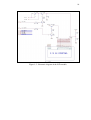
4.4.1 Altera Quartus II environment
For Quartus environment, Computer Aided Design (CAD) software makes it
easy to implement a desired logic circuit by using a programmable logic device, such
as a field-programmable gate array (FPGA) chip. A typical FPGA CAD flow is
illustrated in Figure 4.1.
25
Design Entry
Synthesis
Functional Simulation
No
Design correct?
Yes
Fitting
Timing Analysis and Simulation
No
Timing requirement met?
Yes
Programming and Configuration
Figure 4.1 : Typical CAD flow chart
It involves the following basic steps:
• Design Entry
The desired circuit is specified either by using a hardware description
language, such as Verilog or VHDL, or by means of a schematic diagram.
26
• Synthesis
The CAD Synthesis tool synthesizes the circuit into a netlist that gives the
logic elements (LEs) needed to realize the circuit and the connections
between the LEs.
• Functional Simulation
The synthesized circuit is tested to verify its functional correctness; the
simulation does not take into account any timing issues.
• Fitting
The CAD Fitter tool determines the placement of the LEs defined in the
netlist into the LEs in an actual FPGA chip; it also chooses routing wires
in the chip to make the required connections between specific LEs.
• Timing Analysis
Propagation delays along the various paths in the fitted circuit are analyzed
to provide an indication of the expected performance of the circuit.
• Timing Simulation
The fitted circuit is tested to verify both its functional correctness and
timing.
• Programming and Configuration
The designed circuit is implemented in a physical FPGA chip by
programming the configuration switches that configure the LEs and
establish the required wiring connections.
27
4.4.2 Altera Nios II environment
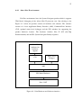
For Nios environment, have the System Navigator product which is supports
JTAG-based debugging of the Altera Nios II processor core. By referring to the
Figure 4.2 below, the product consists of hardware and software. The software
consists of a host Application Binary Interface (ABI), Command-Line Interface
(CLI), optional source-level debugger and the FS2 windows for supporting the
product hardware features. The hardware includes Nios II OCI (On-Chip
Instrumentation) and the FS2 System Navigator Family of probes.
FS2 GUI
windows for
hardware
support
Souce-level
debugger
CLI
ABI
FS2 Probe Hardware
Nios 2 OCI
Figure 4.2 : Nios Hardware and Software interface
28
The CLI can be used as both a user interface and as a means of automating
sequences of tasks. It is based on TCL/TK, a widely used command language and
GUI builder. A number of command primitives and Tcl procedures have been added
to customize Tcl for this application. Commands are included for system
configuration, emulation control, memory access including an assembler and
disassembler, register access, trace and trigger access, file download, and status
indication.
The probe uses a 10-position flat ribbon cable with standard 0.100” square
post headers. A connector with an orientation key such as 3M 2510-6002UB is
recommended. The pinout of the target connector is described in the Table 4.1
below.
Table 4.1 : Pinout of the target connector
TCK
TDD
TMS
Debugack
TDI
1 2
3 4
5 6
7 8
9 10
Pin
2, 10
Signal
GND
I/O
--
Active
--
4
VCC
|
--
6
VIO
|
--
1
3
5
9
TCK
TDO
TMS
TDI
O
|
O
O
H
H
H
H
7
Debugack
|
H
8
Debugreq
O
H
GND
VCC
VIO
Debugreq
GND
Comments
Signal reference
Power source for debugger (Not used by
System Navigator)
Used by debugger to determine target
power-on state.
JTAG test clock
JTAG test data output
JTAG test mode select
JTAG test data input
Optional signal indicating CPU is in debug
mode
Debug interrupt request (optional)
29
Figure 4.3 : JTAG connector
If the Nios II processor is part of a chain of JTAG devices, whether all on the
same physical chip or on separate chips, the devices should be connected in a daisychain with TCK and TMS common to all devices and TDO from one device leading
to TDI of the next.
For targets that include the off-chip Trace Port, FS2 provides the System
Navigator Original Edition (OE/T) probe with a high-speed ribbonized coax
connection to the target. Trace data is compressed then multiplexed onto this cable.
The probe demultiplexes the trace data and stores it in high-speed SRAM. Off-chip
trace is typically much deeper than on-chip trace but requires use of several chip I/O
pads.
30
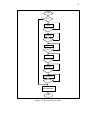
4.5
Detail Design
Before the Prayer Time constructed, some of the requirements need to know
first. This is because to do that successfully it works without any error. The
requirements need to know are year, month, day, time, minute and location. The
Prayer Time developed is based on flow chart in Figure 4.4 to works correctly
whereas we wanted that it did.
Based on the flow chart below, year, month, day, hour, minute and location
need to insert manually. Once you push the Mode button, it will loop until the
location inserted. After all requirements inserted, the time and the prayer time will
exhibit in seven segments in DE2 board. One of 16 LEDs will blink as second
indicator. If the time and the prayer time are equal, 16 LEDs blinking in 60 seconds
together. After that, the next prayer time will exhibit like Subuh, Zohor, Asar,
Maghrib and Isyak respectively. Continuously direct operation until it is the energy
unplugs.
31
START
no
Mode
yes
YEAR
Select
no
yes
MONTH
no
Select
yes
DAY
Select
no
yes
HOUR
Select
no
yes
MINUTE
Select
no
yes
LOCATION
Select
no
yes
TIME &
PRAYER TIME
END
Figure 4.4 : Prayer Time flow chart
CHAPTER 5
RESULT AND DISCUSSION
5.1
Introduction
This chapter discusses on the device, working the device, seeing the prayer
times, fits the date, location and time. For the device it mainly discussed the
component in DE2 board are used. In the operation of the device it discusses how to
know that the device begins.
In seeing the prayer time, it will discuss how the time of the prayer can be
recognized. According to adjustment the date, time and location it is demonstrations
like user manual.
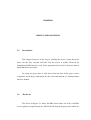
5.2
The Device
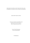
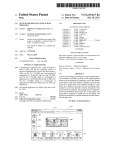
The device in Figure 5.1 shows the DE2 board where use LCD, red LEDs,
seven segments and push button are. The LCD will display the prayer time which are
33
Subuh, Zohor, Asar, Maghrib and Isyak. The seven segments will display number for
year, month, day, hour, minute, time and prayer time. Furthermore, all sixteen red
LEDs are used to indicate the time for pray. Besides that, all four push buttons are
used as input which are Mode, Select, Back and Next. The figure below shows the
specification was discussed above.
Figure 5.1 : I/O configuration on DE2 board
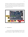
5.3
Working The Device
The device has been develop need to know either it will operation successful
or not. For this Prayer Time, it will display “PRAYER TIME” at the first row and the
second row will display “By : AZMAN” which is mean the device is begin the
34
operation. After that, it will display seven segments as time and prayer time and also
one of sixteen LEDs where it is at left hand side from user.
Figure 5.2 : Begin operation
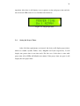
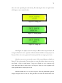
5.4
Seeing the Prayer Times
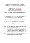
After all of the requirements are inserted, this device will display prayer times
which are Subuh, Syuruk, Zohor, Asar, Maghrib and Isyak respectively. It will
display one prayer time in one time only. For this case, if the time is same with
prayer time all red LEDs will blink in one minute. If the prayer time was past, it will
display the next prayer time.
35
Figure 5.3 : Prayer Time displayed
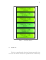
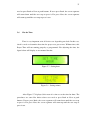
5.5
Fits the Date
This device is depending on date where it will calculate automatically if date
was inserted. The calculation will match with equation of time and declination angle
36
where it is also depending on earth moving. For adjusting the date, the figure below
will display as user manual for that.
Figure 5.4 : Setting year
Figure 5.5 : Setting month
Figure 5.6 : Setting day
After Figure 5.4 displayed, user need to press Back or Next at push buttons. If
users press Back, the seven segments will count down until the user stop to press it.
For press Next, the seven segments will count up until the user stop to press it too.
After the year was set, user needs to press Select at push button to display at
Figure 5.5 for set the month. The procedures are same like before where user need to
press Back or Next at push buttons. If users press Back, the seven segments will
count down until the user stop to press it. For press Next, the seven segments will
count up until the user stop to press it too.
After the month was set, user needs to press Select at push button again to
display at Figure 5.6 for set the day. The procedures are same like before where user
37
need to press Back or Next at push buttons. If users press Back, the seven segments
will count down until the user stop to press it. For press Next, the seven segments
will count up until the user stop to press it too.
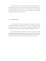
5.6
Fits the Time
Time is very important to in all devices are depending on clock. In this case,
clock is needs to determine that time for prayer was past or not. Without time, this
Prayer Time will not running properly as programmed. For adjusting the time, the
figure below will display as user manual for that.
Figure 5.7 : Setting hour
Figure 5.8 : Setting minute
After Figure 5.7 displayed, this mean it is time to set the time for hour. The
procedures are same like before where user need to press Back or Next at push
buttons. If users press Back, the seven segments will count down until the user stop
to press it. For press Next, the seven segments will count up until the user stop to
press it too.
38
After the hour was set, user needs to press Select at push button again to
display at Figure 5.8 for set the day. The procedures are same like before where user
need to press Back or Next at push buttons. If users press Back, the seven segments
will count down until the user stop to press it. For press Next, the seven segments
will count up until the user stop to press it too.
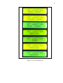
5.7
Fits the Location
In this prayer time, locations are important too like time. This is because,
without location, prayer time is nothing use because it is also depending on location
too. For this project there are seven locations are programmed to DE2 board which
are Batu Pahat, Johore Bahru, Kota Tinggi, Mersing, Muar, Pontian and Segamat.
For the default location is Batu Pahat. If users press Back, the location
displayed will reverse alphabet respectively until the user stop to press it. For press
Next, the location displayed will forward alphabet respectively until the user stop to
press it too. The Figure was discussed above will displayed below as reference.
39
Figure 5.9 : Location displayed
40
5.8
Discussion
In Malaysia, most of the Malaysians are Muslim. That why some of the
organization exists to guide and protecting human right from some human want to
diversion and will blind the human right or illegal. A familiar of the organization in
Malaysia is Jabatan Kemajuan Islam Malaysia (JAKIM). Any things who want to
build dependent on religion, Islam mostly need to use their procedure.
Return back to the Prayer Time device, it is need to use JAKIM guide if it
want to market widely. It is because, to valid that time for prayer especially during
Ramadhan also known as fasting month for sure to eat after fasting a whole day. For
this situation, we used JAKIM as our reference prayer time. Unfortunately this end
product is not accurately like JAKIM’s prayer time. It is rounded about more or less
2 minutes for Subuh, Maghrib and Isyak although used twilight angle are 20° and
18° for Subuh and Isyak respectively.
CHAPTER 6
CONCLUSION AND FURTHER WORK
6.1
Conclusion
This project offers simple and efficient way to find the Prayer Time based on
knowing the location of that area. The portable and automated design make it as a
device that be used in any places, bulky and some needs Internet connection to get
this service.
The user friendly interface and simple instruction will help people in getting
fast result in any places at any time without having using other resources. It is also
using the same calculation method with Jabatan Kemajuan Islam Malaysia (JAKIM)
where as 20° and 18° twilight angle for Subuh and Isyak respectively.
Unfortunately, this Prayer Time Device uses only 9V DC Wall-mount power
supply makes it hard to use at any places without socket plug. In another weakness of
this device is date, time andcurrent location have to be inserted manually by user
every time to operate the system. The recommendation part will discuss on how to
improve the weakness and ways to make the device better.
42
6.2
Further Work
The project develop is functioning well with no error. However, the
development of Prayer Time device can be improved to a more advanced and better
application in further. For further improvement, several suggestions are proposed:
• Automatic Input
By using the Global Positioning System (GPS), date, time and location can be
set automatically by connecting GPS with the DB-9 serial connector and
interface with RS-232 to the DE2 board.
• Better Hardware used
The device can be use smaller than DE2 board or build on their own but it is
still using this concept. In another way, this project will build in with battery
for easy used. It will smaller (pocket size) and easier to bring the device
anywhere.
• Add function
This device can be multipurpose device, not only determining the Prayer
Time but also can show Hijrah Calendar. It can also be a table watch with
alarm function and so forth.
• Use memory to store data
This device will need to insert date, time and location for the first time used
where all the first data will stored in temporary Read-Only Memory (ROM)
although the device doesn’t have power to make it easy to use again.
REFERENCES
1.
Rais Ayop, Analisa waktu solat global. Bachelor Degree in Science (Land
Administration & Development). Universiti Teknologi Malaysia; 1998.
2.
Nurunnuha Md Hatta, Panduan waktu solat interaktif. Bachelor Degree in
Computer Science. Universiti Teknologi Malaysia; 2001.
3.
Nuradzi Ahmad, Pembangunan perisian perhitungan waktu solat mudah
pengguna.
Bachelor
Degree
in
Science
(Land
Administration
&
Development). Universiti Teknologi Malaysia; 1997.
4.
Mohd Azharis Md Suhrie, Rekabentuk sistem jam waktu solatl. Bachelor
Degree in Engineering (Geomatic). Universiti Teknologi Malaysia; 2002.
5.
Zamri Seman, Waktu solat interaktif. Bachelor Degree in Engineering
(Geomatic). Universiti Teknologi Malaysia; 2004.
6.
Mohd Izwan Bin Ismail. Chess Clock in Hardware Description Language.
Bachelor Degree in Electronic Engineering. Universiti Teknologi Malaysia;
2007
7.
Zulfakar Aspar. Digital IC Design using Altera FPGA. 1st Edition. Malaysia;
Pearson Prentice Hall. 2007.
8.
Mohamed Khalil Hani. Digital Systems VHDL & Verilog Design. 2nd Edition.
Malaysia; Pearson Prentice Hall. July 2009.
9.
Nasly Mohamed Ali and Haniisah Abu Azam. Structured Programming
Using C++ in simple steps with Engineering Applications. 1st Edition.
Malaysia; Desktop Publisher. 2010.
10.
Norazah Yusof, Programming Technique II. 2nd Edition. Malysia; Desktop
Publisher. 2009
11.
Mariani Abu Bakar, Pengaturcaraan C. 1st Edition. Malaysia; Prentice Hall.
2002.
12.
Stephen Brown, Fundamental of Digital Logic with VHDL Design. 2nd
Edition. Toronto; Mc Graw Hill.
APPENDIX A
Hardware schematic diagram
45
APPENDIX B
Programming In C Language
47
a. prayer.c (Top-level file)
#include
#include
#include
#include
#include
#include
#include
<stdio.h>
<math.h>
<unistd.h>
"altera_avalon_pio_regs.h"
"system.h"
"DE2.hch"
"header.h"
void main(void)
{
int i,time,sub,syu,zho,asr,mag,isy;
int h3,h2,h1,h0;
int day,min,hour,lat,lon;
int button=IORD_ALTERA_AVALON_PIO_DATA(BUTTON_PIO_BASE);
DE2_LCD_LINE line;
line = hex2ascii() @ sp @ sp @ sp @ P @ R @ A @ Y @ E @ R @ sp @
T @ I @ M @ E @ sp @ sp @ sp @ sp @ sp @ B @ y @ sp @ : @ sp @ A @ Z
@ M @ A @ N @ blank_line<-152;
DE2LCDDriver(line);
DE2_SDRAM SDRAM;
DE2ReadSDRAM(0x000003, hour, SDRAM);
DE2ReadSDRAM(0x000004, min, SDRAM);
DE2SDRAMDriver(&SDRAM);
time=(hour*100)+min;
while(1){
DE2_SDRAM SDRAM;
DE2ReadSDRAM(0x000005, sub,
DE2ReadSDRAM(0x000006, syu,
DE2ReadSDRAM(0x000007, zho,
DE2ReadSDRAM(0x000008, asr,
DE2ReadSDRAM(0x000009, mag,
DE2ReadSDRAM(0x00000A, isy,
DE2ReadSDRAM(0x00000B, lat,
DE2ReadSDRAM(0x00000C, lon,
DE2SDRAMDriver(&SDRAM);
SDRAM);
SDRAM);
SDRAM);
SDRAM);
SDRAM);
SDRAM);
SDRAM);
SDRAM);
//real-time prayer
while(i<60){
if(button=0x7){
tahun();
bulan();
hari();
jam();
minit();
location();
calc();
}
if(time>isy){
//display sub
DE2_LCD_LINE line;
48
line = hex2ascii() @ sp @ sp @ P @ R @ A @ Y @ E
@ R @ sp @ T @ I @ M @ E @ sp @ sp @ sp @ sp @ sp @ sp @ sp @ sp @ S
@ U @ B @ U @ H @ blank_line<-152;
DE2LCDDriver(line);
h3=sub/1000;
h2=(sub-(h3*1000))/100;
h1=(sub-(h3*1000)-(h2*100))/10;
h0=sub-(h3*1000)-(h2*100)-(h1*10);
h3=display(h3);
h2=display(h2);
h1=display(h1);
h0=display(h0);
DE2Set7SegDigit(3,h3);
DE2Set7SegDigit(2,h2);
DE2Set7SegDigit(1,h1);
DE2Set7SegDigit(0,h0);
}
else if(time>sub){
//display syu
DE2_LCD_LINE line;
line = hex2ascii() @ sp @ sp @ P @ R @ A @ Y @ E
@ R @ sp @ T @ I @ M @ E @ sp @ sp @ sp @ sp @ sp @ sp @ sp @ S @ Y
@ U @ R @ U @ K @ blank_line<-152;
DE2LCDDriver(line);
h3=syu/1000;
h2=(syu-(h3*1000))/100;
h1=(syu-(h3*1000)-(h2*100))/10;
h0=syu-(h3*1000)-(h2*100)-(h1*10);
h3=display(h3);
h2=display(h2);
h1=display(h1);
h0=display(h0);
DE2Set7SegDigit(3,h3);
DE2Set7SegDigit(2,h2);
DE2Set7SegDigit(1,h1);
DE2Set7SegDigit(0,h0);
}
else if(time>syu){
//display zho
DE2_LCD_LINE line;
line = hex2ascii() @ sp @ sp @ P @ R @ A @ Y @ E
@ R @ sp @ T @ I @ M @ E @ sp @ sp @ sp @ sp @ sp @ sp @ sp @ sp @ Z
@ O @ H @ O @ R @ blank_line<-152;
DE2LCDDriver(line);
h3=zho/1000;
h2=(zho-(h3*1000))/100;
h1=(zho-(h3*1000)-(h2*100))/10;
h0=zho-(h3*1000)-(h2*100)-(h1*10);
49
h3=display(h3);
h2=display(h2);
h1=display(h1);
h0=display(h0);
DE2Set7SegDigit(3,h3);
DE2Set7SegDigit(2,h2);
DE2Set7SegDigit(1,h1);
DE2Set7SegDigit(0,h0);
}
else if(time>zho){
//display asr
DE2_LCD_LINE line;
line = hex2ascii() @ sp @ sp @ P @ R @ A @ Y @ E
@ R @ sp @ T @ I @ M @ E @ sp @ sp @ sp @ sp @ sp @ sp @ sp @ sp @ A
@ S @ A @ R @ blank_line<-152;
DE2LCDDriver(line);
h3=asr/1000;
h2=(asr-(h3*1000))/100;
h1=(asr-(h3*1000)-(h2*100))/10;
h0=asr-(h3*1000)-(h2*100)-(h1*10);
h3=display(h3);
h2=display(h2);
h1=display(h1);
h0=display(h0);
DE2Set7SegDigit(3,h3);
DE2Set7SegDigit(2,h2);
DE2Set7SegDigit(1,h1);
DE2Set7SegDigit(0,h0);
}
else if(time>asr){
//display mag
DE2_LCD_LINE line;
line = hex2ascii() @ sp @ sp @ P @ R @ A @ Y @ E
@ R @ sp @ T @ I @ M @ E @ sp @ sp @ sp @ sp @ sp @ sp @ sp @ M @ A
@ G @ H @ R @ I @ B @ blank_line<-152;
DE2LCDDriver(line);
h3=mag/1000;
h2=(mag-(h3*1000))/100;
h1=(mag-(h3*1000)-(h2*100))/10;
h0=mag-(h3*1000)-(h2*100)-(h1*10);
h3=display(h3);
h2=display(h2);
h1=display(h1);
h0=display(h0);
DE2Set7SegDigit(3,h3);
DE2Set7SegDigit(2,h2);
DE2Set7SegDigit(1,h1);
DE2Set7SegDigit(0,h0);
}
50
else if(time>mag){
//display isy
DE2_LCD_LINE line;
line = hex2ascii() @ sp @ sp @ P @ R @ A @ Y @ E
@ R @ sp @ T @ I @ M @ E @ sp @ sp @ sp @ sp @ sp @ sp @ sp @ sp @ I
@ S @ Y @ A @ K @ blank_line<-152;
DE2LCDDriver(line);
h3=isy/1000;
h2=(isy-(h3*1000))/100;
h1=(isy-(h3*1000)-(h2*100))/10;
h0=isy-(h3*1000)-(h2*100)-(h1*10);
h3=display(h3);
h2=display(h2);
h1=display(h1);
h0=display(h0);
DE2Set7SegDigit(3,h3);
DE2Set7SegDigit(2,h2);
DE2Set7SegDigit(1,h1);
DE2Set7SegDigit(0,h0);
}
if((time==sub)||(time==zho)||(time==asr)||(time==mag)||(time==isy)){
IOWR_ALTERA_AVALON_PIO_DATA(LED_RED_BASE,0xFFFF);
IOWR_ALTERA_AVALON_PIO_DATA(LED_RED_BASE,0x0000);}
else{
IOWR_ALTERA_AVALON_PIO_DATA(LED_RED_BASE,0x8000);
IOWR_ALTERA_AVALON_PIO_DATA(LED_RED_BASE,0x0000);}
h3=time/1000;
h2=(time-(h3*1000))/100;
h1=(time-(h3*1000)-(h2*100))/10;
h0=time-(h3*1000)-(h2*100)-(h1*10);
h3=display(h3);
h2=display(h2);
h1=display(h1);
h0=display(h0);
DE2Set7SegDigit(7,h3);
DE2Set7SegDigit(6,h2);
DE2Set7SegDigit(5,h1);
DE2Set7SegDigit(4,h0);
i++;
}i=0;
min++;
if (min>59){
min=0;
hour++;
if (hour>23){
51
hour=0;
day++;
DE2_SDRAM SDRAM;
DE2WriteSDRAM(0x000002, day, SDRAM);
DE2SDRAMDriver(&SDRAM);
calc();
}
}
DE2_SDRAM SDRAM;
DE2WriteSDRAM(0x000004, min, SDRAM);
DE2WriteSDRAM(0x000003, hour, SDRAM);
DE2SDRAMDriver(&SDRAM);
time=(hour*100)+min;
}
}
52
b. header.h
#ifndef HEADER_H_
#define HEADER_H_
int display(int);
void tahun(void);
void bulan(void);
void hari(void);
void jam(void);
void minit(void);
void location(void);
void calc(void);
#endif /* HEADER_H_ */
53
c. header.c
#include
#include
#include
#include
"altera_avalon_pio_regs.h"
"system.h"
"DE2.hch"
<math.h>
#define d2r 0.01745329251994329576923690768489
#define r2d 57.295779513082320876798154814105
int display(int a)
{
int h;
if (a==0)
h=0x0;
if (a==1)
h=0x1;
if (a==2)
h=0x2;
if (a==3)
h=0x3;
if (a==4)
h=0x4;
if (a==5)
h=0x5;
if (a==6)
h=0x6;
if (a==7)
h=0x7;
if (a==8)
h=0x8;
if (a==9)
h=0x9;
//degrees to radians
//radians to degrees
//display seven segment
return h;
}
void tahun(void)
//display year
{
int a0,a1,a2,a3;
int tahun;
int button=IORD_ALTERA_AVALON_PIO_DATA(BUTTON_PIO_BASE);
DE2_LCD_LINE line;
line = hex2ascii() @ sp @ sp @ sp @ sp @ S @ E @ T @ sp @ D @ A
@ T @ E @ sp @ sp @ sp @ sp @ sp @ sp @ sp @ sp @ sp @ sp @ Y @ E @
A @ R @ blank_line<-152;
DE2LCDDriver(line);
while(1){
DE2_SDRAM SDRAM;
DE2ReadSDRAM(0x000000, tahun, SDRAM);
DE2SDRAMDriver(&SDRAM);
//next button
while(button=0xE){
//tahun<=memory
54
if(tahun>2060){
tahun=2010;}
a3=tahun/1000;
a2=(tahun-(a3*1000))/100;
a1=(tahun-(a3*1000)-(a2*100))/10;
a0=tahun-(a3*1000)-(a2*100)-(a1*10);
a3=display(a3);
a2=display(a2);
a1=display(a1);
a0=display(a0);
DE2Set7SegDigit(3,a3);
DE2Set7SegDigit(2,a2);
DE2Set7SegDigit(1,a1);
DE2Set7SegDigit(0,a0);
DE2Disable7Seg(7);
DE2Disable7Seg(6);
DE2Disable7Seg(5);
DE2Disable7Seg(4);
DE2_SDRAM SDRAM;
DE2WriteSDRAM(0x000000, tahun, SDRAM);
DE2SDRAMDriver(&SDRAM);
tahun++;
//memory<=tahun
}
//previous button
while(button=0xD){
if(tahun<2010){
tahun=2060;}
a3=tahun/1000;
a2=(tahun-(a3*1000))/100;
a1=(tahun-(a3*1000)-(a2*100))/10;
a0=tahun-(a3*1000)-(a2*100)-(a1*10);
a3=display(a3);
a2=display(a2);
a1=display(a1);
a0=display(a0);
DE2Set7SegDigit(3,a3);
DE2Set7SegDigit(2,a2);
DE2Set7SegDigit(1,a1);
DE2Set7SegDigit(0,a0);
DE2Disable7Seg(7);
DE2Disable7Seg(6);
DE2Disable7Seg(5);
DE2Disable7Seg(4);
DE2_SDRAM SDRAM;
DE2WriteSDRAM(0x000000, tahun, SDRAM);
DE2SDRAMDriver(&SDRAM);
tahun--;
}
//return to main
//memory<=tahun
55
if(button=0xB){
return;}
}
}
void bulan(void)
{
int
int
int
int
//display month
bulan;
a0,a1,day;
mon[13]={0,31,28,31,30,31,30,31,31,30,31,30,31};
button=IORD_ALTERA_AVALON_PIO_DATA(BUTTON_PIO_BASE);
DE2_LCD_LINE line;
line = hex2ascii() @ sp @ sp @ sp @ sp @ S @ E @ T @ sp @ D @ A
@ T @ E @ sp @ sp @ sp @ sp @ sp @ sp @ sp @ sp @ sp @ M @ O @ N @ T
@ H @ blank_line<-152;
DE2LCDDriver(line);
while(1){
DE2_SDRAM SDRAM;
DE2ReadSDRAM(0x000001, bulan, SDRAM);
DE2SDRAMDriver(&SDRAM);
//bulan<=memory
//next button
while(button=0xE){
if(bulan>12){
bulan=1;}
a1=bulan/10;
a0=bulan-(a1*10);
a1=display(a1);
a0=display(a0);
DE2Set7SegDigit(5,a1);
DE2Set7SegDigit(4,a0);
DE2Disable7Seg(7);
DE2Disable7Seg(6);
DE2Disable7Seg(3);
DE2Disable7Seg(2);
DE2Disable7Seg(1);
DE2Disable7Seg(0);
DE2_SDRAM SDRAM;
DE2WriteSDRAM(0x000001, bulan, SDRAM);
DE2SDRAMDriver(&SDRAM);
bulan++;
}
//previous button
while(button=0xD){
if(bulan<1){
//memory<=bulan
56
bulan=12;}
a1=bulan/10;
a0=bulan-(a1*10);
a1=display(a1);
a0=display(a0);
DE2Set7SegDigit(5,a1);
DE2Set7SegDigit(4,a0);
DE2Disable7Seg(7);
DE2Disable7Seg(6);
DE2Disable7Seg(3);
DE2Disable7Seg(2);
DE2Disable7Seg(1);
DE2Disable7Seg(0);
DE2_SDRAM SDRAM;
DE2WriteSDRAM(0x000001, bulan, SDRAM);
DE2SDRAMDriver(&SDRAM);
bulan--;
//memory<=bulan
}
//go to hari
day=mon[bulan];
//return to main
if(button=0xB){
return;}
}
}
void hari(void)
//display day
{
int a0,a1,day;
int hari;
int button=IORD_ALTERA_AVALON_PIO_DATA(BUTTON_PIO_BASE);
DE2_LCD_LINE line;
line = hex2ascii() @ sp @ sp @ sp @ sp @ S @ E @ T @ sp @ D @ A
@ T @ E @ sp @ sp @ sp @ sp @ sp @ sp @ sp @ sp @ sp @ sp @ sp @ D @
A @ Y @ blank_line<-152;
DE2LCDDriver(line);
while(1){
DE2_SDRAM SDRAM;
DE2ReadSDRAM(0x000002, day, SDRAM); //day<=memory
DE2SDRAMDriver(&SDRAM);
//next button
while(button=0xE){
if(day>hari){
day=1;}
a1=day/10;
a0=day-(a1*10);
57
a1=display(a1);
a0=display(a0);
DE2Set7SegDigit(7,a1);
DE2Set7SegDigit(6,a0);
DE2Disable7Seg(5);
DE2Disable7Seg(4);
DE2Disable7Seg(3);
DE2Disable7Seg(2);
DE2Disable7Seg(1);
DE2Disable7Seg(0);
DE2_SDRAM SDRAM;
DE2WriteSDRAM(0x000002, day, SDRAM);
DE2SDRAMDriver(&SDRAM);
day++;
//memory<=day
}
//previous button
while(button=0xD){
if(day<1){
day=hari;}
a1=day/10;
a0=day-(a1*10);
a1=display(a1);
a0=display(a0);
DE2Set7SegDigit(7,a1);
DE2Set7SegDigit(6,a0);
DE2Disable7Seg(5);
DE2Disable7Seg(4);
DE2Disable7Seg(3);
DE2Disable7Seg(2);
DE2Disable7Seg(1);
DE2Disable7Seg(0);
DE2_SDRAM SDRAM;
DE2WriteSDRAM(0x000002, day, SDRAM);
DE2SDRAMDriver(&SDRAM);
day--;
//memory<=day
}
//return to main
if(button=0xB){
return;}
}
}
void jam(void)
//display hours
{
int a0,a1;
int jam;
int button=IORD_ALTERA_AVALON_PIO_DATA(BUTTON_PIO_BASE);
DE2_LCD_LINE line;
58
line = hex2ascii() @ sp @ sp @ sp @ sp @ S @ E @ T @ sp @ T @ I
@ M @ E @ sp @ sp @ sp @ sp @ sp @ sp @ sp @ sp @ sp @ sp @ H @ O @
U @ R @ blank_line<-152;
DE2LCDDriver(line);
while(1){
DE2_SDRAM SDRAM;
DE2ReadSDRAM(0x000003, jam, SDRAM);
DE2SDRAMDriver(&SDRAM);
//jam<=memory
//next button
while(button=0xE){
if(jam>23){
jam=0;}
a1=jam/10;
a0=jam-(a1*10);
a1=display(a1);
a0=display(a0);
DE2Set7SegDigit(7,a1);
DE2Set7SegDigit(6,a0);
DE2Disable7Seg(5);
DE2Disable7Seg(4);
DE2Disable7Seg(3);
DE2Disable7Seg(2);
DE2Disable7Seg(1);
DE2Disable7Seg(0);
DE2_SDRAM SDRAM;
DE2WriteSDRAM(0x000003, jam, SDRAM);
DE2SDRAMDriver(&SDRAM);
jam++;
//memory<=jam
}
//previous button
while(button=0xD){
if(jam<0){
jam=23;}
a1=jam/10;
a0=jam-(a1*10);
a1=display(a1);
a0=display(a0);
DE2Set7SegDigit(7,a1);
DE2Set7SegDigit(6,a0);
DE2Disable7Seg(5);
DE2Disable7Seg(4);
DE2Disable7Seg(3);
DE2Disable7Seg(2);
DE2Disable7Seg(1);
DE2Disable7Seg(0);
DE2_SDRAM SDRAM;
DE2WriteSDRAM(0x000003, jam, SDRAM);
DE2SDRAMDriver(&SDRAM);
jam--;
//memory<=jam
59
}
if(button=0xB){
return;}
}
}
void minit(void)
//display minutes
{
int a0,a1;
int minit;
int button=IORD_ALTERA_AVALON_PIO_DATA(BUTTON_PIO_BASE);
DE2_LCD_LINE line;
line = hex2ascii() @ sp @ sp @ sp @ sp @ S @ E @ T @ sp @ T @ I
@ M @ E @ sp @ sp @ sp @ sp @ sp @ sp @ sp @ sp @ sp @ M @ I @ N @ U
@ T @ E @ blank_line<-152;
DE2LCDDriver(line);
while(1){
DE2_SDRAM SDRAM;
DE2ReadSDRAM(0x000004, minit, SDRAM);
DE2SDRAMDriver(&SDRAM);
//minit<=memory
//next button
while(button=0xE){
if(minit>59){
minit=0;}
a1=minit/10;
a0=minit-(a1*10);
a1=display(a1);
a0=display(a0);
DE2Set7SegDigit(5,a1);
DE2Set7SegDigit(4,a0);
DE2Disable7Seg(7);
DE2Disable7Seg(6);
DE2Disable7Seg(3);
DE2Disable7Seg(2);
DE2Disable7Seg(1);
DE2Disable7Seg(0);
DE2_SDRAM SDRAM;
DE2WriteSDRAM(0x000004, minit, SDRAM);
DE2SDRAMDriver(&SDRAM);
minit++;
}
//previous button
while(button=0xD){
if(minit<0){
minit=59;}
a1=minit/10;
//memory<=minit
60
a0=minit-(a1*10);
a1=display(a1);
a0=display(a0);
DE2Set7SegDigit(5,a1);
DE2Set7SegDigit(4,a0);
DE2Disable7Seg(7);
DE2Disable7Seg(6);
DE2Disable7Seg(3);
DE2Disable7Seg(2);
DE2Disable7Seg(1);
DE2Disable7Seg(0);
DE2_SDRAM SDRAM;
DE2WriteSDRAM(0x000004, minit, SDRAM);
DE2SDRAMDriver(&SDRAM);
minit--;
//memory<=minit
}
//return to main
if(button=0xB){
return;}
}
}
void location(void)
//display location
{
int i;
float lon,lat;
int button=IORD_ALTERA_AVALON_PIO_DATA(BUTTON_PIO_BASE);
while(1){
//next button
while(button=0xE){
if(i>6){
i=0;}
if(i==0){
DE2_LCD_LINE line;
line = hex2ascii() @ sp @ sp @ S @ E @ T @ sp @ L @
O @ C @ A @ T @ I @ O @ N @ sp @ sp @ sp @ sp @ sp @ B @ A @ T @ U @
sp @ P @ A @ H @ A @ T @ blank_line<-152;
DE2LCDDriver(line);
lat=1.83333333;
lon=102.93333333;}
else if(i==1){
DE2_LCD_LINE line;
line = hex2ascii() @ sp @ sp @ S @ E @ T @ sp @ L @
O @ C @ A @ T @ I @ O @ N @ sp @ sp @ sp @ sp @ J @ O @ H @ O @ R @
E @ sp @ B @ A @ H @ R @ U @ blank_line<-152;
DE2LCDDriver(line);
lat=1.46666667;
lon=103.76666667;}
else if(i==2){
DE2_LCD_LINE line;
61
line = hex2ascii() @ sp @ sp @ S @ E @ T @ sp @ L @
O @ C @ A @ T @ I @ O @ N @ sp @ sp @ sp @ sp @ K @ O @ T @ A @ sp @
T @ I @ N @ G @ G @ I @ blank_line<-152;
DE2LCDDriver(line);
lat=1.73333333;
lon=103.88333333;}
else if(i==3){
DE2_LCD_LINE line;
line = hex2ascii() @ sp @ sp @ S @ E @ T @ sp @ L @
O @ C @ A @ T @ I @ O @ N @ sp @ sp @ sp @ sp @ sp @ sp @ M @ E @ R
@ S @ I @ N @ G @ blank_line<-152;
DE2LCDDriver(line);
lat=2.41666667;
lon=103.83333333;}
else if(i==4){
DE2_LCD_LINE line;
line = hex2ascii() @ sp @ sp @ S @ E @ T @ sp @ L @
O @ C @ A @ T @ I @ O @ N @ sp @ sp @ sp @ sp @ sp @ sp @ sp @ sp @
M @ U @ A @ R @ blank_line<-152;
DE2LCDDriver(line);
lat=2.05000000;
lon=102.56666667;}
else if(i==5){
DE2_LCD_LINE line;
line = hex2ascii() @ sp @ sp @ S @ E @ T @ sp @ L @
O @ C @ A @ T @ I @ O @ N @ sp @ sp @ sp @ sp @ sp @ sp @ sp @ P @ O
@ N @ T @ I @ A @ N @ blank_line<-152;
DE2LCDDriver(line);
lat=1.48333333;
lon=103.38333333;}
else{
DE2_LCD_LINE line;
line = hex2ascii() @ sp @ sp @ S @ E @ T @ sp @ L @
O @ C @ A @ T @ I @ O @ N @ sp @ sp @ sp @ sp @ sp @ sp @ S @ E @ G
@ A @ M @ A @ T @ blank_line<-152;
DE2LCDDriver(line);
lat=2.50000000;
lon=102.83333333;}
i++;
}
//previous button
while(button=0xD){
if(i<0){
i=6;}
if(i==0){
DE2_LCD_LINE line;
line = hex2ascii() @ sp @ sp @ S @ E @ T @ sp @ L @
O @ C @ A @ T @ I @ O @ N @ sp @ sp @ sp @ sp @ sp @ B @ A @ T @ U @
sp @ P @ A @ H @ A @ T @ blank_line<-152;
DE2LCDDriver(line);
lat=1.83333333;
lon=102.93333333;}
else if(i==1){
DE2_LCD_LINE line;
62
line = hex2ascii() @ sp @ sp @ S @ E @ T @ sp @ L @
O @ C @ A @ T @ I @ O @ N @ sp @ sp @ sp @ sp @ J @ O @ H @ O @ R @
E @ sp @ B @ A @ H @ R @ U @ blank_line<-152;
DE2LCDDriver(line);
lat=1.46666667;
lon=103.76666667;}
else if(i==2){
DE2_LCD_LINE line;
line = hex2ascii() @ sp @ sp @ S @ E @ T @ sp @ L @
O @ C @ A @ T @ I @ O @ N @ sp @ sp @ sp @ sp @ K @ O @ T @ A @ sp @
T @ I @ N @ G @ G @ I @ blank_line<-152;
DE2LCDDriver(line);
lat=1.73333333;
lon=103.88333333;}
else if(i==3){
DE2_LCD_LINE line;
line = hex2ascii() @ sp @ sp @ S @ E @ T @ sp @ L @
O @ C @ A @ T @ I @ O @ N @ sp @ sp @ sp @ sp @ sp @ sp @ M @ E @ R
@ S @ I @ N @ G @ blank_line<-152;
DE2LCDDriver(line);
lat=2.41666667;
lon=103.83333333;}
else if(i==4){
DE2_LCD_LINE line;
line = hex2ascii() @ sp @ sp @ S @ E @ T @ sp @ L @
O @ C @ A @ T @ I @ O @ N @ sp @ sp @ sp @ sp @ sp @ sp @ sp @ sp @
M @ U @ A @ R @ blank_line<-152;
DE2LCDDriver(line);
lat=2.05000000;
lon=102.56666667;}
else if(i==5){
DE2_LCD_LINE line;
line = hex2ascii() @ sp @ sp @ S @ E @ T @ sp @ L @
O @ C @ A @ T @ I @ O @ N @ sp @ sp @ sp @ sp @ sp @ sp @ sp @ P @ O
@ N @ T @ I @ A @ N @ blank_line<-152;
DE2LCDDriver(line);
lat=1.48333333;
lon=103.38333333;}
else{
DE2_LCD_LINE line;
line = hex2ascii() @ sp @ sp @ S @ E @ T @ sp @ L @
O @ C @ A @ T @ I @ O @ N @ sp @ sp @ sp @ sp @ sp @ sp @ S @ E @ G
@ A @ M @ A @ T @ blank_line<-152;
DE2LCDDriver(line);
lat=2.50000000;
lon=102.83333333;}
i--;
}
//go to calculation
DE2_SDRAM SDRAM;
DE2WriteSDRAM(0x00000B, lat, SDRAM);
DE2WriteSDRAM(0x00000C, lon, SDRAM);
DE2SDRAMDriver(&SDRAM);
//memory<=lat
//memory<=lon
63
//return to main
if(button=0xB){
return;}
}
}
void calc(void)
{
float B,L,R=120,H=380,D,T,G=18,Z,U,V,W,JD,I,J,K,M,N,RA;
float sub,syu,zho,asr,mag,isy;
int sub1,syu1,zho1,asr1,mag1,isy1,sub2,syu2,zho2,asr2,mag2,isy2;
int a,b,c,e,f,year,mon,day;
int button=IORD_ALTERA_AVALON_PIO_DATA(BUTTON_PIO_BASE);
//declare month and day
DE2_SDRAM SDRAM;
DE2ReadSDRAM(0x00000B, B, SDRAM);
DE2ReadSDRAM(0x00000C, L, SDRAM);
DE2ReadSDRAM(0x000000, year, SDRAM);
DE2ReadSDRAM(0x000001, mon, SDRAM);
DE2ReadSDRAM(0x000002, day, SDRAM);
DE2SDRAMDriver(&SDRAM);
//lat<=memory
//lon<=memory
//year<=memory
//mon<=memory
//day<=memory
//calculation for Julian date
a = year/100;
b = a/4;
c = 2-a+b;
e = 365.25*(year+4716);
f = 30.6001*(mon+1);
JD= c+day+e+f-1524.5;
//calculation for T and D
I = JD - 2451545.0;
// jd is the given
Julian date
J = 357.529 + 0.98560028* I;
K = 280.459 + 0.98564736* I;
N = K + 1.915* sin(J*d2r) + 0.020* sin(2*J*d2r);
N = N*r2d;
M = 23.439 - 0.00000036* I;
RA= cos(N*d2r)/15;
RA= RA*r2d;
D = asin((sin(M*d2r)*sin(N*d2r)));
// declination of the
Sun
D = D*r2d;
T = (K/15)-RA;
// equation of time
//calculation for prayer time
Z=12+(R-L)/15+(T/60)-4.25;
U=acos(sin(((-0.8333*d2r)-(0.0347*d2r))*pow(H,0.5))(sin(D*d2r)*sin(B*d2r))/(cos(D*d2r)*cos(B*d2r)))*r2d/15;
V=acos((sin(G*d2r)(sin(D*d2r)*sin(B*d2r)))/(cos(D*d2r)*cos(B*d2r)))*r2d/15;
W=acos((sin(1+tan((B-D)*d2r)))(sin(D*d2r)*sin(B*d2r))/(cos(D*d2r)*cos(B*d2r)))*r2d/15;
//prayer time declaration
sub=Z-U-0.0666666666;
syu=Z-V-1.2833333333;
64
zho=Z;
asr=Z+W+0.7;
mag=Z+V+1.25;
isy=Z+U;;
//convert to degrees and minites
sub1=sub;
sub2=(sub-sub1)*60;
sub=(sub1*100)+sub2;
syu1=syu;
syu2=(syu-syu1)*60;
syu=(syu1*100)+syu2;
zho1=zho;
zho2=(zho-zho1)*60;
zho=(zho1*100)+zho2;
asr1=asr;
asr2=(asr-asr1)*60;
asr=(asr1*100)+asr2;
mag1=mag;
mag2=(mag-mag1)*60;
mag=(mag1*100)+mag2;
isy1=isy;
isy2=(isy-isy1)*60;
isy=(isy1*100)+isy2;
DE2_SDRAM SDRAM;
DE2WriteSDRAM(0x000005,
DE2WriteSDRAM(0x000006,
DE2WriteSDRAM(0x000007,
DE2WriteSDRAM(0x000008,
DE2WriteSDRAM(0x000009,
DE2WriteSDRAM(0x00000A,
DE2SDRAMDriver(&SDRAM);
return;
}
sub,
syu,
zho,
asr,
mag,
isy,
SDRAM);
SDRAM);
SDRAM);
SDRAM);
SDRAM);
SDRAM);
//memory<=sub
//memory<=syu
//memory<=zho
//memory<=asr
//memory<=mag
//memory<=isy