1
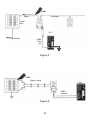
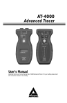
AT-2004-A
AT-2005-A
Advanced Wire Tracer
Users Manual
Advanced Wire Tracer
Users Manual
P/N 2757407 Rev 002
11/2013, 6001566 A
© 2013 Amprobe Test Tools. All rights reserved.
English
AT-2004-A
AT-2005-A
Limited Warranty and Limitation of Liability
Your Amprobe product will be free from defects in material and workmanship for one year from the
date of purchase unless local laws require otherwise. This warranty does not cover fuses, disposable
batteries or damage from accident, neglect, misuse, alteration, contamination, or abnormal
conditions of operation or handling. Resellers are not authorized to extend any other warranty
on the behalf of Amprobe. To obtain service during the warranty period, return the product with
proof of purchase to an authorized Amprobe Service Center or to an Amprobe dealer or distributor.
See Repair Section for details. THIS WARRANTY IS YOUR ONLY REMEDY. ALL OTHER WARRANTIES
- WHETHER EXPRESS, IMPLIED OR STATUTORY - INCLUDING IMPLIED WARRANTIES OF FITNESS
FOR A PARTICULAR PURPOSE OR MERCHANTABILITY, ARE HEREBY DISCLAIMED. MANUFACTURER
SHALL NOT BE LIABLE FOR ANY SPECIAL, INDIRECT, INCIDENTAL OR CONSEQUENTIAL DAMAGES
OR LOSSES, ARISING FROM ANY CAUSE OR THEORY. Since some states or countries do not allow
the exclusion or limitation of an implied warranty or of incidental or consequential damages, this
limitation of liability may not apply to you.
Repair
All Amprobe returned for warranty or non-warranty repair or for calibration should be accompanied
by the following: your name, company’s name, address, telephone number, and proof of purchase.
Additionally, please include a brief description of the problem or the service requested and include
the test leads with the meter. Non-warranty repair or replacement charges should be remitted in the
form of a check, a money order, credit card with expiration date, or a purchase order made payable
to Amprobe.
In-warranty Repairs and Replacement – All Countries
Please read the warranty statement and check your battery before requesting repair. During
the warranty period, any defective test tool can be returned to your Amprobe distributor for an
exchange for the same or like product. Please check the “Where to Buy” section on www.Amprobe.
com for a list of distributors near you. Additionally, in the United States and Canada, in-warranty
repair and replacement units can also be sent to an Amprobe Service Center (see address below).
Non-warranty Repairs and Replacement – United States and Canada
Non-warranty repairs in the United States and Canada should be sent to an Amprobe Service Center. Call
Amprobe or inquire at your point of purchase for current repair and replacement rates.
USA: Canada:
AmprobeAmprobe
Everett, WA 98203 Mississauga, ON L4Z 1X9
Tel: 877-AMPROBE (267-7623) Tel: 905-890-7600
Non-warranty Repairs and Replacement – Europe
European non-warranty units can be replaced by your Amprobe distributor for a nominal charge.
Please check the “Where to Buy” section on www.Amprobe.eu for a list of distributors near you.
Amprobe Europe*
Beha-Amprobe
In den Engematten 14
79286 Glottertal, Germany
Tel.: +49 (0) 7684 8009 - 0
www.Amprobe.eu
*
(Correspondence only – no repair or replacement available from this address. European customers please
contact your distributor.)
AT-2000-A Series
Advanced Wire Tracer
Contents
PRECAUTIONS................................................................................................ 4
INTRODUCTION............................................................................................. 4
AT-2000-A PRODUCT DESCRIPTION.............................................................. 5
COMPONENT DESCRIPTION.......................................................................... 5
R2000 Receiver.......................................................................................... 9
S2600-A Load Signal Generat ors (LSG’s)................................................. 8
T2200 Transmitter................................................................................... 10
APPLICATION NOTES................................................................................... 13
Finding Opens......................................................................................... 13
Finding Ground Faults (See Fig.7).......................................................... 14
Tracing Wires in Conduit (See Fig.8)...................................................... 15
Tracing Energized Wires......................................................................... 16
Tracing Non-energized Lines and Finding Shorts (See Fig.9)............... 16
Locating Individual Wires in a Bundle................................................... 17
Locating Outlets from the Breaker Panel (See Fig.10).......................... 18
Locating Buried Conduit or Metal Pipe (See Fig.11)............................. 18
SPECIFICATIONS........................................................................................... 19
3
Precautions
FOR PERSONAL AND INSTRUMENT PROTECTION
IMPORTANT:
1. Before using any electrical instrument, it should be checked to
make certain it is operating properly.
2. In many instances, you will be working with dangerous levels of
voltages and/or current, therefore, it is important that you avoid
direct contact with any uninsulated, current carrying surfaces.
Appropriate insulated gloves, safety glasses and protective clothing
should be worn.
3. Before attaching anything to the conductor, make sure the voltage
present is not beyond the range of the instrument.
4. When not in use, keep the instrument in its carrying case.
5. When the R2000 or the T2200 will not be used for a period of time,
remove the battery.
Introduction
AMPROBE is dedicated to designing, manufacturing and marketing
high quality, reliable instruments for the skilled professional. The
AMPROBE Advanced Wire Tracer has a history of providing safe,
reliable operation in tracing energized wires, locating circuit breakers,
and locating shorted wires, and tracing non-energized wires, locating
open breakers and locating open wires.
The AT-2000-A Advanced Tracing System combines both Current
Tracing and Open Tracing into one versatile tool providing the ability
to solve virtually all your tracing problems.
Having confidence in an instrument is an important part of using
the instrument. All applications are different and special. An
understanding of the system’s operation could be the difference
between several minutes or several hours on the job.
4
Invest time learning the operation of the Advanced Tracer to build
confidence in the unit. Please read this manual carefully. Take the time
to learn how the instrument operates. Test it in a variety of
situations. You will soon have the confidence to use it on a daily basis
to solve problems which were previously unsolvable.
AT-2000-A series Product Description
The AT-2000-A System consists of different, yet fully compatible
components that are combined into five interchangeable systems:
AT-2004-A Industrial Multipurpose Tracer — includes R2000,
S2600 -A, T2200, and A2201 Clamp-On Accessory.
AT-2005-A Industrial Multipurpose Tracer — includes R2000,
S2600 -A, T2200, A2201, B2024, B2025.
All components are described on the following pages. Each system
contains all necessary cords and accessories.
COMPONENT DESCRIPTION
R2000 Receiver
Has two built in sensors that are tuned to pick up the 32.768khz signals
generated by any of the transmitters in the AT-2000 family: S2600-A,
T2200. The R2000 is designed to indicate the signal’s strength in audio
and visual ways to enable precise location of the conductor carrying
the signal.
Changing Batteries
The battery compartment on the back of the R2000 and the T2200 is a
new design that allows you to drop the battery in and out quickly and
easily. Two holes on the bottom of the compartment accept the round
terminals of a 9 volt battery. Make sure to position battery properly,
otherwise the compartment will not close.
5
1. Mode Adjustment Switch
‘open’ mode is used for
open conductors. ‘SHORT’
mode is used on conductors
that make up a complete
circuit.
5
2. Range Switch Coarse
sensitivity adjustment
3. Battery light Will illuminate
when unit is turned ‘on’
provided the battery is in
place and charged
4. Lanyard Attachment Hole
Attach a wrist strap to
prevent accidental dropping
6
1
2
5. Electromagnetic and
Electrostatic sensors located
in the tip
6. Signal Strength Indicator
10 LED’s positioned behind
a red filter lens to allow
readability in direct sunlight
7
3
7. Sensitivity Adjustment/ONOFF thumbwheel On -Off
switch combined with fine
adjustment of sensitivity
4
8. Battery Compartment
Drop-In-And-Close design
automatically connects
battery with the contacts.
Battery must be oriented
properly to allow it to close.
8
6
Using the R2000 Receiver
1. Turn the R2000 ‘ON’ by rotating the thumbwheel and leave it
around position ‘5’.
2. Move the range switch to x 1 (this is the least sensitive setting).
3. Place the mode switch into the appropriate position and aim the
R2000 properly (see illustration below).
4. If there is no indication on the display. increase the sensitivity by
moving the range switch to x10 or x100. The thumbwheel is used
as a fine adjustment to maintain a midrange indication (3-9 LED’s).
IMPORTANT: Always try to keep the sensitivity low enough to a
maximum of 9 LEDs on the indicator. Otherwise, you could waste
a lot of time determining the proper signal source -- a weak signal
may register 10 LEDs in the x 100 range, but so will a strong signal
(typically the one you want to follow).
5. When tracing, move the R2000 back and forth over the path of the
wire and adjust the sensitivity so that you can see the rise and fall
of the signal level. The strongest signal confirms the path of the
wire.
NOTE: The R2000 will experience electromagnetic saturation when
held up against wires carrying more than 500Amps. If this occurs,
the signal strength indicator will go black. To remedy this, simply
move the R2000 a few inches away from the wire. (See Fig.2) After
the transmitter is connected and operating, but before beginning
to trace wires or circuit breakers, take the receiver and hold it
near the transmitters non-grounded lead, and get familiar with
the double beep pattern that the transmitter emits. When tracing
wires or circuit breakers, that is the pattern to look for. Ignore any
other light and tone patterns that you might see.
7
S2600-A Load Signal Generat ors (LSG’s)
When connected to an energized circuit, the LSG’s will rapidly turn
themselves on and off. This generates a slight, periodic current
fluctuation that causes the power line to emit its own, trace-able
signal. this signal can be detected all the way back to the main
generator. However, the signal will not interfere with any sensitive
electronic equipment and does not require power interruption.
S2600-A- For use on 9 to 300 volts AC or DC circuits only.
1. Power Selection Switch
Use ‘Low’ power when unit is
connected to a GFCI-Protected
circuit.Use ‘High’ power for all
other applications.
2. Connections for Banana Plugs
Are not polarized so it
doesn’t matter which lead
gets connected to power and
which to ground.
3
3. LED Indicator
Light will blink if properly
connected to an energized
circuit.
4
1
4. Intrinsically safe Fuse Holder
Pulling out the fuse holder
automatically disconnects the
fuse from the circuit while
shielding the user from live
terminals.
No Battery!
Units receive power from the
circuit they are connected to
2
8
Both units are intrinsically safe and have a special ‘LOW’ - power
setting used when tracing GFCIprotected circuits.
As their name implies, when connected to a circuit as a load, the LSG’s
cause the power line to generate a signal. The signal will be present
anywhere between the LSG and the power source (‘upstream’ from
the load to the source) - no signal will be present on wiring on the
other side of the LSG (‘downstream’ from the source to the load).
For example, an LSG connected to a circuit breaker will produce no
signal on that circuit. It will, however, cause a signal to be generated
between that panel and the transformer.... and beyond. See Fig.3
NOTE: The signal strength after transformer will decrease according to
its stepdown ratio.
The signal generated is present at all points around the circuit. An LSG
connected to a 110V outlet via the C2901 cordset (throne with the 110V
receptacle) will generate an incoming signal on the neutral wire as well
as an outgoing signal on the hot wire. The close proximity of these two
wires may cause the signals to cancel each other, making it difficult to
trace the cable in these areas (increasing the sensitivity will help detect
the signal). (See Fig.4)
At the panel, the hot wire is separated from the neutral wire (where
it is grounded) allowing easy circuit breaker identification. The C2901
cable is primarily recommended for breaker identification.
Easy tracing of wires and buried cable is accomplished by simply
separating wire from the return path (ground). Instead of using the
neutral wire or the conduit as the ground, use the C2902 Alligator clip
cordset and attach one clip to separate ground such as a water pipe
or a ground rod. A blinking light indicates a completed, functioning
circuit.
Using the S2600-A Load Signal Generators (LSG’S)
1. Make sure the voltage does not exceed the rating of the LSG
2. Always connect the banana plugs to the LSG before connecting to
the circuit. Use the cordset with the 110V plug (C2901) when the
9
task is to identify which 110V breakers control certain receptacles.
Use the alligator clip cordset (C2902) for all other applications.
3. Set power switch to ‘High’ when not tracing GFCI-protected
circuits.
4. Light will blink if circuit is complete and energized.
T2200 Transmitter
TThe T2200 injects a signal onto a conductor. This signal will travel to
the end of a conductor. The T2200 transmitter is primarily used for
finding breaks in hidden or buried conductors. It will also allow you to
trace wires and locate shorts as long as the lines are non-energized.
On an open line, no current will flow, so the injected signal will present
itself as a voltage spike along the wire which is detected by the R2000
in the ‘OPEN’ mode. When the conductor is part of a complete circuit,
the voltage causes a current to flow which produces a signal that is
detected in the ‘SHORT’ mode.
The T2200 contains a 9V battery. A 24V input jack accepts the B2024
rechargeable battery or the B2025 110V converter, both for use when a
very strong signal is needed.
Using the T2200 Transmitter
1. Check to make sure there is no voltage on the conductor you wish
to trace.
2. Using the alligator clip cordset, connect the banana plugs to the
transmitter.
3. Connect one alligator clip to the wire you wish to trace (it doesn’t
matter which one as the input plugs are not polarized) and the
other one to separate ground.
4. Select power level and switch to ‘ON’ - The light should blink.
5. Trace the wire with the R2000 receiver. The signal will stop at the
break in the wire.
10
1
4
5
2
3
6
1. Intrinsically Safe Fuse Holder
Pulling out the fuse holder
automatically disconnects
the fuse from the circuit
while shielding the user
from live terminals.
2. Mode Switch
‘High, ‘MED’, and ‘LOW’
voltage setting used to
match the impedance of the
line.Set at maximum signal
level received on wire.
3. On/Off Switch
Turn ‘OFF’ when not in use.
4. Banana Plug Jacks
Non-polarized
5. ‘ON indicator Light
7
6. 24 Volt Jack
For use with the B2024
battery Pack or the B2025
Converter to boost the
T2200 output.
7. Easy Access Battery
Compartment See ‘Changing
Batteries’, Page 6.
A2201 Clamp-On Transmitter Accessory
Enables the T2200 to induce its signal onto a non-energized or
energized circuit. Plug the A2201 into the T2200 and clamp it around
any conductor in an non-energized circuit, or the hot wire in an
energized circuit. The signal will be induced on top of the 60 Hz
frequency which may be present. The A2201 acts like a 1/2 Volt battery
when clamped around a conductor. On a complete circuit this voltage
will cause about 80mA of additional current to flow through the wire.
11
To increase the signal strength, loop the wire around the clamp a few
times or use the B2024 Battery Pack. The A2201 will allow wire tracing
without the need for direct connection with the bare wire.
Using the A2201 Clamp-on transmitter Accessory
The A2201 will allow non-contact signal indication into energized
or non-energized conductors. On energized lines, the signal will
propagate downstream (from the source to the load) to the end of the
circuit, provided there is current flowing in the circuit. Non-energized
lines must be grounded at both ends or made into a complete circuit.
The signal strength can be boosted significantly by using the B2024
Battery Pack.
One typical application for the A2201 is to access the hot wire at the
panel in order to identify the ‘downstream’ loads:
1. Plug A2201 into T2200. Set mode switch to ‘HIGH’.
2. Clamp the A2201 around the ‘hot’ wire.
3. Set the R2000 to ‘OPEN ‘ mode and trace the downstream wiring.
To trace buried lines, switch to ‘SHORT’ mode.
B2024 BATTERY PACK
24 Volt Nickel-Cadmium rechargeable cell custom designed for light
weight, small size, and durability. Used to boost the output of the
T2200 transmitter: Consult the specs for the boost levels. Includes a
selfresettable fuse. Be sure to charge fully before use.
B2025 110V CONVERTER /RECHARGER
Can be used to either recharge the B2024 or directly boost the T2200.
To recharge the battery , leave it connected for at least 8 hours.
C2901 PIGTAIL - BANANA PLUG CORDSET
For use on 110VAC receptacles.
12
C2902 ALLIGAT OR- CLIP BANANA PLUG CORDSET
For direct contact to bare conductors
APPLICATION NOTES
Finding Opens
‘Opens’ are dead-end conductors that are not connected to anything
and therefore do not pass current. To find an open, use the T2200
transmitter, R2000 Receiver, and the alligator clip cordset. See fig. 6.
1. Verify that there is no voltage on the conductor you wish to trace.
2. Plug the two banana plugs into the T2200.
3. Connect the other alligator clip to a separate ground.
4. Connect the other alligator clip to the conductor.
5. Where possible, ground any other conductors sharing the same
path as the open wire.
6. Set mode switch to ‘LOW’.
7. Turn the R2000 ‘On’ by rotating the thumbwheel.
8. Switch to ‘OPEN’ mode and the x1 sensitivity setting. Note: if the
conductor is buried in moist soil, the ‘SHORT’ mode will give better
results.
9. Move the R2000 down the wire a few feet and adjust the sensitivity
until 5 to 9 LED’s are lit. Move the T2200’s mode switch to ‘MED’
and then ‘HIGH’ and leave it at the setting that causes the
strongest signal on the R2000.
10. Starting from the T2200, trace the conductor. When in the ‘SHORT’
mode, be sure to rotate the R2000 while tracing to maintain proper
orientation in case the wire changes direction. The open will be at
the point you begin to lose the signal.
11. Repeat process starting from the other end of the wire to verify the
location of the open.
13
If you end up tracing the entire length of the wire without locating the
open, you may be experiencing capacitive coupling, or ‘signal bleedoff’ onto the adjacent conductors. This condition may be alleviated
by: a) grounding all adjacent conductors; b) minimizing the distance
between the point of connection and the open.
If another conductor is connected to the first conductor somewhere
along its length, the signal will split between them, causing both
conductors to emit half the signal each. The B2024 battery or the
B2025 converter can be used to increase the signal strength.
Finding Ground Faults (See Fig.7)
A ground fault is a direct connection of the conductor to ground. A
typical ground fault may cause a tripped circuit breaker or a blown
fuse (in contrast to an ‘open’, which passes no current). In this
situation, a battery can be used as the current source. The battery can
be any voltage over 9V, however, higher voltage will be more likely
to overcome a high resistance fault and will produce a stronger signal
(several 9V batteries in series work very well).
Also, you can use line voltage as the power source by connecting the
LSG across the breaker.
1. CPlug the alligator clip cordset into the LSG.
2. Attach faulted wire to battery terminal.
3. Attach another battery terminal to one of the LSG alligator clips.
Connect second LSG alligator clip to Ground.
4. The light on the LSG should blink indicating a complete circuit. If
possible, ground all adjacent conductors.
5. The R2000 receiver can then be used to trace the wire. The signal
should remain relatively constant until you pass the ground fault.
At the fault, the signal from the LSG will pass from the wire and
disperse into the ground. For this reason, the signal strength will
decrease gradually (within 2-3 feet) so you will have to watch the
LED’s carefully in order to get within a few inches.
14
Tracing Wires in Conduit (See Fig.8)
When seeking a ground fault within metal conduit, the ‘ground’ is the
conduit. Connect the battery to the conduit to complete the circuit.
Steel conduit will tend to attenuate the signal strength so tracing
will require higher sensitivity levels and access to within a few feet
of the conduit. Aluminum conduit will severely attenuate the signal
sometimes blocking all the signal from the wire. In this situation, steel
couplings and junction boxes will transmit a signal. It may be necessary
to periodically access the wire in the conduit to confirm signal
presence.
Locating Circuit Breakers or Fuses
Caution: Always check to make sure the line voltage DOES NOT EXCEED
the range of the S2600-A: 9-300V
1. Connect the LSG to the circuit as shown using either the C2901
Pigtail Cordset for 110V receptacles or the C2902 Alligator Clip
Cordset. The light will blink.
2. Turn the Receiver on by rotating the thumbwheel and leave it
around position ‘5’. The battery light should be on.
3. Set range to x 1, and the mode switch to ‘SHORT’.
4. Move the Receiver in front of the outside of each circuit breaker,
as shown, to determine which one has the strongest signal. Use
thumbwheel to reduce the sensitivity when the signal strength
goes above 9 LED’s and leave it in this position until you come
across another breaker with a stronger signal. In this way you can
accurately determine the proper breaker.
5. If two or more breakers produce the same signal strength
indication, remove the panel cover and test each wire, reducing the
sensitivity where necessary.
15
Tracing Energized Wires
1. 1. Connect the alligator clip Cordset to the LSG.
2. Make sure the voltage does not exceed the LSG’s rating.
3. Connect one alligator clip to the hot wire and other to a separate
ground (not something that runs along the same path as the hot
wire). At a receptacle , use the AD-1 Adapter to access the hot wire
and the water pipe or such for the ground, as shown in fig. 3.
4. Starting at the lowest sensitivity setting, x1 , circle the area with
the R2000 in the ‘SHORT’ mode.
5. Increase the sensitivity, if necessary, to locate the path of the wire.
6. Follow the signal path, keeping the sensitivity as low as possible
and adjusting the R2000’s orientation periodically to check for
bends in the wire (See Fig.2).
Tracing Non-energized Lines and Finding Shorts (See Fig.9)
If the wire you wish to trace is part of a complete circuit, or can be
made into a complete circuit easily, use the following procedure. If it is
not part of a complete circuit then use the “Finding Opens” procedure
on page 14.
There are two methods that you can use:
1. A)Connect alligator clip Cordset to LSG.
B) Attach one alligator clip to the wire you wish to trace and the other to one terminal of an AC or DC power source (one or two 9V batteries work fine).
C) Connect the other battery terminal to the other side of your circuit:
a) For line to neutral faults, connect to neutral wire.
b) For grounded wires, connect to a suitable, separate ground.
D) If the LSG blinks, then you have a complete circuit.
E) Turn the R2000 ‘ON’ and switch to ‘SHORT’ mode.
16
F) Trace the wire a) In the case of finding shorts, follow the cable path until you lose all the signal. That will be the location of the short.
b) In all other cases, follow the wire path to its end.
2. A)Connect the alligator clip cordset to the T2200.
B) Attach one clip to one wire and the other to the circuit’s return path (for a line to neutral short, use the neutral wire).
C)Turn the T2200 ‘ON’ and switch to ‘LOW’.
D)Turn the R2000 ‘ON’ and switch to ‘SHORT’ mode.
E) Hold the R2000 near the wire, 2-3 feet from the connection.
F) Adjust the sensitivity to get 3-9 LED’s.
G)Switch the T2200’s mode switch to ‘MED’ and then ‘HIGH’ and leave it at the position that registers the highest reading on the R2000.
H)Trace the wire.
Locating Individual Wires in a Bundle
A. Energized Lines
1. Attach alligator clip Cordset to the LSG.
2. Verify that voltage on the line does not exceed LSG’s rating.
3. Connect one alligator clip to the wire you wish to identify and the
other to a separate ground.
4. Turn R2000 ‘ON’ and leave thumbwheel in position ‘5’.
5. Set mode switch to ‘SHORT’ and sensitivity to x1.
6. At bundle, pull each individual wire away from the other wires and
touch to R2000 tip.
7. The strongest signal indicates the proper wire.
Note: In some instances, capacitive coupling may occur which can
cause other wires to emit the signal, making it difficult to identify
the proper wire. In this situation, switch the LSG to ‘LOW’ and try
again, If this doesn’t work, disconnect power and use a 9V battery
as the power source and attach similar to the ‘ground fault’ set-up.
17
B. Non-energized Lines
Same procedure as “Tracing Non-energized Lines” except, at the
bundle, proceed as in step 6 on previous page.
Locating Outlets from the Breaker Panel (See Fig.10)
If possible, have current flowing in the circuit while tracing. If circuit is
not already in use, plug something in to it.
1. Connect the A2201 Clamp-on to the T2200 Transmitter and then
clamp it around the conductor.
2. Set the T2200 to ‘HIGH’ mode.
3. Set the R2000 to ‘OPEN’ mode, x10 range, and turn thumbwheel to
‘5’.
4. If you do not have the B2024 Battery Pack, increase the sensitivity
to the x100 range.
5. Hold the R2000 in front of each suspected outlet or piece of
equipment. If it is on the same wire as the Clamp, the R2000 will
indicate it.
6. If a known outlet does not produce a signal, increase the sensitivity
on the R2000. If this doesn’t work, check to make sure the battery
is charged.
Locating Buried Conduit or Metal Pipe (See Fig.11)
1. Connect the A2201 Clamp to the T2200 transmitter and then clamp
it around the conduit or pipe.
2. Use the B2024 battery or the B2025 Converter is recommended.
Plug either one into the jack on the side of the T2200.
3. Set the T2200 to ‘higher’ mode.
4. Set the R2000 to ‘short’ mode, x 10 range and turn thumbwheel to 5’.
5. Trace the conduit.
18
Specifications
General
Operating Temperature: 0 to 120° F (-18°C to 49°C)
Storage temperature: -40° to 150° F (-40° to 66°C)
Case material: ABS
Case size: 11”x15” 1/2” x 4” (39.4 x 27.9 x 10.2 cm)
R-2000 Receiver
Detectors:Electromagnetic coil pickup for short mode.
Electrostatic plate pickup for open mode.
Sensitivity Selection: x1, x10, x100 course gain adjustment; 0-10 fine
adjustment.
Short Mode performance: Over 20 feet in air under test conditions
Open Mode Performance: Over 12 feet in air under test conditions
60Hz Rejection: 120db
Power Source: 9V alkaline battery
Display: 10 LED’s with chroma filter lens
Case: Flame retardant ABS 911
Weight: 6.2 oz (176 grms)
S2600-A Load Signal Generator
Operating Voltage: 9-300 volts AC or DC
Operating Frequency: 32.768 KHz
Duty Cycle: Transmits 2 pulses with a duration of 0.0625 each every 0.5
seconds
Current Output —
Low Mode: 35 mA peak, 4mA average
High Mode: 70 mA peak, 6mA average
19
Fuse:Fast acting 250mA @ 660V (6mm x 32mm)
Cat. No. 660.25-6X32
Case: Flame retardant ABS 911
Weight: 3.8 oz (108 grams)
T2200 Transmitter
Operating Frequency: 32.768 KHz
Duty Cycle: Transmits 2 pulses with a duration of 0.0625 each every 0.5
seconds.
Signal Output
High Setting
9V supply
24V supply
1A, 31V
3A 105V
Medium Setting
1.8A, 13V
6A 45V
Low Setting
3.0A, 6.5
10A 22V
Fuse:Fast acting 2A @ 250V 3AG 1/4” x 11/4”
Cat No. No. 2502-6x32
Battery: 9V alkaline- 24V jack will accept battery pack accessory (B2024
or B2025)
Case: Flame retardant ABS 911
Weight: 6.4 oz (182 grams)
A2201 Clamp-on Transmitter Accessory
Operating Frequency:32.768 KHz as supplied by the T2200
Case Breakdown Voltage: 3000 volts
Maximum Wire size: 2000 MCM or 2” dia. cable
Battery: None, power is supplied by T2200
Weight: 9.9 oz (281 grams)
20
B2024 Battery Pack
Type: Nickel-Cadmium Rechargeable (20AA cells)
Capacity: 24Volt, 600 mah
Recharge Time: 14 hours
Fuse: Internal self-resetting
B2025 Recharger/Converter
Input: 115VAC
Output: 24VDC @ 350 mah
21
Figure 1.
Strong Signal
Correct Orientation to wire.
Weak Signal
Incorrect Orientation to Wire
Strong Signal
Turn Receiver to Proper
Orientation
Figure 2.
In the ‘SHORT ‘ mode, orient Receiver so that is perpendicular to the wire.
Example: Horizontal wire — thumbwheel should face up;
Vertical wire — thumbweel should face either left or right.
22
R2000
No Signal
Signal
Panel
Box
LSG
To transformer
C2902
Cord
Set
Figure 3.
R2000
Signals Cancel
LSG
R2901
Cord Set
Figure 4.
23
Tracing Buried Cables
LSG
Hot
To Power Source
Figure 5.
B2
02
4
R2000
T2200
Signal
No Signal
Break
Tracing Open Wire
Figure 6.
24
LSG
Figure 7.
Ground Fault
OR
R2000
LSG
LSG
Figure 8.
identifying circuit Breakers
Hot
Ground
S2600-A
Neutral
Figure 9.
R2000
25
Short to Ground
To Outlets and Equipment
T2200
A2201
B2024
Figure 10.
Tracing Downstream Loads
Figure 11.
Tracing Buried Conduit
B2024
T2200
A2201
26
Visit www.Amprobe.com for
•
•
•
•
Catalog
Application notes
Product specifications
User manuals
Amprobe®
www.Amprobe.com
[email protected]
Everett, WA 98203
Tel: 877-AMPROBE (267-7623)
Amprobe® Europe
Beha-Amprobe
In den Engematten 14
79286 Glottertal, Germany
Tel.: +49 (0) 7684 8009 - 0
Please
Recycle