1
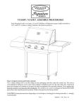
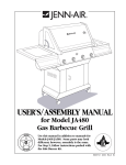
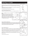
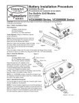
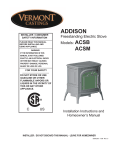
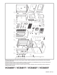
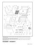
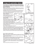
Gas Conversion Procedures
VCS3008, VCS4008, VCS5008 Series Models
CAUTION: ANY GAS CONVERSIONS MUST ONLY BE
PERFORMED BY QUALIFIED PERSONNEL
These instructions cover all 2008 models for conversion
to either gas. Ensure the valves and orifices you are
installing match the specifications in Table 1 for the gas
you are converting to.
Adjust the air shutters of the burners according to Table 2.
IMPORTANT: DISCONNECT GAS SUPPLY BEFORE
CONVERTING ANY GRILL
1. Open grill lid, remove the cooking grates and sear
plates from the grill.
2. Open side burner lid, detach valve control knob from
the valve stem.
3. Remove two (2) screws mounting side burner valve
to side burner base (support valve/hose assembly
from damage or causing damage to any part of the
grill).
4. Detach valve bracket from side burner valve by
removing two (2) screws.
5. From under the side burner, disconnect igniter wire
from the side burner electrode.
6. Detach left shelf assembly from the grill (models with
rotisserie burner require detaching rotisserie motor
bracket).
7. Detach right shelf assembly from the grill.
8. Detach all knobs from console.
9. Remove all screws (2 screws/valve) connecting bezels and valves to the console (do not detach bezels
from harness).
10.Remove all screws connecting console to the grill.
The console can now be tilted upwards and detached from grill to access the valve assembly (take
care not to damage the harness).
11. Detach hose clamp located at right door hinge (for
4008 series detach hose bracket located at right side
door brace).
12.For models with rotisserie burners, loosen the compression nut of the rotisserie burner supply tube (to
the top valve), and disconnect the tube by pulling it
straight out from the valve.
13.Carefully disengage valve/manifold assembly from
main burners and remove valve/manifold assembly
with attached gas line/side burner valve from the grill
(side burner valve needs to be moved through right
side panel provided opening).
14.Engage the new valve/manifold assembly to main
burners and feed the supplied hose with side burner
valve through the right side panel provided opening.
For models with the rotisserie burners, reattach the
rotisserie burner feed tube to the top valve.
15.Install previously removed hose clamp on gas line
and secure gas line to the grill cabinet by reattaching
hose clamp to original location (for 4008 series reattach hose bracket located at right side door brace).
16.Reattach the console (with harness and all bezels)
to the grill. Make sure the harness is not pinched
in any place and the valve assembly is properly
engaged into main burners. Loosely attach all valves
to the console using the bottom screws first, and
then loosely attach all bezels to the valves with top
screws. Reinstall all mounting screws to secure
console to grill. Now tighten all screws previously
attached to all valves.
17.Ensure the burner venturi ends fit over the ends (gas
tips) of the main valves.
18.For models with rotisserie burner, replace orifice cap
for the rotisserie burner as follows:
Remove all upper panel mounting screws. Remove
upper back panel. Remove “hair pin” connecting orifice with rotisserie burner venturi. Disengage orifice
from rotisserie burner venturi. Remove and replace
orifice cap, reinstall orifice to rotisserie burner
venturi. Reinstall “hair pin” connecting orifice with
rotisserie burner venturi. Reinstall rear panel and
secure it with screws.
19.Reattach all knobs. Place the long stem knobs in the
center raised portion of the console.
20.Reattach left shelf assembly to the grill (for models with rotisserie burner, reattach rotisserie motor
bracket).
21.Reattach right shelf assembly to the grill.
22.Attach new side burner valve to valve bracket with
two (2) screws.
23.From under the side burner assembly, position and
align valve/bracket assembly to side burner venturi
and reattach valve/ bracket assembly to side burner
base, ensuring the gas tip of the valve extends into
the burner venturi. Reattach valve control knob to
the valve stem.
24.From under the side burner, reconnect igniter wire to
side burner electrode.
25.When converting to LP, it is necessary to remove the
cover plate in the bottom panel (by removing four
(4) screws) to allow the LP cylinder to be positioned
properly. Apply Caution Label to the right door-below
label lighting instructions. Attach the cylinder retainer
bracket to the inside of the back panel (by snappingin retainer bracket into provided “lance and form”
50004918 1/08 Rev. 0
openings. (If Pull out Tank Kit is purchased (part
# 50004650), install it according to the assembly
procedure supplied within the kit). Follow Assembly
Procedures for LP tank installation.
26.When converting to NG (NATURAL GAS PRESSURE@ 7 IN. WC), it is necessary to install provided
bushing into back panel opening and run natural
gas hose through it. Cover for cylinder opening with
hardware is provided if customer requires covering
this opening. (For some models removal of Pull out
Tank assembly is necessary to cover cylinder opening).
27.Replace the cooking grates and sear plates to the
grill.
28.Apply new gas type sticker at the left- bottom
corner, beside rating decal at the rear of the grill.
Do not apply over any existing label.
Valve/Orifice
Type
Main Manifold/Valve
37,500 BTU
Main Manifold/Valve
50,000 BTU
Main Manifold/Valve
62,500 BTU
Side Burner
15,000 BTU
Rotisserie Orifice
15,000 BTU
Rotisserie Orifice
20,000 BTU
Grill
Model
VCS3008
Series
VCS4008
Series
VCS5008
Series
All
VCS Models
VCS4008
Series
VCS5008
Series
Part #
50004136
Table 1
Natural
Color
Gold Cap
50004140
Gold Cap
50004142
Gold Cap
50001045
Gold Cap
50000408
Red Stripe
50004917
Red Stripe
Table 2
Air Shutter Opening Chart - Convertsion Kit
Burner
Air Shutter Opening
Main Burner
3/16” (4.75 mm)
Rotisserie Burner
25/64” (10 mm)
Side Burner
9/16” (14 mm)
2
29.Leak Check: Attach the new hose or regulator to the
appropriate gas supply. Confirm all burner control
knobs are OFF. Open the gas (cylinder) supply
valve. Apply a 50/50 mix of liquid soap with a brush
or spray bottle to all connection points. Never use a
match or flame. Look for any bubbles to appear, as
these indicate a gas leak. Turn off the gas immediately, and tighten the connection, if a leak appears.
Repeat this step until no leaks appear, before lighting the grill.
30.Finally, fire test all burners with the new gas. Small
adjustments to the air shutters may be required for
proper lighting, and flame characteristics
ID#
#53
(0.0595)
#53
(0.0595)
#53
(0.0595)
#52
(0.0635)
#51
(0.0670)
#46
(0.0810)
Part#
50004134
Propane
Color
Black Cap
50004139
Black Cap
50004141
Black Cap
50001046
Black Cap
50000457
n/a
50000714
n/a
ID#
#60
(0.040)
#60
(0.040)
#60
(0.040)
#57
(0.0430)
1.15 mm
(0.0453)
1.30 mm
(0.0512)
Refer to User’s Manual (CFM #50004581) for additional
safety instructions after conversion. Always keep this
instruction with the User’s Manual for future reference.
50004918
Kit Specification Chart
Kit #
50004689
LP to NG
Model
VCS5008
Series
Input BTU’s
Main Burner
62,500
Accessories
35,000
50004690
NG to LP
VCS5008
Series
Main Burner
62,500
Accessories
35,000
50004691
VCS4008
Main Burner
50,000
Accessories
30,000
50004692
NG to LP
VCS4008
Series
Main Burner
50,000
Accessories
30,000
50004918
Specification
1 x Valve/Manifold Assembly NG (Part #50004142)
1 x Connector Hose (Part #50000920)
1 x Natural Gas Hose 12’ Long (Part #50002384)
1 x Valve Side Burner NG (Part #50001045)
1 x Orifice Cap #46-Rotisserie (Part #50004917)
1 x Cover Plate (Part #50004260)
4 x Screw (Part #50004268)
1 x Snap Bushing (Part #50002490)
1 x Instruction Conversion Kit (Part #50004918)
2 x Label Conversion Kit to NG (Part #50004983)
1 x User Manual VCS Series (Part #50004581)
1 x Valve/Manifold Assembly LP (Part #50004141)
1 x Hose Regulator (Part #50003815)
1 x Valve Side Burner LP (Part #50001046)
1 x Orifice Cap # 1.30 mm-Rotisserie (Part #50000714)
1 x Cylinder Retainer (Part #50002888)
1 x Instruction Conversion Kit (Part #50004918)
2 x Label Caution - LP Cylinder (Part #50000159)
1 x Label Conversion Kit to LP (Part #50004984)
1 x User Manual VCS Series (Part #50004581)
1 x Valve/Manifold Assembly (Part #50004140)
1 x Connector Hose (Part #50000920)
1 x Natural Gas Hose 12’ Long (Part #50002384)
1 x Bracket Support Hose (Part # 50004276)
1 x Valve Side Burner NG (Part #50001045)
1 x Orifice Cap # 51-Rotisserie (Part #50000408)
1 x Cover Plate (Part #50004260)
4 x Screw (Part #50004268)
1 x Snap Bushing (Part #50002490)
1 x Instruction Conversion Kit (Part #50004918)
1 x Label Conversion Kit to NG (Part #50004983)
1 x User Manual VCS Series (Part #50004581)
1 x Valve/Manifold Assembly (Part #50004139)
1 x Hose Regulator (Part #50003815)
1 x Valve Side Burner LP (Part #50001046)
1 x Orifice Cap # 1.15 mm - Rotisserie (Part #50000457)
1 x Cylinder Retainer (Part #50002888)
1 x Instruction Conversion Kit (Part #50004918)
1 x Label Caution - LP Cylinder (Part #50000159)
1 x Label Converion Kit to LP (Part #50004984)
1 x User Manual VCS Series (Part #50004581)
3
Kit Specification Chart
Kit #
50004693
LP to NG
Model
VCS3008
Series
Input BTU’s
Main Burner
37,500
Accessories
15,000
50004694
NG to LP
VCS3008
Series
Main Burner
37,500
Accessories
15,000
Specification
1 x Valve/Manifold Assembly (Part #50004136)
1 x Connector Hose (Part #50000920)
1 x Natural Gas Hose 12’ Long (Part #50002384)
1 x Valve Side Burner NG (Part #50001045)
1 x Cover Plate (Part #50004260)
4 x Screw (Part #50004268)
1 x Snap Bushing (Part #50002490)
1 x Instruction Conversion Kit (Part #50004918)
1 x Label Conversion Kit to NG (Part #50004983)
1 x User Manual VCS Series (Part #50004581)
1 x Valve/Manifold Assembly LP (Part #50004134)
1 x Hose Regulator (Part #50003815)
1 x Valve Side Burner LP (Part #50001046)
1 x Cylinder Retainer (Part #50002888)
1 x Instruction Conversion Kit (Part #50004918)
1 x Label Caution - LP Cylinder (Part #50000159)
1 x Label Conversion Kit to LP (Part #50004984)
1 x User Manual VCS Series (Part #50004581)
CFM Corporation
2695 Meadowvale Blvd. • Mississauga, Ontario, Canada L5N 8A3
800-668-5323 • www.cfmcorp.com
4
50004918