1
R.esearch
report
115
-t
A
HETEROGENEOUS PYRAMID ARRAY
ARCHITECTURE FOR IMAGE
U
N DE RSTAN
DING
Rolf Holorth
(RRr r s)
Abstrqct
This paper describes a massively parallel architecture for image understanding and computer
these applications is the transition from iconi. tJ*or" abstract
symbolic data representations. A heterogeneous pyramidal array of processors matches the
structure of the problem well. The architecture we are considering ionsists of a fine grain
multi-SIMD array of bit-serial associative processors for low-levet pixet operations and a
larger grain transputer array for high-level symbolic processing. An interm"diut" processing
layer between these plays a vital part in reducing the bandwidth of vertical communication
vision. A key issue in
and controlling the bottom level, allowing parts of what would otherwise be a
straightforward SIMD array to operate independently. Systems issues such as how to
program the different levels are discussed, and a simulator of the architecture is briefly
described.
Departrnent of Computer Science
University of Warwick
Coventry Cv47AL
United Kingdom
December 1987
A Heterogeneous Pyramid Array Architecture
for Image Understanding
Rolf Howarth
Department of Computer Science
Universin of Warwick
1.
Introduction
\
We have been investigating the design and application of dedicated VLSI arrays to image understanding and computer vision.
Computer image understanding will typicaily consist of processing multiple 5I2x5l2 arrays of
pixels representing image intensities as input and producing a high-level abstract description of
the scene as output, in real time.
The difficulty in building a machine to do this processing is that a wide variety of operations
needs to be performed, on very different representations of the data, and that any architecture
which may be good at one type of operation (eg. pixel-based iconic) is likely to be unsuited to
other types (such as possibly list-based, symbolic representations).
For the initial pixel array (or iconic) representation, and the corresponding class of operations
such as thresholding, convolutions, and histogramming that one wishes to perform on this data, it
seems clear that an array of arithmetic processors is most suitable. A high degree of parallelism
is necessary to handle the throughput of such a large amount of data. About 10 million pixels
need to be processed per second for real time applications, and the throughput is particularly
large when one considers that even for a simple linear operation such as a 5x5 convolution 25
multiplications and accumulates are required per pi*91. For non-linear operations such as
median flltering the throughput requirement grows as N', and of the order of 1,000 MOPS may
be needed. Many such machirles, mostly consisting of relatively simple SIMD (single instruction
stream, multiple data stream) a:ray processors, have been built (for example CLIP, DAP, GRID
etc. [Duff78,Hunt8 1,Pass85]).
These machines are only really suited for low-level iconic processing however. We are
interested in the problem of how to abstract from iconic to symbolic level data representations,
or, in other words, how to move from a quantitative to a qualitative description. We believe that
a hybrid architecture, with different types of processing element for different aspects of the computation, will be essentiai for this kind of abstraction process.
The Warwick Hierarchical hnage and Signal Processor, or WHISP, is one such architecture
which is currently under deveiopment at the University of Warwick. Work is progressing in the
use of transputer arrays for higher level processing, and a software simulator of the lower levels
of the proposed architecture has been written and is being used to help clarify cerain issues in
the design. Detailed designs for the processor cells are in preparation and we hope to be able to
commence work on building a prototype machine in the near future.
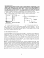
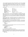
2. Pyramid Architecture
The architecture we are working with has the form of a non-homogeneous pyramidal array of
processors, with a very fine grain array, one per pixel, of numeric processing elements similar to
a CLIP or DAP, under the control of a system of more powerful MIMD (multiple instruction
stream, mulriple data stream) processors (fi7. I). The machine we are designing will be a special
purpose peripheral device attached to a conventional host computer providing file store etc., and
together they form a complete image processing system. An image to be processed may either
be downloaded from the host, or directly into the pixel array if a camera is included in the system.
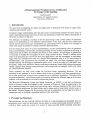
Host Machine
eg. Sun workstation with graphics
Symbolic Processing Layer
4x4 MIMD machine using transputen
Intermediate Processing Layer
16x16
MIMD processors, controlling PPELs
Iconic Layer
256x256 SIMD bit-serial associative PPELs
Fig.
I
Warwick Hierarchical Image and Signal Processor
Four layers of processors are included in the pyramid. At each levei the granularity and type of
processor is chosen to best match the structure of the data and the types of operation to be performed on it.
By including some associativc capability at the pixel level together with its bit seriai arithmetic
we are able to extract the required computed features and perform the first step of iconic to symbolic nansformation. Each Intermediate Layer Processor acts as a controller for the 16x16 pixel
processors below it, and passes data calculated over this region (such as a histogram of intensities, the area of shapes, or other image features) to the Symbolic or Higher Level Processors
above it. These, while responsible for direct communication with the Intermediate Processors in
the corresponding region below, are mainly working on more abstract data, such as objects, their
attributes, and relations to each other, rather than divisions of the image into physical regions.
2.1. Iconic Layer
This layer is intended to perform the low level pixel processing, such as finding maximum intensities, performing convolutions etc. An array of bit-serial processors with four- or eight-way
interconnection, one per pixel, has been shown to be an effective solution for this [Duff86], and
one which it is feasible to implement in WSI.
The advantage of bit serial processors over, for example, an 8-bit processor, is that the design of
the ALU stays relatively simple, and it is possible to replicate many such processors on one chip,
making it practical to have a processor for each pixel in the image. Also, there is no unused silicon being wasted when purely binary as opposed to multi-bit grey-level images are being processed, and because the carry only has to be propagated by one bit each cycle instead of by eight,
the cycle time can be shorter (rhis means that eight l-bit processors may be able to perform eight
8-bit operations faster than one 8-bit processor can, although in both cases eight cycles are
needed). [see, for exampie, Hillis, 3.1].
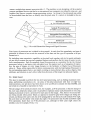
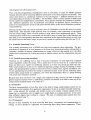
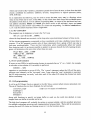
The block diagram of a WHISP Pixel Processing Element (PPEL) is shown infig.2. Each PPEL
has a bit-serial ALU, with 7 flag bits and 256 bits of general purpose memory. The basic operation of the PPELs is quite straightforward. In each insffuction cycle two source operand bits
(from the flags, from main mernory, or from a neighbouring PPEL) together with the accumulator
flag F are read into the ALU, combined by some logical function, and two result bits written out,
one back to the flag and one to an arbitrary destination. This operation is performed by all active
PPELs concurently.
address
(7)
nearest
neigh.fuiur
i select
(4) j select (4)
inputs (8)
function code (16)
source data (16)
shif ow
shifi in
shifi clk
Fig.2
PPEL ceil diagram
The PPELs operate in SIMD rnode (each processor executing the same instruction but on different data), with instructions broadcast over the array on a common bus. The PPELs are connected in a mesh with 8-way nearest neighbour connectivity. To facilitate reading data into and
out of the array the PPELs are wired together as a long shift register, as well as being connected
on a grid of addressing lines with an open collector wired-OR response capability (see 2.2).
2.1.1 PPEL memory
The organization of the PPEL rnemory, consisting of some flags and a main register file, is shown
in table 1. It may seem that 256 bits is a reiatively large amount of main memory for a simple
processor, but the overhead of extra silicon necessary for the RAM and address decoding in proportion ro rhe area of silicon devoted to the ALU is justified by the increase in speed due to elimination of the need to access off-chip RAM.f
The memory is organized as two 128-bit register files, with a shared address decoder. This
somewhat unusual system was chosen as a compromise, able to perform the very common subclass of operations having just two operands, one of which is a combined source and destination,
faster than a single address machine, but without the extra silicon needed by a two or three
t
A similar design decision was nrade for the Inmos transputer.
X
Y
Z
T
A
PO
PI
Y2
P3
...
Q0 Q1
Q2
Q3
I
F
P
r27
a
t27
X
Output bit; passes results to neighbouring PPELs and to the open collector response
circuitry.
F
Flag bit; carries over results during multi-bit operations.
Y,Z,T
Spare bits; used for intermediate results.
A
Active bit; if the condition bit is set in the opcode then only those processors whose
active bit is set perform the operation, otherwise A may be used as another generai
purpose bit.
I
Input/output bit; pmt of the fast shift register chain.
P,Q
Two general purpose 128-bit register files.
Table
1 PPEL flags and registers
address machine. Clearly it is not as powerful as the latter because some operations (such as
copying) may have to use one of the flag bits as a temporary variable and take an exffa cycle per
bit, but it introduces a significant saving in terms of silicon area used, for the alternative would
be to increase the instruction word size and have separate decoders for the destination and each
source operand in an operation. For any given address, the P and Q bits may be freely selected
as source and/or destination in an operation.
Notwithstanding the above consideration, user programs can regard the memory as being arbitrarily split up into variable sized arrays of bits (it may be used as a collection of 8-bit grey-scale
images, binary images, and intermediate arithmetical results, for example).
2.
1.2 PPEL instructions
The length of a PPEL instruction word is 35 bits, which may be broken down into six fields
shown in table 2.
function code
src I
I
t6
src
A
A
/
dest
J
as
address
7
.
.
16-bit ALU function opcode
Conditional execution bit c, used in conjunction with the 'A' flag
o Source i, j and destination doperand addresses (3 or 4 bits each)
o Shared address for P and Q register files (7 bits)
Table
2
PPEL instruction word
2.1.3 Function opcode
The ALU can perform any of the 216 logic functions mapping three input bits (two arbitrary
sources i and j, plus F) to two oulput bits (one arbitrary destination d, plus F). The ALU is simply a boolean function generator, implemented by a dual 8-to-1 multiplexer, with the truth table
of the function to be carried out as input and the three input bits as selector. The function
4
opcode therefore has 16 bits (2 output bits for each of 8 different inputs).
For example, the code for the'add with carry'function is 0001011001101011, which may be
calculated by reading successive pairs out of the last two columns in the truth table below.
Input
Fit
UUU
001
010
0li
100
101
110
1ll
Tuble
-l
i+j+F
F'd
UU
01
10
01
l0
10
1t
0r
Truth table for'add with carry'
By making use of the flag bit it is possible to perform simple multi-bit operations such as addition at the rate of one bit per instruction cycle.
2.1.4 Operand sub-field
Each of the argument sub-fields specifies either one of the 6 flag bits, a value from one of the
two register files, or the oufput from an adjacent PPEL (table 4). The destination address only
needs to be 3 bits long, because the inputs from neighbouring PPELs are read only.
0000 M01 0010 0011 0100 0101 0110 0111 1000 t00I 1010 10lI 1100 1101 1110 1111
E
w NW
sw
I
N
NE
SE
s
A
P
T
Y
Z
X
a
Table
4
Ooerand address codes
2.1.5 Examples
A complete opcode is formed by combining these various fields, for example
0001011001101011 0 0100 0001 101 0001001 = 'ADC uncond P Y Q 17'
adds together P17 and Y plus the carry flag F, writing the result into Q17 and setting the carry
flag as appropriate (F,Q17 e P17+Y+F). The corresponding progmm fragment in the interpreted WHISP language would simply be " ADC P Y Q 17 " (see section 3). Similarly
0001010110111111 1 1101 0000 ClO 0000000 = 'OR cond SW xZ}'
or's the X bit of each active PPEL (ie. all those whose A flag is set) with that of its neighbour to
the south-west, storing the result inZ (if A then Z e- SW v X).
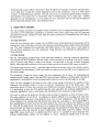
2.2. PPELfiLP Communication
In the WHISP pyramid the iconic and intermediate processing layers are very closely coupled.
The PPELs are grouped together in clusters (fig.3), each consisting of 16x16 PPELs, with an
associated Intermediate Layer Processor (tr-P). Because of their simplicity, it is possible to make
the PPELs instruction cycle very short, and a fast micro-controller is needed to sequence the
instructions. The function of an ILP is both to act as a microcontroller for the PPELs in the cluster, and to collate information over that cluster, thus helping to collapse the pyramid and reduce
the bandwidth of vertical comrnunication between levels. The ILP processing layer forms a vital
part of the overall pyramid machine, because a major bottleneck would occur if a transputer
array, say, which is unsuited to handling a large volume of simple data, were to be directiy connected to a large number of PPELs.
IntJrmediate Level
Processors
16x16 cluster of PPELs
under each tr-P
Fig.3 A cluster of PPELs
We are curently investigating two systems for passing data to and from the PPEL array.
2. 2.
1 Sequential access
one bit per PPEL runs through the cluster (all the I/O bits are chained
together) and may be used to rapidly load data, including the initial input from a video camera
(though for this it would be preferable to have the chain running in rows across the whole image
rather than in clusters, and to read data fast enough we will probably need some buffering at the
start of the scan iine and read in several lines in parallel). ln addition, the shift register output is
fed into an accumulator so instead of a normal PPEL instruction cycle an ILP may initiate a fast
shift cycle to count how many PPELs in the ciuster are in a certain state.i One might also give
the ILPs direct access to the output of the shift register, so to read data out the PPEL array one
could shift data from the entire ciuster into tLP memory and then use direct addressing. The
maximum shift rate will be around 20 MHz, so reading in 16x16x8 bits would take 100ps. This
method is most suitable for reading in calculated values, such as variances or intensities to be
averaged or histogrammed sav, rather than finding the positions of particular points.
A shift register with
Each PPEL also has an open collector buffer on the X-bit driving a cornmon bus, which provides
a wired-OR some/none response capability. Any PPEL can pull this line low, and the controlling
ILp can instantly detect whether any or none PPELs in the cluster are responding. This enables
the a:ray to be used as an associative or content addressable memory, with only a small amount
of computation necessary to perform a comparison over the whole turay.
The wired-OR circuit can also be used to read data out of a PPEL bit-serialiy, but only if exactly
one PPEL is tagged as being active. This could be used to read the address of a responding
PPEL, but if there is more than one PPEL whose position one wants, some method of stepping
through them is necessary, for example by chain coding the points forming an edge and tagging
successive points to get them to output their position.
t
The cEC GRID processor uses a similar method to accumulate responses, and Ian Page's
Disputer uses a shift register chain to load images.
2.2.2 Random access
Since identifying the positions of points is a fairly cornmon operation, it may be useful to have
wired-OR lines along all the rows and columns, with an encoder at the two edges enabling one to
tell the position of a responding pixel directly (fi7.4). If one left out the encoders and gave the
ILPs direct access to the lines one would have increased flexibility (for example one could easily
establish whether more than one PPEL is responding, and could read 16 bits from an enti-re row
or column at a time), at the expense of having to do the 16 to 4 encoding in software.
In addition if the wires are bidirectional, this mesh can be ur.i ,o allow the ILP to directly
address an individual PPEL or group of PPELs, turning the cluster into a RAM (7i9. 5).
V
address
Active low address bus mesh
H address
Fig.4
Position detection within cluster
Fig.5
PPEL gating onto address bus
If
we use this system it wili be incorporated into the PPEL design by making the A flag write
only and replacing its output onto the source bus with the 'PPEL active' oulput below. The lines
are bidirectional and are nomrally driven by the PPELs (ie. 'Assert address' is active) except
when they are reading the 'PPEL active' data.
2.3. Intermediate Processing Layer
A functional diagram of an ILP element is shown in fig.6. The processor itself is likely to be
implemented with bit-slice and programmable logic, though a fast conventional off-the-shelf
microprocessor could also be used. Each ILP has 16K or 64K of progrrlm and data RAM. This
memory is dual ported between the ILP and the Higher Level Processor above it, which places
instructions in the RAM and in this way conffols the ILP. The ILP controls the PPELs in the cluster using a fast progmrnmable instruction sequencer. This is necessary because the PPEL instruction cycie is so short (around 100 ns) that the ILP would be unable to supply PPEL instructions
fast enough to keep the PPELs busy otherwise.
Building a custom ILP processor is convenient from a software standpoint because PPEL operations can be wired in directly as part of the ILPs assembler instruction set. This point is worth
elaborating a little. Since a cluster consists of several ALUs and memories (the ILP itself and all
the PPELs) but only one element controlling the flow of execution, it is a question of definition
whether a cluster should be viewed as a single 'processor' or several. Though, in a sense, the
PPELs are separate processors, it is better to think of the PPEL array as being a co-processor to
the ILP since the ILP is in overall control. Together the ILP and the PPELs form a single programmable unit (see 3.1), and it is convenient if this is reflected in the assembly language.
I6KRAM
DuaJ-ported
(kograrn/Data)
PPEL cluster
Fig.6
Cluster block diagram
2.3.1 ILP operation
On powering up or when an ILP is reset by its controlling Higher Levei Processor, a program is
downloaded into the ILP RAM. The program usually consists of a number of small sub-routines,
each of which is called up by the HLPs through pre-defined entry points to perform one particular operation such as thresholding, although there is nothing to stop a complete application being
run on the ILPs.
The ILPs are prograrnmed in rnicroprocessor assembly language, with some additional instructions to access the PPELs. Basic PPEL operations may be broadcast directly to the cluster,
bypassing the microcontroller, multi-bit PPEL macros may be used, or certain global cluster
operations can be performed.
Multi-bit PPEL operations are carried out using the microcontroller to generate a sequence of
PPEL instructions. A micro-code program is in effect just a list of PPEL instmctions, and an
operation is initiated by loading the microcontroller with the starting address of a micro-code
subroutine or function. The ciefinitions for these functions are either taken from PROM or programmed into the micro-controlier RAM by the ILPs at boot time.
In addition to the basic SIMD operation of the PPELs as described in 2.1, there are certain operations which take effect over the whole cluster. The ILP has access to the wired-OR function over
the cluster and this may be used in a conditionai construct (the statement is executed if some
condition holds for one or more element in the may). By clearing the accumulator and then initiating a shift cycle the ILP can count the number of responding PPELs in the cluster. The ILP
can read in two 16-bit row and column masks (with an entry of 1 if there is a responding PPEL in
that roVcolumn, or 0 if not) to identify responders, or it can set bits in the row and column
masks to mask a block of ppgLs and restrict an operation to just these PPELS.
2.3.2 SIMD versus MIMD
Though the ILP layer is a mesh-connected MIMD machine, it is usually regarded as a broadcast
SIMD machine, essentially similar to PPELs, but with much higher level functionaiity and programmability (its 'instructions' would be at the level of 'calculate a histogram', for example).
Potentially a separate progranr could be compiled and run on each ILP independently, but there
are great difficulties involved in expressing such programs and it is much simpler to duplicate
one program over all the processors.
Even with this programming simplification, there is still plenty of scope for MIMD operation
because the ILPs can be execudng different instructions in the same progrilm concurrently. This
different branches are exearises when there is a conditional statement in the ILP program
a
cluster
operate in SIMD mode
PPEts
within
All
the
in
PPELs.
the
data
on
the
cuted depending
but the clusters are independently controllable, which greatly increases the potential for parallelism. Different operations may be performed concurrently on different regions (assuming no
pixel-level communication needs to take piace between them, as this would introduce synchronisation problems).
Having said this, there will still be occasions when it is desirable to run the ILP array in a purely
SIMD mode. This situation might typically arise, for example, when calculating a convolution
over the whole image, which involves reading in data values from neighbouring pixels. These
communications need to be synchronised (all the PPELs have to output data in one direction and
then read in the corresponding data from their neighbour in the opposite direction), not only over
the cluster but over the entire image, so provision is made for synchronising the ILPs (see 3.1.4).
2.4. Symbolic Processing La1'er
The symboiic processing layer in WHISP runs high level computer vision algorithms. The general mode of operation is to send requests to the lower level numeric processors asking them to
calculate a number of features characterising an image, which are then passed up to the HLPs
(higher level processors) for further processing to identify objects and the relationships between
them.
2. 4. 1
Symbolic processing paradigms
Currently we are suffering from a lack of practical experience of such high-level computer
vision algorithms within the group. This is paniy due to the fact that this is a relatively new
field, and there are a number of conflicting opinions as to how one should go about this task.
While some people are in favour of a traditional approach, perhaps starting by filtering to detect
edges, then grouping these together at successive levels to obtain lines, regions and objects, others are approaching the problem by trying to understand human vision and are modelling many
of their ideas using neural net computers, and within this deparrnent there is a group working
with novel multi-resolution methods.
Because there does not seem to be a single clear approach to take, the aim has been to design a
general purpose machine which is sufficiently powerful and flexible to be able to meet any of the
computational demands likely to be made of it.
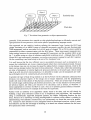
2.4.2 Dataflow
The basic communication or data flow issue in the kind of image understanding system we are
considering is the nansition from geometric organisation of data to an object oriented representation. A line segment, for example, will initially consist of a number of pixels spread over the
image, but we eventually want to regard it as a single object on a single processor. At the same
time, different objects may overlap in a region. The type of communication pattern that may
arise is illustrated infig.7.
2.4.3 Transputers
Because of their suitability for tasks involving both heavy computation and communication or
routing, we have decided to implement this processing layer using Inmos transputers. These
Symbolic data
Pixel data
Fig.7 Transition
from geometric to object representation
powerful 32-bit processors have special on-chip scheduling hardware to efficiently execute multiple processes on one processor, and run the parallel programming language occam.
One approach we are studying involves splitting the transputer layer, having the HLP layer
proper consisting of an MIMD system of powerful processors, possibly the new floating point
T800 ffansputers, and an associated 4x4 or 8x8 array of cheaper T2s or T414s which would be
responsible for direct communication with the ILPs below. These interconnect transputers perform routing between the geometrically arranged ne processors and the symbolic HLPs as per
fig.7, in effect acting as a type of software-controllable switching circuit. Although there will be
several ILPs per interconnect transputer, we can have one process running for each ILP, responsible for controlling it and interfacing to the rest of the transputer layer.
processors such as transputers is to
ensure that calcuiations are always compute-bound rather than communication-bound, because
in the former case one can increase the speed by adding further compute elements, while in the
latter one has already reached the limit for that architecture. Clearly then, rather than connecting
an array of transputers or similar high-level processors directly to the pixel layer, which would
ciog it up with low-level comrnunications, it is desirable to make sure the transputers are working with higher-level (ie. compressed, pre-processed) data.
It is well known that the most efficient way to use parallel
In general the type of data being worked on at the HLP level will be sufficiently abstracted that
divisions into physical regions of the image are no longer important, and the programming
model will tend to hide details of the physical connectivity. There are several ways of dividing
the overall image understanding task between processors, and we may decide to run one process
per physical region, per object, per function to be calculated, such as texture, or whatever. It
seems appropriate to connect the HLPs in such a way as to optimise general arbitrary communication between processors, for example in the form of a hypercube.
Further work on symbolic level algorithms clearly needs to be done, and we will shortly be
building a large iuray transputer system to try to implement some algorithms. We considered
using a commercially supported transputer product, the Meiko Computing Surface, for this
array, because of its advantage of being reconfigurable in software which makes it suitable for
experimenting with different connectivities, but unfortunately we found the cost to be prohibitive. Instead we have decided to use a transputer board we developed ourselves, which is more
cost-effective and has the advantage of enabling us to attach our custom hardware for the lower
level processors more conveniently.
10
2.5. Host Machine
The apex of the WHISP pyramid will consist of a single machine which performs almost no
image processing of its own but asks questions of the pyramid below it, accepts an answer from
the pyramid, and decides what action to take as result. The ilost machine is responsible for providing mass storage and downloading proglams into each processor, and also provides the user
environment, such as editors and debuggers for developing progams to be run on the lower levels, displaying intermediate results, and so on.
machine such as a Sun workstation would seem appropriate, since it combines a powerful
development environment with a suitable graphics capability to display results, but since the
Transputer Development System software is not yet available for the Sun we will initially be
using our microVax running VMS. In the proposed system one transputer of the HLP array
resides on a VME card in the nfcroVax and acts as interface between the host and the other tran-
A
sputers.
In a 'production' embedded system some of the host's tasks might be handled by the rest of the
system (eg. shop floor control computer), but a single processor would still need to be present at
the top of the pyramid as the interface point.
3. Programming WHISP
Because of its heterogeneous nature WHISP is programmed at two distinct levels: the ILP clusters
are programmed in microcode or assembler, and the transputers in C or occam. As has been
mentioned eariier, during norrnal operation all the ILPs run a standard program which implements a library of image processing operations, and makes the ILP clusters act as servers carrying out requests from the HLPs. We will consider first how to code these low-level routines, then
how to access these from HLP programs.
3.1. Ctuster programming
Programming at this level will mainly be done by system implementors, or by users needing to
efficiently code a special purpose algorithm which is not available in the standard library.
Cluster programming may be broken down further into microcoding and use of the ILP/PPEL
microcoded instructions, although only the latter is detailed here.
The PPEL array and the controlling ILP in a cluster are regarded together as a single unit as far as
programming them is concerned, since only one or the other can be active at a time. An instruction either affects the PPEL array, passes data between thePPEL array andlLPregisters, or just
affects ILP registers (this last class includes control flow instructions since the program counter
is an ILP register).
3.1.1 PPEL operations (including multi-btt macros)
Basic PPEL instructions may be used directly
opijd[addr]
repeat nopijdaddr
where the parameters are as described:ul.2.l. Some cornmon function opcodes (eg. NAND, XOR,
ADD, ADC, CLEAR, COPYI, CMP etc.) are predefined but others may be specified by giving the
truth table expiicitly. The second form repeats op n times, automatically incrementing the
address by one each time.
t1
Arrays of register bits are frecluently used for multi-bit operations, eg. P10..13 may be regarded
as an accumulator, containing one 4-bit number, to which the 4-bit value P14..I7 may be added
with the statement add 4 PIJ P10 (this might also be written P10[4] <- P10[4] + P14[4] ).
Currently these arrays need to be allocated manually and explicitly referred to by address, but
eventually of course the compiler will take over this job, enabling one to refer to these multi-bit
'variables' by name.
As well as 'repeat' certain other useful multi-bit macro operations are predefined to work on
these variables
clear n dest
add n src dest
sub n src dest
subfrom n src dest
scale n src dest const
accumulate n src dest atnst
copy n src dest
compare n src dest
dest <- 0
dest <- dest + src
dest <- dest - src
destesrc-dest
dest <- const
x src
destedest+constxsrc
dest e- src
X +- (src=dest), F <- (src>dest).
Here n is a bit count and src and dest are the start addresses of n-bit words or arbitrary PPEL
flags (typically when n is 1), eg.X,Y, F, NE, S, P0, P16, Q0, Q127. In addition the src operand
may be a numeric constant or it may come from a neighbouring PPEL if the argument is prefixed
with a direction, as in N:P16 or SE:F. The syntax of the commands is the same for all these
extended operand types and the implementation details are hidden by the macro definitions and
set flags:
the compiler.
Operations between different variables of the same register file are implemented using an intermediate temporary store. If corresponding registers of the P and Q files are used, eg.
add 4 Q10 PlO, the operation can execute much faster. When an operand comes from a neighbouring PPEL the data is shifted across via the X-register one bit at a time.
By default these operations ale executed unconditionally by all the PPELs in a cluster, but they
may be made conditional on the the Active flag in the PPEL by appending a'?' to the command
word. Alternativeiy, the following form, which copies bit.r to A and executes a block of instructions conditionally, may be used
where x
... statements ...
endwhere.
Execution may also be restricred by explicitly specifying 16-bit horizontal and vertical address
masks, or by specifying the encoded address
wheremask hmask vmask
... statements ...
endwhere
whereaddr address ... endwhere.
3.1.2 ILP operations (including PPEL|ILP data transfer)
Detaiis of the ILP programmer's model will obviously depend on the hardware implementation
chosen. In most respects the ILP is just a conventional von Neuman processor, with a set of general purpose 16-bit integer variables and standard operators on them. Assignment operations
have general form
set var = €xpr,
t2
where expr involves ILP variables, parameters passed down from the HLP, or data from the PPEL
cluster, combined by arithmetic (addition, division, comparisons) or logical operators (shifts,
AND, XOR etc).
In an expression the following may be used to access the PPEL array: any is a Boolean whose
value is true when one or more of the PPELs in the cluster have their output bit set; firstX returns
the address of the first (ie. lowest address) responding PPEL, as oulput by the horizontal and vertical address encoders; hmask and vmask give direct access to the encoders' input; and count
which returns a count of how rnany PPELs in a cluster are responding. In addition read(address,
n, src ) can be used to read data from a single PPEL.
3.1.3 ILP controlflow
The simplest way to implement a loop is the 'for' loop
for var = start to end do ... endfor,
where the loop bounds are constants, so the loop takes a pre-determined amount of time to run.
All the cluster progfamming commands we have considered so far take a definite, known time to
execute. If an ILP program consists only of these statements then a goup of ILPs can stay in
lock-step synchronisation. There are four instructions which conditionally affect ILP control
flow however, and it is no ionger possible to predict in advance that all the ILPs running the program will terminate at the sarue time when these are used,
if expr then ... [else ...] endif
while expr do... endwhile
do ... while expr
loop ... [... exit] ... endloop.
3. 1. 4
ILP synchronisation
If access to any PPELs in neighbouring
clusters is required after an
to calculate a convolution, it is necessary to perform a
syncon
/e ...
'if'
or a 'while', for example
sync
operation to synchronise a group of ILPs. The 'syncon' statement makes the ILP pull the opencollector sync channel n to the 'not-ready' state. Later, when the 'sync' instruction is executed,
the ILP stops asserting 'not-ready' and waits until all the other ILPs using that channel are ready
before continuing.
3.2. HLP programming
A call to an ILP library function appears to the HLP like a normal (albeit remote) procedure call.
The set of functions has not been finalised, but wili include
coeff is an nxn matrix of coefficients
convolve(n,coeff)
loadimage( )
histogram( )
linkedges( )
along with functions to specify an image buffer to work on, the word size desired, to copy
images from one buffer to another and so on.
The high level program will probably be written in occam initially, with its excellent provision
for multipie concurrent processes and communication between them. There will be one process
running for each ILP cluster and having access to it via the functions above.
T3
Unfortunately occam suffers rather from a lack of high-level language constructs and data types,
so we may have to look for another language to use on the ffansputers, such as C with occam
'cement' to hold processes together. We may want to use a list-based representation of objects
and features, but occam has no convenient way of implementing such a data type. Another
approach we are considering is to use neural nets as a consistent way of viewing the different
levels rather than distinct iconic and symbolic levels.
c. Algorithm
Examples
\
We will consider a number of examples which commonly arise in image processing applications,
and look at how efficiently algorithms to perform these tasks might map onto the proposed
pyramid architecture. Hopefully these tasks are typical of the types of operation that will need to
be performed.
4.1 Edge detection
Once the raw data has been entered into the PPELs some initial pixel-level processing will be
carried out, such as filtering, local area convolutions, discarding values outside certain thresholds
etc. The local neighbour communication and SIMD nature of the iconic layer is well suited to
this and these operations are well understood. Edge detection can similarly be performed as a
local operation.
4.2 Edge linking
We are investigating progmn)ming issues affecting WHISP by studying particular algorithms.
One typical low level operation that one might wish to perform is to build up a list of x,y coordinates of points lying along an edge in the image. An algorithm to do this is briefly described
below, with particular reference to the issue of passing data up from the PPEL array to the ILPs.
The initial stage involves using a standard edge detection technique, such as the Sobel convolution followed by thresholding, which can easily be carried out on the PPEL level in parallel over
the whole image.
This produces a single bit binary image, but one containing a lot of noise. By expanding and
contracting this image, again using the PPEL layer and either ORing or ANDing data with that of
neighbours, it is possible to remove isolated points and also to join up small gaps in an edge.
Once we have managed to generate a fairly clean binary image consisting of a number of line
segments, the problem remains of how to read this information out of the PPEL array. The
operations above will have becn carried out in SIMD over the entire image, but for the next stage
it is appropriate to have the ILPs performing the same algorithm but working independently to
maximise parailelism, and we will restrict our description to the events in a single cluster.
We want to read out the positions of points along an edge in sequence, so first we need to identify some endpoint to start from. An endpoint is simply defined to be an edge pixel with only
one neighbouring edge pixel (non-endpoints have two or more neighbours). The ILP picks one
of the endpoints, by starting from the bottom left corner say, and marks it. The marked PPEL is
then programmed to assert itself on the mesh address bus (see 2.2), and the first address is read
in. Next all the edge pixels who are next to a marked cell become marked. There will oniy be
one such pixel, the next pixel along the edge (ignoring the possibiliry of there being T-junctions
or crossovers, when the situation is more complicated), which then asserts its address. If each
edge PPEL resets itself once its address has been read in it is possible to trace along the line
without backtracking, reading out one address at a time. Simulator pseudo-code to do this,
L4
executed in parallel by all the PPELs within a cluster, is shown below.
(mark, edge, endpoint: PPEL variables)
(address: ILP variable)
edge <- thresholded Sobel operator
endpoint e false
mark e false
loop
X
e edge
oulput to neighbours
count neighbours
where (# neighbours = 1) then endpoint
X e-
endpoint
e
true
assert address
if lany then exit loop
set address = firstX
whereaddr address then mark (- true
do
set address = firstX
retun data value ('address') to symbolic processor
where mark then edge e false
X <- mark
OR neighbours together
mark e (edge & any neighbour)
X <- mark
while any
endioop
reset points we have read
oulput to neighbours
propagate mark
assert address
In this program we write to the output register X either so that a PPEL outputs to its eight adjacent neighbours ('output'), or so that a responding PPEL puils low the open-collector lines
('assert address') and the controlling ILP can identify it with firstX or any. Remember that
where is the PPEL equivalent of if' (see 3.1 for a description of the other cluster programming
statements).
4.3
An 'explore and merge' approach to labelling
As has been mentioned earlier the approach most people take to programming even MIMD parallel machines is to replicate the same progmm over all the processors for the sake of simplicity.
One general type of algorithm, which fits into this replicated program approach and we think
will be effective at identifying and labelling certain classes of objects in parallel (built up from
elements such as lines and surfaces), is to repeatedly collate and merge sub-objects.
For each currently known fragment of an object there would be one process running, which is
continually 'exploring' (looking for areas with a similar texture, for example, to extend a region)
and communicating with neighbouring processors to try to find a matching, adjoining sub-object.
If the processes corresponding to rwo sub-objects decide they are both part of the same larger
object, they merge their data and decide amongst themselves (depending on factors such as the
relative load of the processors running the processes) which process is to continue working on
the new data. To do this we will need to use data structures which are suitable for handling and
merging incomplete and fragnrented data, and will need to allow for testing multiple hypotheses
and backtracking.
This general method may be applied at all levels. For example, one can consider finding line
segments in parallel as the process of merging together points. If two processors happen to be
15
working on the same line from opposite ends, they merely have to decide whether to join the two
segments when they meet.
Simiiarly, there are pixel level algorithms which wiil produce a mask of bits corresponding to
the edge or interior of objects [Rice85]. Once the objects have been matched up across the
boundary between adjacent clusters and each ILP has a table of regions or objects within its cluster, the ILPs can set up communication channels with their neighbouring processors to return a
single result, such as the average intensity, for each object.
4.4 Object idenffication
After requesting a number of characteristics, such as the intensity distribution, area and perimeter, of each object from the ILPs, the symbolic processors might compare these with a table of
features to classify the object using a least-squares closest fit method [Nudd85]. This aigorithm
is fairiy straightforward; more complicated functions might include recognizing that one object
lies in front of another one, pardally obscuring it.
5. Software Simulator
We have developed a softwale simulator of the lower levels of this architecture to evaluate its
efficiency and study algorithms for the iconic to symbolic data transformation.
The language for programming the ILPIPPEL clusters, as described in 3.1, has been implemented. A separate document details the syntax of this language.
5.1. Use of the Simulator
Programs may be written eithcr in a simple interpreted language, or in C by making use of function calls to access the simulator. The former is more useful for experimenting with algorithms
and the interpreter may be run interactively or from a command script, while the latter gives the
full advantage of C's higher level language constructs.
The simulator provides a basic timing metric, displaying the execution time of subroutines or a
complete program in clock ncls, where a tick is the time taken to do one PPEL instmction.
5.1.1 Special IlO and simulatttr control commands
There are a number of commands which are only meaningful in the simulator environment
loadfilename n reg
savefilename n reg
display n reg posn flabell
print expr
verbose const
end
5.
load or save an image in a Unix file
posn is the position on the screen
display an ILP variable or expression
set simulator verbosity (from 0=silent to 5=debug)
terminate program.
1.2 Language Compiler
We have only been describing the interpreted language so far, but a program may also be written
in compiled C. All the interpreter commands have corresponding C functions with the same
name, which may be used by linking the program with the other simulator object files to produce
an application-specific executable. A standard header file has definitions for ail the PPEL flag
names, common opcodes and so on.
t6
5.2. Imptementation of the Simulator
We looked at various types of language in which to develop the simulator, including occam,
object-oriented and declarative languages. We could find no language ideal for our needs, capable of expressing the parallel programming and communication concepts conveniently, and so
reluctantly we had to resort to using the C language, with additional code to simulate any missing facilities.
Occam in particuiar was disappointing, because at first sight it seems to meet our requirements.
It has too many limitations arising from the fact lhat it is an assembler-ievel rather than a highlevel language to make it suitable for our purposes. For example, it has avery primitive expression syntax (binary operators only, with no algebraic precedence, or functions able to return
values), there are no advancecl data structures such as pointers or lists, no dynamic allocation of
storage or processes, and the nrodel of concurrency is not particularly well suited to simulating a
broadcast SIMD machine.
The simulator program is written in C therefore, and mns on the gtoup's VAX 1tn50 as well as
the departmental Sun workstations. It currently implements 16x16 clusters (or 128x128 PPELs),
with the resffiction that all the tLPs must be running the same program.
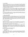
A major issue in the implementation of the simulator is that of how best to simulate a parallel
architecture on a sequential rnachine. In the time/space diagram (fi7. 8) one has a choice
between simulating the processing on all the processors for one time intervai before moving on
to the next, or of simulating the program on one processor to completion before doing the next
processor. Simulating an S-bit multiplication by doing single bit additions over the whole array
is a painfully slow process, but when processors are allowed to communicate dependencies will
occur which necessitate this (for example, a program could be bit-serially adding in the carry
output from a neighbouring PPEL).
PROCIjSSORS
+
TIME
(ie. successive
-'--'-'
bits in multi-
bit operations)
"correct"
"fast"
Fig.
8
::,)
Simulation strategies
The approach adopted here is to do the "correct" bit-serial simulation normally, but whenever
possible use a much faster higher level simulation making direct use of the arithmetic available
on the machine running the simulator. In general it is necessary to do the bit-serial simulation
when communications occur (unless their effect can be predicted) and when several ILPs are
running in sync. If the ILPs are running out of sync (in which case any off-cluster communications would lead to unpredictable results anyway), muitibit PPEL macros such as ADD are
implemented directly, with an orders of magnitude increase in speed.
A related problem is keeping track of the simulation time. As the ILP control flow can follow
conditional branches, it is necessary to keep track of time independently for each ILP and then
use the maximum over
all the ILPs as the actual execution time for
t7
a
routine.
6. Hardware Implementation
We are curently building a prototype ILP/PPEL cluster with discrete circuitry, using programmable logic and off-the-shelf micro-controllers.
We have already started work building an 8x8 transputer system, and when this is complete we
will interface some ILPI?PEL prototype cells to it. Clearly though, it is impracticai to build a full
size array of PPEL processors with discrete components, so some of the processing power of the
transputer system will be userl to provide an efficient simulation of the lower layers for algorithm development.
Eventually of course we would like to implement the architecture in VLSI and build a full size
working machine. With a concrete model of the architecture we will be able to perform a VLSI
feasibility and design study, with a view to designing first a custom VLSI PPEL chip and then an
ILP processor.
We intend to manufacture at least 16 PPELs in one package (arranged as 4x4, needing 16 adjacent neighbour data lines, plus vertical communication, conffol lines etc., and 512 bytes static
RAM), wrth32 chips and two corresponding intermediate level processors on a board. The full
256x256 pixel resolution machine would then need 128 such cards, plus 16 transputer boards.
The speed we can achieve depends on having ILPs and instruction sequencing fast enough to
keep up with the bit-serial PPELs. These are likely to have a 50-100 ns cycle time if we implement them using 3p CMOS. A full size array could then perform a 5x5 8-bit convolution in
around 5x5x8x8x100ns = 150ps.
7. Objectives
We are studying the effectiveness of this architecture for iconic to symbolic translation of data
by using the example of edge detection and line extraction, and are developing metrics for the
processor. In this respect the simulator provides a useful vehicle for focussing our ideas about
concurrency, as well as modelling the architecture.
The exercise of implementing some basic image processing algorithms on the simulator has
already pointed up some deficiences in the original design, such as the need for additional general purpose flags in the PPEL processor, especially when dealing with multi-bit calculations and
neighbour communications at the same time.
There are still details of the PPEL cell design which need to be finalised, such as whether and
how the PPELs will be individually addressable by their ILP, how images will be loaded from a
crunera, whether we want 4- or S-way connectivity at the PPEL level, and whether a more
advanced form of input from rhe neighbours (eg. wired-OR over the 8 inputs) would be useful.
To answer these questions we need to do further timing studies, and look at the implications on
some typical algorithms using the simulator.
With our transputer system we will shortly be able to start detailed work on higher level algorithms and architectural issues, such as communication bandwidth requirements between the
ILPs and the transputers.
18
8. Summary
A project of this kind involves work spanning many different fields. Because machines performing parallel processing are stiii relatively new, much of the initial effort was concerned with systems issues. Before we are able to do any detailed VLSI design work, it is important to have a
coherent programming model for the proposed system to guide us.
To this end a reasonable amount of work has gone into identifying the operators and control constructs which are useful when programming a multi-SIMD architecture of this kind (at the lower
levels of the pyramid). hogramming at the higher level is likely to be more application specific,
but the interface to the lower level will take the form of remote procedure calis.
The main theme of our work is the transition from an iconic to a more compact and meaningful
symbolic data representation. We believe a hiearchical architecture, with different types of processor to match the differing rypes of data, is very promising for image understanding applications, and we are ctrrently building a prototype machine to carry these ideas further.
9. Acknowledgements
This research was carried out by the VLSI group at Warwick, and the author would particularly
like to acknowledge the contributions of Graham Nudd and John Vaudin who did much of the
initial work, as well as thanking the other members of the goup for their numerous helpful comments. The work was supported in part by Alvey Project ARCH013 "Dedicated VLSI Arrays",
and we would like to express our gratitude to the Alvey Directorate for making these funds
available.
References and Bibliography
AMD Inc. (1982). " Am2909, Am2910, Am29l1 microprogram sequencers" , Bipolar Microprocessor l-ogic and Interface Data Book, Advanced Micro Devices, Sunnyvale, California.
Ballard, D.H. & Brown, C.M. (1982). Computer Vision, Prentice-Hall.
Batcher, K.E. (1980). "Design of a Massively Parallel Processor",IEEE Trans. on Comp., C-29,
pp.836-840.
Cantoni, V. & Levialdi, S. (eds.) (1986). Pyramidal Systems for Computer Vision (Proceedings
of NATO Workshop at Maratea, Italy, May 1986), NATO ASI Series F-25, Springer Verlag.
Duff, M.J.B. (1978). "Review of the CLIP image processing system", Proc. National Computer
Conference, pp. 1055- 1060.
Duff, M.J. & Fountain, T.J. (eds.) (1986). Cellular Logic Image Processing, Academic
Press,
New York.
Foster, C.C. (1976). Content Addressable Parallel Processors, Van Nostrand Reinhold, New
York.
Fountain, T.J. (1985). "Plans for the g-W7 chip", in Integrated Technology for Parallel Image
P r o c es s i ng, Academic Press.
Fountain, T.J. (1986). "Array architectures for iconic and symbolic image processing", rn Proc.
9th Int. Conf. on Pattern Recognitiorz, Paris, October 1986.
19
Gonzalez, R.C. & Wintz, P. (1987). Digital Image Processing, Addison-Wesley.
Granlund, G.H. (1981). "The GOP parallel image processor",in Digital Image Processing Systems (eds. Bolc and Kulpa), pp.201-227, Springer-Verlag, Berlin.
Hillis, W.D. (1985). The Connection Machine, MIT
Press, Massachusetts.
Hoare, C.A.R. (1985). Communicating Sequential Processes, Prentice-Hall International.
Howarth, R.M. & Vaudin, C.J. (1986). WHIP: The Warwick Hierarchical Image Processor,
Internal Document, Dept. of Computer Science, University of Warwick, Nov. 1986.
Hunt, D.J. (1981). "The ICL DAP and its application to image processing",inLanguages and
Architectures for Image Processing (eds. M.J.Duff & S.Levialdi), pp.275-282, Academic
Press. London.
Inmos Plc (1984). Occam Programming Manual, Prentice-Hall International.
Inmos Plc (1985). Transputer Reference Manual,Inmos Plc, Bristol.
May, D. (1986). Occam-2 Product Definition,Inmos Plc, Bristol.
Nudd, G.R. (1930). "Image-understanding architectures", Proc. National Computing Conference, pp.377 -390.
Nudd, G.R. (1934). "VLSI systems for image processing" , in VISI for Pattern Recognition and
I mag e P ro c es si ng, Springcr Verlag.
Nudd, G.R., Etchells, R.D. & Grinberg, J. (1985). "Three-dimensional WSI architecture for
image understanding" in Journal of Parallel and Distibuted Computing,l No. 3.
Page, I. (i983). "DisArray: a 16x16 rasterop processor", in Eurographics '8-3 (ed. P.J.W. ten
Hagen), pp.367 -381, Elsevier Science Publishers, Amsterdam.
"The GRID parallel computer system", in Image Processing System Architectures (eds. J.Kittler & M.J.Duffl,pp.23-35, J.Wiley & Sons.
Pass, S. (1985).
Reddaway, S.F. (1978). "DAI' - a flexible number cruncher", Proc. 1978 LASL Workshop on
Vector and Parallel Proct.ssors, Los Alamos, pp.233-234.
Reynolds, D.E. & Otto, G.P. (1981). IPC User Manual (CLIP Image Processing C), Report No.
82/4, Dept of Physics and Astronomy, University College London.
Rice, T.A. & Jamieson, L.H. (1985). "Parallel processing for computer vision", in Integrated
Technology for Parallel lrnage Processing, Academic Press.
Shu, D.B, Nash, G. & Weems, S. (1988). "Image understanding architecture and applications",
to appear in Machine Vision (ed. ???), Prentice Hall.
Uhr, L. (1972). "Layered 'recognition cone' networks that preprocess, classify and describe",
I EEE Trans.
o
n
C omputers,
21, pp.7 58-7 68.
and augmented pyramids", in Computing
Structures for Image Proccssing, pp.95- 1 12, Academic Press.
Uhr,
L. (1983). "Pyramid multicomputer structures
20