1
The University of Lethbridge
CHEMISTRY 3820 LABORATORY MANUAL
CHEMISTRY OF THE TRANSITION
ELEMENTS
Anno Domini 2000
René T. Boeré
Department of Chemistry and Biochemistry
1
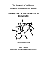
18
1.0079
4.0026
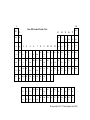
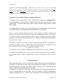
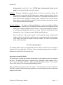
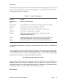
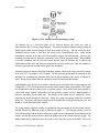
Chem 3820 Standard Periodic Table
H
1
6.941
13
14
15
16
17
9.0122
10.811
12.011
Be
B
C
14.006
7
15.999
4
18.998
4
N
O
F
Ne
26.981
5
28.085
5
7
30.973
8
8
32.066
9
35.452
7
10
39.948
Al
Si
P
Li
3
4
5
22.989
8
24.305
0
Na
Mg
11
39.098
3
12
40.078
K
19
85.467
8
Rb
Ca
20
87.62
Sr
137.32
7
Cs
Ba
Fr
87
3
44.955
9
Sc
21
88.905
9
Y
38
37
132.90
5
55
(223)
He
2
4
47.88
Ti
56
226.02
5
91.224
Zr
40
178.49
Hf
72
(261)
Ac-Lr
Ra
6
7
8
9
10
11
50.941
5
51.996
1
54.938
0
55.847
58.933
2
58.693
63.546
Ni
Cu
V
Cr
Mn
22
39
La-Lu
5
Rf
23
92.906
4
Nb
41
180.94
8
Ta
73
(262)
Db
24
95.94
Mo
25
(98)
Tc
Fe
26
101.07
Ru
42
43
44
183.85
186.20
7
190.2
W
Re
74
(263)
Sg
75
(262)
Bh
Co
27
102.90
6
Rh
(266)
As
32
106.42
107.86
8
112.41
1
114.82
118.71
0
33
121.75
7
Ag
Cd
Sn
Sb
47
196.96
7
48
200.59
50
207.19
51
208.98
0
Pd
46
78
Au
Hg
80
79
Hs
Ge
15
74.921
6
31
Pt
(265)
Ga
14
72.61
30
Ir
77
Zn
13
69.723
29
195.08
76
65.39
28
45
192.22
Os
12
6
In
49
204.38
3
Tl
Pb
82
81
Bi
S
16
78.96
Se
Cl
17
79.904
Br
2
20.179
7
Ar
18
83.80
Kr
34
35
36
127.60
126.90
5
131.29
Te
I
52
(210)
53
(210)
Po
At
84
85
173.04
174.96
7
Xe
54
(222)
Rn
86
83
Mt
104
105
106
107
108
109
110
111
140.11
5
140.90
8
144.24
(145)
150.36
151.96
5
157.25
158.92
5
88
138.90
6
Nd
Pm
La
Ce
Pr
57
227.02
8
58
232.03
8
59
231.03
6
238.02
9
237.04
8
Ac
Th
Pa
U
Np
89
90
91
60
92
61
Sm
62
(240)
Pu
94
Eu
63
(243)
Am
95
Gd
64
(247)
Cm
96
Tb
162.50
Dy
66
164.93
0
Ho
65
(247)
(251)
67
(252)
Bk
Cf
Es
97
98
99
167.26
Er
68
(257)
Fm
100
168.93
4
Tm
69
(258)
Md
101
Yb
70
(259)
No
102
Lu
71
(260)
Lr
103
93
Developed by Prof. R. T. Boeré (updated July, 2000)
Introduction
Monday
Wednesday
Friday
Lab
6/9
8/9
8/9 3hr spectroscopy
lecture
11/9
Last add/drop day 12th
13/9
15/9
18/9
20/9
15/9
Lab intro & check-in
(attendance compulsory)
22/9
LS1a
25/9
27/9
Assignment #1
22/9
29/9
Test #1
2/10
4/10
29/9
Assignment #2
6/10
LS1b
6/10
LS2a
9/10
***holiday***
16/10
11/10
Test #2
18/10
13/10
Assignment #3
20/10
13/10
LS2b
20/10
LS3a
23/10
25/11
Test #3
30/10
1/11
27/10
Assignment #4
27/10
3/11
3/11
LS3b
LS4a
6/11
8/11
Test #4
13/11
***holiday***
15/11
20/11
22/11
10/11
Assignment #5
10/11
17/11
17/11
LS4b
LS5a
Test #5
27/11
29/11
4/12
6/12 Test #6
Last day of class
Chemistry 3820 Laboratory Manual
24/11
Assignment #6
24/11
1/12
1/12 Lab cleanup &
checkout
LS5b
Page I - 1
Introduction
Table of Contents
Introduction
Page
Laboratory operation and evaluation
I–5
General laboratory procedures
I–9
Measuring IR spectra using the FTIR instrument
I–27
Chemistry Laboratory Rules and Safety precautions
I–37
Safety consent form
I–39
Glassblowing course
I–40
Expt. No.
Experiment Title
Page
Part I - Werner coordination compounds
1.
Ionization isomers: pentamminebromocobalt(III) sulfate and pentammminesulfatocobalt(III)
bromide
Introduction
1-1
Pre-lab exercise
1-2
Procedure
1-3
References
1-5
2.
Linkage isomers: nitritopentamminecobalt(III) chloride and nitropentamminecobalt(III) chloride
Introduction
2-1
Pre-lab exercise
2-2
Procedure
2-2
References
2-4
3.
Resolution of optically active complexes: tris(1,10-phenanthroline)nickel(II) perchlorate
Introduction
3-1
Pre-lab exercise
3-2
Procedure
3-2
References
3-5
Chemistry 3820 Laboratory Manual
Page I - 2
Introduction
Part II - Ligand field theory
5.
6.
Studies of ligand field strengths: some chromium complexes with ligands of different ∆0
Introduction
Pre-lab exercise
Procedure
References
5-1
5-3
5-3
5-5
Magnetochemistry: synthesis and determination of the magnetic susceptibility of some iron and
nickel complexes
Introduction
6-1
Pre-lab exercise
6-5
Procedure
6-5
References
6-8
Part III - Structure and bonding
7.
8.
Five coordination: preparation and reactions of vanadyl acetylacetonate, VO(acac)2
Introduction
Pre-lab exercise
Procedure
References
7-1
7-2
7-3
7-4
Metal-metal multiple bonds: dimolybdenum tetracetate and
hexachloro-µ-hydrido-dimolybdate
Introduction
Pre-lab exercise
Procedure
References
8-1
8-2
8-2
8-4
cesium di-µ-chloro-
9. Template consensations: preparation and reactivity of manganese(II) phthalocyanine
Introduction
Pre-lab exercise
Procedure
References
9-1
9-2
9-3
9-4
Part IV - Organometallic compounds
10.
Cyclopentadiene complexes: the preparation and
ferrocene
Introduction
Pre-lab exercise
Chemistry 3820 Laboratory Manual
electrochemical characterization of
10-1
10-2
Page I - 3
Introduction
Procedure
References
11.
12.
13.
10-2
10-5
Aromaticity in cyclopentadiene complexes: the preparation
and characterization of
acetylferrocene
Introduction
Pre-lab exercise
Procedure
References
Metal carbonyls: preparation and reactions of tetracarbonyl(2,2'-bipyridiyl)tungsten(0)
Introduction
Pre-lab exercise
Procedure
References
11-1
11-2
11-2
11-5
12-1
12-2
12-3
12-5
Olefin complexes: preparation and reaction of bis(1,5-cycloctadiene)dichloroplatinum(II)
Introduction
13-1
Pre-lab exercise
13-1
Procedure
13-2
References
13-3
Chemistry 3820 Laboratory Manual
Page I - 4
Introduction
Laboratory operation and evaluation
Assignment
(a) Students who do not have credit for 3810: Complete a total of 5 experiments as follows:
One experiment from each of Parts I, II, III and IV
The glassblowing course
(b) Students who have credit for 3810: Complete a total of 5 experiments as follows:
One experiment from each of Parts I, II, III and IV
One additional experiment from Parts I, II, III or IV
Students will work in assigned pairs, but must submit independent reports. Any evidence of
passing-on portions of reports, either between partners, or to others, will be treated as
plagiarism and prosecuted according to the rules of the University. Shared work in the pre-lab
exercises is, however, permitted (though not required). Beyond this proviso, the utmost cooperation and
collegiality in the laboratory portion of this course is encouraged.
Glassblowing
Mr. Luis Delgado will instruct two sessions in glassblowing for each student (in small groups). These
will be scheduled in laboratory periods. Each student must submit for evaluation to your instructor one
example of each of the five projects assigned. A mark will be awarded, of equal weight with one
"laboratory report and results".
Experiments
The lab is worth 30% of the total grade for Chem 3820. These 30 pts are broken down as follows
(except for glassblowing and project labs):
Pre-lab exercises
Laboratory reports and results
Laboratory notebook
Instructor's evaluation
5 pts
15 pts
5 pts
5 pts
30 pts
Each experiment carries equal value towards the total.
The pre-lab exercise must be completed in writing in the laboratory notebook at the start
of each Experiment record, AND be discussed orally with the instructor no later than the
morning before the laboratory period. A student who has not done so will be barred from
the lab during that afternoon.
The instructor's evaluation will be based on an assessment of the student's advance preparation and
understanding of the experiment, industry, laboratory technique, safety consciousness, consideration of
Chemistry 3820 Laboratory Manual
Page I - 5
Introduction
others, cleanliness and tidiness, and the quality of the results. A sample of each compound synthesized
must be available for examination by the instructor.
Laboratory Notebook
A complete accurate record is an essential part of chemical research. Although your Chemistry 3820
notebook is not a record of original research, an important objective of this laboratory is to provide
some training in keeping a research notebook. The record of any experiment should be sufficiently clear
that another chemist reading it could understand exactly what was done, what results were obtained,
and if necessary repeat the work exactly as it was done. Your notebook will be judged primarily on
how well it meets these criteria. Clarity and completeness are more important than neatness. It is not
necessary to adhere to any particular format or organization.
A bound, hard cover, lined notebook is required. Spiral or loose-leaf notebooks are unacceptable.
The pages should be numbered consecutively and some blank pages left at the beginning for a table of
contents. Begin each experiment on a new page. If you have read the entire procedure in advance you
will have some idea how much ni formation is to be recorded. Leave enough space to record the
experiment on consecutive pages. Each experiment should be dated. When the experiment extends
over more than one laboratory period, a date should be entered at the beginning of the entries for each
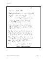
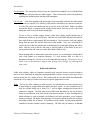
separate day's work or observations. (See Figure I-1.)
Include a short tabulation of the physical and chemical data of the compounds you are using, i.e. bp,
mp, solubility etc. (consult the CRC Handbook for this information). Important equations (e.g. those
developed for the pre-labs) should be included as well. All data are to be recorded directly into the
laboratory notebook at the time they are obtained. Do not write data on a loose piece of paper for later
copying. Nothing should ever be erased or removed from the notebook. If you make an incorrect
entry, draw a line through the mistake and add a correction.
The laboratory notebook is also a good place to write down your thoughts and speculations as to the
progress of your experiments. You may wish to include alternate methods and techniques in order to
better achieve the end result. Finally include any notes that may aid you in understanding and writing up
the experiment, e.g. structures, references, equations.
Laboratory Reports
You will be required to provide a short typed report on every experiment you perform. These reports
should not be a regurgitation of the information provided in the laboratory manual, but rather a concise
summary of the results obtained. Two or three pages will usually be sufficient.
Chemistry 3820 Laboratory Manual
Page I - 6
Introduction
Figure I-1 Sample of notebook page
Chemistry 3820 Laboratory Manual
Page I - 7
Introduction
A statement of all experimental measurements should be provided. Specify the number of moles of
reactants, reaction conditions and a simple sketch of the apparatus would be useful, as well as a
description of any variations in the procedure from that outlined in the manual. Yields of products,
melting points, spectral results and their interpretation should all be clearly and neatly laid out.
References to background information, mechanisms, spectral or structural interpretation or any physical
data, etc. should be included. The references should be listed under a separate heading at the end of
the report, in the order in which they were cited. The format for such references varies from journal to
journal; the style of Can. J. Chem. or Inorg. Chem. is recommended.
A crucial part of your write-up is your response to the points raised at the end of each experiment.
These questions are designed to probe your understanding of the chemistry involved; you may well have
to consult the literature cited in the manual in order to find an answer. One or more questions on the
final exam will probably be lifted from the material covered in the laboratory, so you are advised to
study these points carefully.
Each report will be due a week after the completion of the experiment. They must be handed in to your
instructor, who will mark them. For "security"
reasons the reports will not be returned to
you until the last week of classes. Your
grades, however, will be available one week
after submission of the reports. Your lab
note-books will be examined periodically
during the lab periods and at the end of the
semester.
Suggestions
Your instructor appreciates feed-back and
constructive criticism regarding the operation
of the laboratory and the design and
effectiveness of the experiments. Suggestions
are welcome.
Chemistry 3820 Laboratory Manual
Page I - 8
Introduction
General Laboratory Procedures
Use of Time
The efficient use of time is an asset not only to a student but especially to a researcher. Plan your
experiments so that you will profitably use time which would otherwise be spent watching, e.g. a
distillation, a sublimation or a non-hazardous reaction that need not be attended. This course allows
some latitude in the planning of experiments and you should be constantly looking for opportunities to
use the available time effectively.
Cleanliness
......is next to Godliness. Since most of the experiments will involve the use of equipment which other
students will use during the course, it is absolutely essential that all equipment be left in good condition at
the end of each period. Any equipment which is broken should be reported to the instructor
immediately so that a replacement may be found in time for the next class. Wash bottles of detergent,
alcohol and acetone are provided at each sink, as well as scrubbers, sponges and rubber gloves. If you
have difficulty cleaning a particularly dirty piece of glassware, notify the lab supervisor.
Balances and weighing
A great many experiments in chemistry involve weighing at some stage. Much time can be wasted over
weighing procedures, and one of the biggest time wasters is the habit of weighing to a degree of
accuracy in excess of the requirements of the experiment.
For synthetic work, including parts of most of the experiments in this course, weighing to 0.1 g or 0.01g
is quite sufficient. Only for analytical work, such as in the characterization of some of the compounds
prepared in this course, is greater accuracy required, on the order of 0.001 g or 0.0001g.
Even if weighing is only carried out to the required degree of accuracy, time can be wasted in the actual
process, and unless some method is used whereby weighing is carried out rapidly, many experiments
cannot be done in the time normally available.
At no time are chemicals to be weighed out onto to the pans of the ANALYTICAL BALANCES.
These include all the balances located in the balance room (D-778), some of which are
piezoelectric and some opto-mechanical. All of these balances will be irreparably damaged by
exposure to the kinds of chemicals you will be handling in this laboratory. For synthetic work,
you will use only the top-loading balances located in the lab (D-776). Please do not disturb the
Freshman classes by queuing up at the balances located in their labs. Should you require a more
accurate measurement than allowed by the top-loaders, follow the method of weighing by difference
Chemistry 3820 Laboratory Manual
Page I - 9
Introduction
described in the following paragraphs. Although they are more robust, even the top-loading
balances are susceptible to corrosion. Make it a practice to clean up any spilled chemicals on or
around the balances immediately! Balances used in these laboratories (all types) cost between
$2000 and $3000, and must be treated with respect.
Suggested accurate weighing technique: weighing by difference
To weigh an accurate amount of solid (i.e. to the nearest 0.001 g or better) place a weighing bottle on
a top-loading balance, tare it, and weigh out a rough amount of solid as close as possible to the accurate
weight required. If the solid contains large crystals or lumps it should be lightly ground in a mortar
before weighing.
The weighing bottle with contents is now capped, wiped clean and weighed using the correct procedure
on the analytical balance, the weight being recorded immediately in your notebook.
Return to the lab, and tip the solid into your flask, vessel or whatever is suitable, no attempt being
made to remove the traces of solid which will cling to the weighing bottle. Return to the balance
room, and re-weigh the nearly empty bottle accurately. The loss in weight is the accurate weight of
solid taken. This avoids the rather awkward process of washing out all the solid from the bottle and is
quicker and more accurate.
The method is often used, as it is rarely necessary to weigh out an exact amount. It is bad practice to
weigh out, for example, 1.25 g of a solid to make an exact 0.10 M solution. It is better to use the
above method, finish up with a weight of 1.32 g and express the solution as
(1.32/12.6) M = 0.105 M
This avoids the very messy practice of adding and removing odd crystals to try to get a weight exact.
By using the above method it is never necessary to have any loose chemicals near an accurate balance.
The preliminary transfer is done at a rough balance, and only a closed bottle is used on the main
balance.
Setting up apparatus
When ground-glass joints are used, it is not necessary to lubricate them except when high temperatures
are involved. If a joint becomes seized, try the following methods of loosening it (a) rock the cone in
the socket, (b) tape the joint gently with a block of wood, (c) warm the joint in a small flame, then tap
gently, (d) soak the joint in penetrating oil, then try tapping.
A common cause of seizure is a caustic alkali. Try to keep alkalis off the ground-glass, and if they do
get on it, wash thoroughly as soon as possible. Seizures can usually be avoided by dismantling the
apparatus immediately after use. Where required, the procedures call for lubricating the joints with
Chemistry 3820 Laboratory Manual
Page I - 10
Introduction
silicone grease ("high vacuum grease"). CAUTION: silicone grease may cause corneal damage.
Make sure you wash thoroughly with soap and water to remove any silicone grease from your
skin, to avoid accidental transfer of the grease to your eyes.
Care should always be taken, when glass apparatus is set up, to avoid strain. It is best to start with
one piece, and build up from there. To take the apparatus for distillation as an example
(a)
(b)
(c)
(d)
Lightly clamp the flask at a height convenient for heating,
Attach the still-head, screw-cap adapter and thermometer (no more clamps are needed for
these),
Attach the rubber tubing to the condenser, then position a clamp and stand so that the
condenser will rest on the lower, fixed, side of the clamp. Attach the condenser to the
still-head, and clamp lightly,
Attach and support the receiver adapter and the receiver.
A similar procedure should be followed for the other assemblies.
Notes on individual assemblies
Reflux Clamp the flask and the condenser. If an air condenser is used, clamp it at the top.
Distillation
(a)
Use a vented receiver adapter in the following circumstances:
if a noxious gas or vapour is given off, and must be led off by rubber tubing to an
absorption apparatus or a sink,
(b)
if an inflammable vapour is given off (for example in ether distillation), and must be led
off by rubber tubing to below bench level.
Where an air condenser is specified, it is frequently adequate to attach the receiver adapter
directly to the still-head.
Fractional distillation Clamp the fractionating column only at the top. If a column is not available, a
vertical air condenser or an ordinary condenser with an empty jacket can be used instead,
though it will be less efficient.
Gas evolution A 250 mL flask, with a B24 joint, and a 100 mL dropping funnel are satisfactory for
most purposes. If these are not available, it is convenient to prepare a number of standard
rubber stoppers, each carrying a dropping funnel and a delivery tube, which will fit 250 mL
wide-necked flasks.
Gas drying If ground-glass jointed apparatus is not available, a 250 mL conical flask with a rubber
stopper is perfectly adequate.
Chemistry 3820 Laboratory Manual
Page I - 11
Introduction
Gas absorption If it is necessary to dissolve a gas in a liquid, the best method is to use a Büchner flask
fitted with a wide glass tube in a rubber stopper. This overcomes the 'suck-back' problem by
equalizing the internal pressure with that of the atmosphere.
Use of corks Even when apparatus with ground-glass joints is normally used, there are still occasions
when corks are required. For efficiency corks must be rolled before use, and bored with care.
A cork of the correct size should only just go into the neck of the flask. Soften it by rolling
between the fingers, or between sheets of paper on the bench. Never try to roll a cork which
already has a hole in it; it will almost certainly split.
To bore a cork, or a rubber stopper, choose a sharp borer slightly smaller than the tube or
thermometer which is to go into the hole. Hold the cork in the hand, and push and rotate the
borer until the hole is approximately half way through it. Now reverse the cork, and continue
boring from the other end until the holes meet in the middle. Now use a rat-tailed file to
increase the size of the hole until the tube or thermometer fits it with gentle pushing, but with no
strain. Place the cork on the file, and rotate it with the hand or on the bench; do not use a
sawing action as this will cause an eccentric hole which is likely to leak.
When inserting tubes or thermometers into holes in corks, it is an advantage to moisten them
with a little ethanol as a temporary lubricant. If a cork becomes stuck to a tube or a
thermometer during use, it is best to cut it off, rather than risk breakage. The majority of cuts
which occur in the laboratory happen when pushing tubes through, or removing them
from, corks.
Reflux and distillation
Unlike ionic reactions, which are frequently extremely rapid, reactions between covalent substances
tend to be slow. Particularly in main-group and organometallic reactions, it may be necessary to keep a
reaction mixture hot for a matter of hours. This, coupled with the fact that volatile and inflammable
solvents have to be employed, makes it necessary for special equipment to be used.
Reflux
The use of a reflux condenser is often necessary. It is used whenever a reaction mixture has to
be kept boiling for an appreciable time and the solvent is volatile. A water condenser may be
used for solvents boiling up to about 130 C, and for higher boiling-point solvents an air
condenser is adequate. The flask must never be filled more than half way, the size of flask is
chosen by consideration of the total volume of the reaction mixture. A piece of boiling stone or
similar substance is used to promote even boiling for all reflux procedures, or else magnetic
stirring is employed. The object of the apparatus is to keep the solution hot while the reaction is
proceeding, without loss of solvent. It is pointless to boil violently, and the heating should be
controlled so that the solution is merely simmering. The flask may be heated by an electric
Chemistry 3820 Laboratory Manual
Page I - 12
Introduction
heating mantle controlled by a Variac (NEVER plug a heating mantle directly into the
mains!), or by using an oil bath on an electric hot plate.
Distillation The purpose of distillation is to purify a liquid, or to remove a solvent from a solution. The
flask must never be more than half full, boiling stone or magnetic stirring must always be used,
and the choice of condenser is the same as for reflux work. The heating of the flask may be by
any of the usual means. Distillation of a liquid to purify it should be at such a rate that no more
than 2 drops per second of distillate are obtained. On the other hand, removing a large quantity
of solvent may be done much more rapidly.
Fractional distillation
The purpose of fractional distillation is to separate two liquids of different
boiling-point. As with other forms of distillation, the flask must never be more than half full, and
boiling stone or magnetic stirring must always be used. To get a good separation of the liquids,
it is essential that the distillation be carried out very slowly. The slower the distillation the better
the separation. A rate of 1 drop per second of distillate should be the aim.
Since the efficiency of the process depends on the fractionating column reaching thermal
equilibrium (that is, there should be a gradual increase in temperature from the top to the bottom
of the column), best results are obtained if drafts are excluded. The source of heat should be
steady, and not intermittent.
Use of the separating funnel
The separating funnel is used for several important processes. Unless care is taken, its use can be one of
the major causes of mechanical loss. The choice of size is particularly important and, as with flasks in
distillation, the smallest which will do the job is best.
Separating two immiscible liquids
The liquid mixture is poured into the funnel, and the funnel is gently agitated to assist in the separation
into layers. The funnel should always be stoppered, but if a particularly volatile substance, such as
ether, is present, the funnel should be vented occasionally through the stopcock (hold it slightly
inverted while doing this) to avoid the possible buildup of pressure.
When separation into layers has occurred, the stopper is removed and the lower layer run off into a
small flask. Swirling the funnel and allowing separation to occur again frequently provides a further small
sample of the lower layer.
Chemistry 3820 Laboratory Manual
Page I - 13
Introduction
The top layer is poured from the top of the funnel into a second flask. It is a wise precaution always to
keep both liquids, even if one of them is to be discarded. It is surprising how often the wrong layer is
thrown away!
Washing a crude liquid
One of the commonest procedures consists in shaking up a crude liquid product with an aqueous
solution to remove some of the impurities present. The reagents should always be used in small
quantities, and the process repeated if necessary. Mechanical loss is always greater when large volumes
of washing solutions are used.
Gases are often formed in considerable quantities during the cleaning process, and it is essential to
release the pressure frequently. This is best done by inverting the well-stoppered funnel and opening the
tap.
If the required substance is the top layer, then running off the bottom layer is quite simple. The whole of
the bottom layer of waste should not be run off each time. It is better to leave a little of the aqueous
solution, and add further fresh reagent. The careful separation is only done when running off the last of
the various washing solutions. This avoids the risk of inadvertently letting out of a few drops of the
product being treated.
When the required substance happens to be the bottom layer, avoiding mechanical loss becomes more
difficult. If the product is run off between each wash and then returned to the funnel for the next, the
loss becomes very great. The best compromise is obtained by using rather larger volumes of washing
solutions, and decanting the spent solution from the top of the funnel. In this way the product never
leaves the funnel until the final wash is over. It is then run out into its receiver, leaving the final washing
solution in the funnel.
Liquid extractions
The separating funnel is often used to extract a solute from one solvent by means of a second solvent
immiscible with the first. The removal of a solute from water by means of ether is one of the commonest
applications.
The size of the funnel is chosen to accommodate the whole of the aqueous solution if possible. This
saves a lot of time which would be spent in repetition. A series of extractions with a small quantity of
ether is more effective than one with a large amount of ether. In practice the volume used is that which
gives the smallest manageable top layer, bearing in mind that the ether solution must be decanted from
the top of the funnel. If the layer is too small, decantation becomes difficult. The solution is usually
extracted about three times with fresh quantities of ether, and all the ether extracts are decanted into one
flask. After the final extraction the aqueous layer is run off, and the last ether layer decanted completely
into the flask. The ether solution is then dried, and the ether removed by distillation to obtain the solute.
Chemistry 3820 Laboratory Manual
Page I - 14
Introduction
Filtration methods
There are a variety of techniques used for the separation of a liquid or solution from a solid.
Simple filtration
The use of a filter funnel and a piece of filter paper folded into four is usually reserved for ionic
substances precipitated from aqueous solution. Precipitates obtained in qualitative analysis and
inorganic problem work are often rather fine, and cannot be efficiently filtered at the pump. But
covalent solids are usually to be separated from a volatile solvent, and the comparative slowness of
simple filtration brings in complications caused by evaporation.
It is essential in simple filtration to ensure that the paper is really carefully folded. The paper must be
fitted carefully into the funnel and wetted thoroughly with water, or the appropriate solvent, before
filtration is started.
The contents of the filter paper should not reach within half an inch of the top of the paper. These
simple precautions can make all the difference to the time taken for a filtration to reach completion, and
should never be neglected.
Filtering of organic liquids
This is usually done to remove solid impurities which are not in a very fine state of subdivision. A
normally folded filter paper will do for this, but the 'fluted' filter paper gives a faster rate of filtration.
Basically a fluted filter paper is one that is folded to give a corrugated effect which allows the whole of
the paper to be active rather than half as is the case with simple filtration.
There are a variety of ways of folding such a paper; one of the easiest is as follows.
The paper is carefully folded in half, opened out, and then folded in the same direction at right
angles to the original fold. The paper is then folded twice more, the folds being all in the same
direction and mutually at 45°. Each section is now individually folded in the opposite direction.
The result is a fluted paper with sixteen faces. This is placed in a suitable sized funnel, and
pushed down so that the ridges all touch the side of the funnel. Since all the paper is being used,
only one layer thick, filtration is appreciably faster.
For filtering a small amount of liquid to free it from a drying agent it is better to use a very small piece of
cotton-wool, pushed lightly into the top of the funnel stem, or even into the narrow part of a disposable
pipette. The mechanical loss entailed by absorption on a filter paper is thus obviated, and much higher
yields of product obtained.
Chemistry 3820 Laboratory Manual
Page I - 15
Introduction
The Büchner funnel and filter pump
This system of filtration is the most widely used when dealing with recrystallized substances. The
Büchner funnel may be attached to the flask by means of a cork, but a much more useful device consists
of a flat piece of rubber with a hole in the center capable of receiving the funnel stem and making a good
seal.
The disc of rubber allows, within reason, any size funnel to be fitted to any size flask. If this method is
adopted, then the size of the funnel chosen is the smallest that will hold the solid, and the flask is similarly
chosen to be the smallest that will hold the liquid, if both solid and liquid are required. If the solid is to
be discarded, than a large funnel can be used to increase the rate of filtration. If the liquid is to be
discarded, then the flask may be large enough to take all the liquid as well as the washings.
This choice of size is important, as mechanical loss can be very great during filtration.
The filter-paper disc is placed in the funnel, and wetted with the solvent present in the solution to be
filtered. It is essential that the funnel and flask be perfectly dry. If the solvent concerned is ethanol, then
the paper may be wetted with water. The pump is turned on and the paper pressed into place. During
filtration the pump must never be turned off, as this may cause water from the pump to be drawn back
into the filtrate. When all the material has been filtered, the pump is disconnected from the flask while
the pump is still running. If some of the solid has not been transferred to the funnel, a portion of filtrate is
retrieved and used for swilling the residue into the funnel. The solid is washed free of filtrate by pouring
a small portion of chilled fresh solvent into the funnel while the pump is disconnected. Finally, the solid
is drained as dry as possible by suction from the pump and pressure from a clean glass stopper.
Gravimetric filtration
In quantitative work it is essential that all the solid be transferred, and retained in the filter funnel. A
filtering crucible with a porous sintered-glass bottom is the most convenient apparatus to use.
Porosities from 0 (coarse) to 5 (very fine) are available, although for most purposes porosity 3 is best; a
few fine precipitates will require porosity 4.
The sintered-glass crucible is dried in an oven, cooled, and accurately weighed before use.
To collect the solid the pre-weighed crucible is set in the mouth of the Büchner flask by means of a firm
rubber cone. The pump is turned on, and as much supernatant liquid as possible is decanted off through
the crucible. The liquid should be directed into the crucible down a glass rod.
The solid is then transferred, using a gentle jet of water to swill out all particles. If solid clings to the
apparatus, it can be rubbed off using a glass rod protected with a rubber 'policeman'. The pump
Chemistry 3820 Laboratory Manual
Page I - 16
Introduction
suction at this stage should be as gentle as possible, otherwise the porous glass may clog. Finally, the
solid and crucible are washed repeatedly to remove all soluble materials, and dried to constant weight.
Drying methods
The drying of liquids
In the majority of cases with organic liquids extreme drying is not usually necessary, and drying agents
like anhydrous calcium chloride or anhydrous sodium sulfate are adequate. Of the two, calcium
chloride is the more efficient, but also the more messy.
As calcium chloride will remove water and ethanol, it is employed when both need removing but, if the
drying is only to remove water, anhydrous sodium sulfate is generally employed. Sodium sulfate will
only work at temperatures below 30°C and should be used at room temperature. It is capable of
removing its own weight of water, and the use of too much drying agent should be avoided at all times.
The drying agent will be 'wetted' with the required product, and a large mechanical loss will be entailed.
In order to dry an organic liquid, whether a product or a solution containing the product, it is placed in a
suitable sized conical flask, fitted with a good stopper or cork, and the drying agent added. The corked
flask is shaken at intervals, and left for at least five minutes, preferably longer.
If sufficient drying agent has been used some should remain unchanged in appearance: i.e. an opaque
powder of sodium sulfate or firm granules of calcium chloride.
The drying of solids
There are various methods of drying solid materials. When deciding which method to use it is important
to know something of the physical properties of the material. If dehydration of a hydrate or melting of
an organic solid occurs, recrystallization has to be repeated with further loss of time and material.
Although the method of air drying takes longer than the others, it is one of the safest for non
deliquescent solids. The damp solid, drained as dry as possible on the filter, is transferred to a
watch-glass and spread out evenly. This can be left to dry overnight in some dust-free place. If
possible a second, larger watch-glass should be arranged over the product as a precaution against dust,
but this cover should allow free evaporation.
Though the desiccator is ideal for many solids, care must be taken when drying hydrates. It is quite
possible to lose some water of crystallization if the dehydrating agent is very effective.
Samples to be dried should be spread out on a watch-glass and labeled with their name and date.
Chemistry 3820 Laboratory Manual
Page I - 17
Introduction
The desiccator must be regularly recharged with fresh desiccant, and the ground-glass seal kept greased
with the minimum of silicone grease, so it appears transparent. A few desiccants are listed in Table I-1
with comments on their relative usefulness.
Table I-1 Common drying agents
Desiccant
Remarks
Phosphorus (V)
oxide
Expensive, fast and efficient
Concentrated
sulfuric acid
Cheap, hazardous, fast and efficient. If BaSO4 is dissolved in the acid,
it precipitates when the drying capacity is exhausted.
CaCl2
Cheap, moderate effectiveness. Use if ethanol was the solvent
Soda-lime
Use if acidic vapours need to be absorbed.
Silica gel
Readily regenerated, limited effectiveness. Changes colour when
exhausted if stained with CoCl2
Drierite
(Anhydrous sodium sulfate) Commonly stained with CoCl2; Blue when
fresh, red when exhausted. Very inert; use for most applications.
Ensure it is anhydrous! Used to dry organic liquids, especially ethers.
MgSO4
It is important to remember that after opening a desiccator takes at least two hours to re-establish a dry
atmosphere.
A vacuum desiccator is used to speed the drying of a sample. The sample must be covered with a
second watch-glass and the desiccator evacuated and filled slowly to avoid blowing the sample about.
A vacuum desiccator must be covered with strong adhesive tape, or be enclosed in a special cage,
when being evacuated and de-evacuated to guard against an implosion.
Recrystallization and purification of solids
Inorganic solids, when first prepared, are rarely pure. The original solid must be recrystallized from an
appropriate solvent. If the solvent is a flammable liquid, as it often is, it is better to carry out a
recrystallization under reflux, until experience has been gained. With ethanol, a very common solvent, it
is quicker and neater to use a conical flask, but this does entail a risk of fire.
Reflux method
Chemistry 3820 Laboratory Manual
Page I - 18
Introduction
The solid is placed in a suitable sized flask, preferably a conical flask as it can be easily put aside to
cook, and a condenser attached. A little solvent is poured down the condenser and the mixture raised
to boiling point. If all the solid has not dissolved, a little more solvent is added after removing from the
hot plate, until the solid just dissolves at the boiling-point. If there are no insoluble solid impurities, the
solution will be clear. It is removed from the hot plate, and slowly cooled to room temperature. Gentle
swirling of the flask may be required to initialize crystallization after the solution reaches room
temperature. The solid usually crystallizes on cooling, but, if slow to start, scratching the inside of the
flask with a glass rod frequently helps crystals to form. The flask should be cooled at least to room
temperature, or preferably rather lower by placing the flask in iced water or in a refrigerator.
The pure product is filtered off at the pump. It is essential for the filter flask and funnel to be clean and
dry, except for the solvent concerned. The mixture to be filtered is poured on to the filter paper and the
solid remaining in the flask is washed out with the filtrate. This is important. The filtrate is, of course, a
saturated solution of the required solid, and so the filtrate cannot reduce the yield by dissolving some of
the crystals. The filtrate is used for washing out the flask several times until all the solid has been
transferred to the filter. On no account should fresh solvent be used for transferring the solid to the
filter.
The recrystallized solid is then dried in a suitable manner, bottled and labeled.
Open flask method
This is essentially the same as the previous method, but is carried out directly on the hot plate with an
open conical flask. The solvent is only just allowed to come to the boil and then the flask is removed. It
is possible to see the vapour condensing inside the flask, and there should not be a risk of fire if care is
taken. The obvious advantage of this method is its speed. The method is not suitable for low-boiling
solvents such as ether.
Recrystallization requiring hot filtration
If, during a recrystallization, there is an insoluble solid impurity, it becomes necessary to filter the hot
solution. Care must be taken that no crystallization occurs during the process as this would block up the
filter funnel and cause great difficulty. To avoid this, the following procedure is used.
The crude solid is dissolved in the solvent in the normal way, and when all the solute has just
dissolved at the boiling-point, a further small quantity of solvent is added. This ensures that
the solution is not saturated. This solution is kept hot while a separate sample of solvent is
Chemistry 3820 Laboratory Manual
Page I - 19
Introduction
heated to boiling and then poured through the prepared Büchner funnel. This procedure
heats up the funnel and flask. The filter paper, which must be in position, is held in place by
a glass rod. The funnel chosen should be reasonably large. Not only does this retain the
heat better, but filtration will be faster.
The hot solution is now filtered rapidly with the pump full on. As soon as all the solution is
through the funnel, the pump is disconnected and the funnel removed.
At this stage the solute will almost always have begun to crystallize out in the Büchner flask.
To save mechanical loss, the solution should be kept in the Büchner flask and cooled in the
normal way. The final filtration to collect the crystals therefore requires another Büchner
flask.
The use of activated charcoal
Sometimes there are coloured impurities present in the crude material to be recrystallized. These are
removed from the solution while hot by adsorption on activated charcoal.
The recrystallization is carried out normally until the crude material is dissolved. A little extra solvent is
added, and the mixture cooled slightly. A small amount of activated charcoal is added to the cooled
material. It is important to cool the solution before adding the charcoal, as this material tends to
promote boiling. Often the whole solution will boil over violently on the addition of charcoal if
insufficiently cooled.
The mixture with the charcoal is allowed to boil gently for a few minutes, and is then filtered hot, using
the method described above. It is important to ensure that the paper is well fitted or charcoal may get
round the edges and spoil the product. As in hot filtration, the funnel should be large so that the filtration
is as rapid as possible. The flask should be of a suitable size for the volume of purified solution
obtained.
Column chromatography
Chromatography using columns of adsorbent material is useful for separations on the preparative scale,
because gram quantities of material are readily purified. Many adsorbents are available, but these
experiments all use aluminum oxide or silica gel.
Packing the column
Clamp the glass tube upright and, checking that the tap is closed, half fill with the solvent required for the
experiment. Push a pad of non-adsorbent cotton-wool or glass-wool to the bottom of the tube; do not
ram it down hard.
Chemistry 3820 Laboratory Manual
Page I - 20
Introduction
Now slowly pour in roughly 25 g of chromatographic aluminum oxide or fine silica gel. Use a filter
funnel to guide in the powder and, if a blockage occurs (e.g. just above the solvent level), rock the tube
gently. Also tap the tube gently with your fingers to settle the powder uniformly and release any trapped
air bubbles.
Push a second pad of cotton-wool down the tube to protect the upper surface of the column from
disturbance. Drain off the excess solvent until the level falls to the upper cotton-wool pad; never let the
solvent level fall lower, otherwise the uniformity of the column will be ruined by trapped air bubbles.
The column is now ready for use.
Loading the column
Place a sample on the column using a pipette; a precise volume is not required, but the use of a pipette
ensures that the sample is placed directly on top of the column and does not drain down the tube walls.
Allow the column to drain slowly and wash in the sample by adding small portions of fresh solvent. The
sample should now be adsorbed as a narrow band at the top of the column.
Developing the column
Develop the column by running solvent through. Fill up the tube with solvent, then allow solvent to pass
through at the rate of about 5 mL per minute. Keep the tube topped up, as the liquid pressure will
encourage a good flow rate and there will be less danger of letting the column run dry. If the flow rate is
too slow, pressure can be applied by attaching a small hand bellows to the top of the tube.
Collect equivolume fractions of solvent draining from the column. Coloured materials are readily seen as
they are eluted from the column, but colourless substances must be found by evaporating the fractions to
dryness, or by running t.l.c. on each fraction.
Thin-layer chromatography
In thin-layer chromatography (t.l.c.) a suitable adsorbent is spread on a glass plate. After activation of
the adsorbent by heat, the plate is spotted with a dilute solution of the material under study and then
developed with a suitable solvent. When the solvent has risen a convenient distance up the thin film, the
plate is dried and treated with a detecting agent. Commercial plates with plastic or foil backing are also
available, and are extremely convenient for occasional use.
Silica gel is the preferred adsorbent for t.l.c., although cellulose and alumina thin films are readily
prepared. In all cases the adsorbent must have been specially manufactured for t.l.c. work, and it is
simpler to use materials free of special additives or binders. T.l.c. is faster than the other techniques in
Chemistry 3820 Laboratory Manual
Page I - 21
Introduction
general and sharper separations are possible, but to master the method you will have to work with care
and ensure your apparatus is properly cleaned.
Preparing the plates
(a)
A slurry of roughly 30% w/v of silica gel in chloroform is kept in a well-sealed wide-mouthed
bottle, and microscope slides are coated by dipping them into the slurry.
The slurry bottle should be placed on a large sheet of blotting paper in a fume cupboard.
Shake the slurry bottle and then dip in two well-cleaned microscope slides, held together at the
top by crucible tongs. Dip in and lift out the slides in a continuous movement; do not coat the
top 1 cm of the slides. Allow to drain briefly. Handling the edges only, ease the slides apart
and lay them, thin film uppermost, on the blotting paper for five minutes to dry.
Activation is not necessary.
If the film is not uniform, the microscope slide was not clean.
(b)
Prepare a slurry of 1 g of cellulose in 5 mL of acetone by mixing well in a small glass mortar.
Hold a 15 cm x 5 cm glass plate over a sheet of blotting paper and pour the slurry on to one
end of the plate. By gently rocking the place, spread the think film uniformly over the plate, then
lay it down for five minutes to dry.
Activation is not necessary.
By use of the same technique it is possible to spread on 15 cm x 5 cm plates slurries of alumina
or silica gel (1 g in 2.5 mL of 85% aqueous ethanol; if the slurry proves too thick or too thin,
vary slightly the volume of solvent).
Allow to dry at room temperature, then activate in an oven at about 120°C for thirty minutes.
Spotting the plates
Thin films must be handled and spotted with extra care because of their fragile nature. Spot the plates
with not more than 0.002 mL of 0.1-0.01 M solutions from a capillary or fine wire loop. If possible,
solutions should be prepared in the same solvent that will be used for development of the
chromatogram.
As many as three separate spots can be placed on a microscope slide, if channels are scratched in the
thick film with the edge of a spatula and surplus material is cleaned from the edges of the slide.
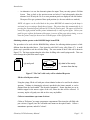
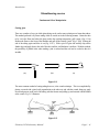
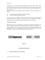
Compressed Gas Cylinders
Several experiments make use of gases which are commercially available in compressed gas cylinders.
They come in a variety of sizes with several valves and regulators. The metallic content of the values
Chemistry 3820 Laboratory Manual
Page I - 22
Introduction
may be dictated by corrosive properties of the gas. The facile reaction of N2O4 with copper, for
example, requires that the cylinder and valve contain very little copper. Many cylinders contain a safety
valve or nut which is designed to rupture if the pressure inside the cylinder exceeds the specifications of
the cylinder. Under no circumstances should anyone tamper with the safety nut.
Cylinder pressure
Diaphragm control
Needle valve
Main valve
Delivery pressure
Main valve
Two-stage regulator
Hose nipple
Needle valve
Hose nipple
(a) Gas requiring only a
needle valve
(b) Gas requiring a two-stage
diaphragm regulator
Figure I-2 Detail of the two main types of compressed gas cylinders used in the lab
The main valve (Figure I-2) on a cylinder is simply an on-off valve which allows no control of the gas
flow; it should always be used with some type of control valve. A needle valve permits such control but
if the cylinder contains a compressed gas, the cylinder pressure will decrease as the cylinder is used and
the gas flow will likewise decrease. Thus for compounds which exist as gases (e.g. CO, N2, BF3) in a
cylinder, a given flow rate cannot be maintained without continuous adjustment. Compounds which
condense to form liquids under pressure exert their natural vapour pressure so long as any liquid remains
in the cylinder. For these gases (e.g. MeBr, NH3) a continuous flow rate can be obtained with a needle
valve.
To achieve a constant flow rate for gases which do not condense under the pressure in the cylinder, a
pressure regulator is required. (Figure I-2b) First open the main valve; the gas pressure in the cylinder
is given on the right hand gauge. Then open the regulator valve by turning the lever clockwise. Finally
adjust the flow rate to the desired level by opening the needle valve. The pressure between the needle
valve and the regulator is given on the left-hand gauge. The regulator will maintain the pressure. During
the experiment, the flow can be halted by closing the needle valve, but when you are finished with the
cylinder for the day, close the main valve to prevent loss of the gas in case the regulator leaks slightly.
Do not empty a cylinder completely; leave approximately 25 psi so that the cylinder does not become
contaminated with air or other gases before it is returned to the supplier for refilling.
Chemistry 3820 Laboratory Manual
Page I - 23
Introduction
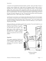
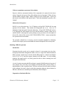
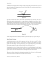
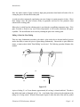
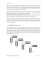
In several experiments, N2 gas will be used to flush air from a reaction system, as shown below. Before
the reaction is begun, the N2 flow is turned off with the stop-cock. This normally produces a pressure
build-up which could result in the rupture of the tygon tubing connecting the apparatus to the nitrogen
cylinder. To prevent this, it is convenient to connect an oil or mercury bubbler to the nitrogen line to act
as a pressure release valve for the excess nitrogen (Figure I-3).
Mineral oil or
mercury bubbler
Reaction flask
Figure I-3 In-line connection of a gas-bubbler
Handling Air-Sens itive Reagents
A large variety of air-sensitive reagents is now available commercially. Specific examples include
solutions of boron complexes, organoboranes, borohydrides, Grignard reagents, organoaluminums,
organolithiums, and organozincs. Since all of these reagents react with water or oxygen or both, they
must never be exposed to the atmosphere.
Most modern synthetic chemists are familiar with the utility of these versatile organometallic reagents.
However, because the compounds are air-sensitive or pyrophoric, some workers hesitate to make use
of the remarkable chemistry of these reagents. Some chemists still believe that very specialized
equipment and complicated techniques are required for handling of these materials. This is often not the
case.
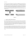
Air-sensitive reagents available from Aldrich Chemicals are packaged in special bottles. The Aldrich
Sure/Seal packaging system (Figure I-4) provides a convenient method for storing and dispensing
research quantities of air-sensitive reagents. With this bottle, reactive materials can be handled and
stored without exposure to atmospheric moisture or oxygen. The reagent comes into contact only with
glass and Teflon, yet it can be readily transferred using standard syringe techniques.
Chemistry 3820 Laboratory Manual
Page I - 24
Introduction
Figure I-4 The Aldrich Sure/Seal packaging system
The Bakelite cap on a Sure/Seal bottle can be removed because the crown cap, with its
teflon-elastomer liner, is already crimped in place. The reagent can then be dispensed using a syringe or
double-tipped needle inserted through the hole in the metal crown cap. After the needle has been
withdrawn from the bottle, a small hole will remain in the Teflon/elastomer liner. Under normal
circumstances, the hole in the liner will self-seal and the reagent will not deteriorate. However, the
possibility exists that once an elastomer is punctured, it may leak on long-term storage. This possibility
is virtually eliminated with the Sure/Seal system because when the Bakelite cap is replaced, the
Teflon/elastomer liner in the cap forms a seal against the top of the metal crown. Thus, the contents are
effectively protected from moisture and oxygen in the atmosphere.
Laboratory glassware contains a thin film of adsorbed moisture which can be easily removed by heating
in an oven (125°C/overnight or 140°C/4 hours). The hot glassware should ideally be cooled in an inert
atmosphere by assembling the glassware while still hot and the flushing with a stream of nitrogen or
argon. Spring clips or rubber bands are required to secure all joints during the flushing.
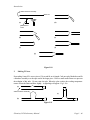
Small quantities (up to 50 mL) of air-sensitive reagents may be transferred with a syringe equipped with
a long needle (1-2 ft.). The long needles are used to avoid having to tip the reagent bottles. The reagent
may be introduced into the reaction vessel via a rubber septum. These rubber septa slowly degrade in
contact with organic vapours, and therefore will only provide a positive seal for a limited number of
punctures, depending on the needle size. The lifetime of the septum may be extended by always
reinserting the needle through the same hole. Ideally the syringe and plunger should be oven-dried
before use. The syringe and plunger should not be assembled before being placed into the oven, and
should be cooled afterwards before assembly.
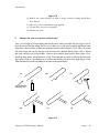
The syringe transfer of liquids is readily accomplished by first pressurizing the Sure/Seal bottle with dry
nitrogen, followed by filling the syringe as illustrated in Figure I-5. The nitrogen pressure is used to
slowly fill the syringe with the desired volume plus a slight excess (to compensate for gas bubbles) of the
reagent. Note that the nitrogen pressure pushes the plunger back as the reagent enters the syringe. The
plunger should not be pulled back since this tends to cause leaks and creates gas bubbles. The excess
Chemistry 3820 Laboratory Manual
Page I - 25
Introduction
reagent along with any gas bubbles is forced back into the reagent bottle as shown above. The
accurately measured volume of reagent in the syringe is quickly transferred to the reaction vessel by
puncturing the rubber septum on the reaction flask or additional funnel, as shown below.
Figure I-5 Filling syringe using nitrogen pressure
When handling air-sensitive materials, it is important that the user be thoroughly familiar with the basic
chemistry of the reagent. Also, the user should be prepared for unexpected problems. For example, at
least one set of clean, dry syringes and needles should always be available in case the first set becomes
plugged.
Chemistry 3820 Laboratory Manual
Page I - 26
Introduction
Measuring IR spectra using the FTIR instrument
Several of the experiments in this course require you to take an infrared spectrum of your product.
These spectra record the absorbency of light by the compound in the region 4,000 to 200 cm- 1
(wavelength 2500 to 50,000 nm.) Energies here are in the region 10-50 kJ mol- 1, corresponding to
molecular vibrations. Only compounds with covalent bonds will absorb IR light; purely ionic crystals do
not interact. So the optical 'windows' for use in IR spectroscopy are made of ionic sodium chloride, or
in some special cases, CsI.
Sample preparation
Many of the spectra you will record are of solids. In some cases, IR spectra can be recorded in
solution using expensive solution cells. Solids are prepared either as mulls (that is, a thin layer of a
paste made of the solid powder dispersed with nujol or Fluorolube oil), or as KBr pellets. Nujol is a
high M.W. alkane mixture, which reduces light scattering by the powder. As a saturated hydrocarbon,
it has absorptions at 2820-2960 cm- 1 (C-H stretch), 1460 cm- 1 (CH2 bend) and 1380 cm- 1 (CH3
bend). Fluorolube is a fluorinated hydrocarbon, and the C-F stretch occurs below 1400 cm- 1. Various
deformation bands also occur in this region. The usefulness of fluorolube is in obtaining an undistorted
view of the 4000-1400 cm- 1 region. Note that mulls are not solutions!
To prepare the mull, grind a small quantity of the substance to a very fine powder, add one drop of
nujol and mix to a paste. Don't use too much liquid, or you'll only see the nujol peaks! Spread a thin
layer on an NaCl plate and make a 'sandwich' with a second plate. Don't have the layer too thick; if it's
opaque to you, it will be opaque to the spectrometer! Insert the plate assembly into the circular sample
holder, and gently screw on the top. For instructions on data collection see the next section. Follow
exactly the same procedure with Fluorolube.
After use, clean the IR plates and the pestle and mortar using only the CH2Cl2 provided. (Chlorinated
solvents must be used in the FUME-HOOD.) Nujol does not dissolve in water, but NaCl and
especially CsI plates do, so water is NOT the solvent of choice here! Even acetone is generally too wet
to use on highly polished IR plates.
KBr pressed pellets are prepared by first grinding a small quantity of IR-grade KBr powder
(hygroscopic - stored in a desiccator! return it there!!) to a very fine powder. Then add about 5% of
this quantity of solid to be analyzed and continue grinding till an intimate mixture of uniform fineness is
achieved. Load the pellet press with the mixture, and apply the appropriate amount of pressure (see
instructions with the hydraulic press). Carefully remove the pressed pellet with plastic tweezers and
mount in the IR pellet holder for recording the data.
Chemistry 3820 Laboratory Manual
Page I - 27
Introduction
For solutions, use the 0.2 mm NaCl solution cell. Carefully fill with a concentrated solution of the
compound in the indicated solvent. This strategy ensures that the compound peaks will not be
swamped by the solvent absorptions. Note that a reference spectrum must first be recorded using the
same cell containing only the pure solvent. Make sure that the cell is completely filled, with no air
bubbles. Do not let solution spill over the sides, where it will evaporate and coat the optical
surface with solute.
Collecting Data
The BOMEM EASY software package is a simple, powerful and genuinely easy-to-use program for
the collection, display and plotting of FTIR data. You will use this program exclusively in the Chem
3820 lab. Normally the instrument will have been turned on ahead of time by the instructor.
It is very important that the BOMEM FTIR be warmed up for a minimum of ONE HOUR
before the sample compartment is opened. This is to prevent moisture collecting on the
sensitive CsI windows which isolate the sample compartment from the sensitive optical
components.
If the computer is not already on, switch it on at the main power-bar switch. When the C> prompt is
displayed on the screen, type in the word: bomem. Then press "Enter" to start the program. From here
on in, the experiment is entirely menu-driven. These menus are largely self-explanatory. For further
details not discussed here, see the photocopied excerpts from the user's manual provided with the
instrument.
The program now displays the Main Menu (Figure I-6a).
It is important to check that the computer has the correct directory activated. This is shown in the top
right hand box, just below today's date. It should read:
c:/ftirdata/c3820
If a different subdirectory is displayed, hit function key F7 on the main menu to display the File System
menu. Now hit F4 to "change directory". This will list the directories being used, and you can select the
correct one with the cursor and hit "Enter" to activate it.
Take a moment to look at the files already in your directory (Figure I-6b). For each spectrum, there
are four files. The ↓ arrow selects experiments by name. The → arrow moves into the associated right
hand set, where the ↓ arrow again selects the appropriate item. A "normal" IR spectrum will be shown
if the name and .TRANSMITTANCE extension are highlighted in green. Hitting "Enter" will display this
experiment on the computer screen (Figure I-6c). Thus
Chemistry 3820 Laboratory Manual
Page I - 28
Introduction
Chemistry 3820 Laboratory Manual
Page I - 29
Introduction
Figure I-6 Screen images of the BOMEM EASY computer program
Chemistry 3820 Laboratory Manual
Page I - 30
Introduction
after recording a spectrum, you can always come back to the spectrum on screen for further analysis,
without having to record it again. Note that data is automatically saved to disk when a spectrum is
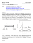
recorded. If the .RAW extension is highlighted, an odd-looking spectrum is displayed (Figure I-6d).
First of all, the baseline of this spectrum is approximately bell-curved. This reflects the intensity of the
light emanating from the light-source. It's maximum intensity is around 2000 cm- 1, and falls off in either
direction from this point. As for the absorptions, this spectrum is a combination of the actual peaks in
the sample (in the figure, polystyrene) and the background gases in the sample compartment of the IR
instrument (mostly CO2 and water vapour). This points out an important difference between the
BOMEM and the small Perkin Elmer instruments used in the organic labs:
The BOMEM MB102 is a single beam instrument, and a separate background
(reference) spectrum must be recorded before the sample can be measured.
Hitting "Esc" in any menu will move you back up to the previous menu. This is called a "hierarchical
menu organization." Hitting "Esc" too often will result in a prompt whether you wish to leave the
program.
With nothing in the sample compartment, hit F1 on the main menu to record the Reference spectrum.
You see the data acquisition menu (Figure I-6e). The title is already specified. In the Description field,
you can mention something about the reference, especially if it is unusual. Hitting "Enter" moves to the
other fields. Leave # of scans at ten, detector at DTGS 1mm. Sigma minimum depends on the
windows you are using. For NaCl, it is 600 cm- 1, for KBr, 450 cm- 1 and for CsI, 200 cm- 1. Leave
Sigma maximum at 4000 cm- 1.
Now hit F1 to start acquisition.
Never place anything on the spectrometer bench: not your coat, books, Coke and
ABSOLUTELY NO CHEMICALS OF ANY KIND. Don't lean on this bench, nor let
anyone else do so. Jarring the spectrometer during data collection will result in a poor
spectrum.
After collecting 10 interferograms, the computer averages the data and performs a fast Fourier
transform, which is displayed on the screen. You should see something similar to the "RAW" spectrum
(Figure I-6d). Hit "Esc" to return to main menu. Now hit F2 to record a transmittance spectrum (the
only kind we will do in this course).
The data acquisition screen will now allow you to fill in the name of the experiment in the first field
(Figure I-6f). Please start all experiment names with your own name, followed by the compound type,
e.g. if Sally Johnson is collecting data for the siloxane trimmer of Experiment 2, she might enter:
Chemistry 3820 Laboratory Manual
Page I - 31
Introduction
SJEX2#1
This will prevent confusion between the same compounds from each student. Keep the file name as
short as possible! In the description field, you can add some explanatory notes to distinguish this
sample from any others, e.g.:
Siloxane trimmer in CS2 solution - NaCl cells
Now press F1 to start acquisition.
Displaying and plotting spectrum
After ten scans and transformation, your spectrum will be displayed on a screen as in Figure I-6c. You
should learn certain commands which allow you to view specific regions of the trace, or expand a region
of interest. In particular, the following:
-
-
A vertical and horizontal cursor are displayed. These can be manipulated with the arrow
keys.
Pressing an arrow key while holding down the "Alt" key zooms the curve in the sense
indicated by direction, with the zooming action centered about the current position of the
cursor.
Pressing an arrow key while holding down the "Shift" key moves the whole spectrum in the
indicated direction.
"Home" resets cursors to middle.
"Home" + "Shift" resets horizontal zoom.
"Home" + "Alt" resets vertical zoom.
"Page Up" and "Page Down" switch between displayed spectra in multiple curve mode.
The function keys at the bottom are used for the purposes indicated.
-
-
F4-Analysis is used to mark the more intense peaks so that a numerical list of peaks vs.
intensity can be printed out. Follow directions in the resulting menu.
F7-Multiple curves is used to switch between various modes of display when more than one
spectrum is in memory at once. This can be very useful in comparing a known spectrum to an
unknown, or for looking for small differences between spectra of quite similar compounds.
F1-Hardcopy is used to obtain a printout. To use the digital plotter for output, consult your
instructor on the correct method for loading the plotter with paper. Within the "hardcopy"
menu, F1 - F4 refer to different plotting options. However, it is usually more useful to plot
from within the "analysis" menu, where F6 provides a "full-description" plot on the digital
plotter, with the highlighted peaks labeled with the peak-positions in wavenumbers.
Chemistry 3820 Laboratory Manual
Page I - 32
Introduction
-
An alternative is to use the dot-matrix printer for output. Then your only option is F6-Print
Screen. Then go back to the previous menu and select F4 and subsequently adjust the
tolerance level till only the 20 or so most prominent peaks are displayed with red markers.
Then press F4 to get a printout of these peak positions (i.e. the ones which were marked.)
NOTE: the paper can be rolled back in the printer BEFORE the numerical peak dump is
activated to save wasting a blank sheet of paper. The printer does this automatically by (i)
pressing the Function keypad, followed by (ii) the On Line keypad. The paper rolls back to
exactly the right position and the printer automatically is ready to print again. Unless your
peak list goes right to the bottom of the paper, just tear off the page after printing, so as to
leave the printer ready for the next user with the paper in the right position.
Obtaining solution spectra on the BOMEM single-beam FTIR
The procedure to be used with the BOMEM Easy software for collecting solution spectra is a little
different from that described above. First, locate the solid NaCl cavity cells (Figure I-7). A small
plastic cap is provided to seal the cell after filling. The cross-section of the 0.2 mm cell is shown in
Figure I-7b. The larger regions along the sides allow for filling with a small syringe needle. Take care
not to damage the crystal in the narrow region.
(a) cavity cell
(b) detail of the cavity
as seen from the top
Figure I-7 The NaCl solid cavity cell for solution IR spectra
Fill the cell with pure solvent
Using the syringe, fill the cell with pure solvent identical to that to be used for the solution
spectrum. Guidance in choosing the solvent is provided in the lecture material, or can be
obtained from the book entitled "The chemist's companion". Ensure that there are no air
bubbles trapped in the narrow region of the cell, where the data will be collected. If
necessary, tap the cell gently on a desk to drive away any bubbles.
Collect a transmittance spe ctrum of solvent
Collect as "Reference" an empty spectrometer compartment. Then insert the cell filled with
pure solvent (Capped!) into the cell-holder and mount on the optical bench. Collect a
transmittance spectrum, and call it "solvent".
Chemistry 3820 Laboratory Manual
Page I - 33
Introduction
Collect a transmittance spectrum of the solution
Prepare a relatively concentrated solution of the compound to be analyzed in the chosen
solvent. Empty the solvent out of the cell by shaking it out in a fume hood. Fill the cell once
with the solution, using the syringe. Shake it empty once more, and fill again. Cap the cell
and mount it in the holder on the optical bench. Collect the transmittance spectrum, call it
"solution".
Subtraction of the spectra
Hit ESC to get to the main menu. Use F5 Display to call up SOLUTION.RAW, the raw
spectrum for the solution. This includes the background due to air. Now use F2
Manipulate Graph and again F2 Spectral subtraction. Call up SOLVENT.RAW, and use
F1 to adjust the mix factor with the arrow keys until the baseline is smooth. When you are
satisfied, hit ESC, whereupon the system prompts you (in green letters) for a description of
the new file, which will be saved as SOLUTION.SUBTRACTION. Analyze and plot this
new spectrum in the usual manner.
The procedure outlined here is necessary, since the automatic algorithm for subtracting
reference from sample spectra cannot handle the intense absorptions of the solvent peaks.
Obtaining a KBr disc spectrum
Introduction
Potassium bromide powder can be pressed at about 10 tons pressure into clear discs
having high transmission throughout the 4000 to 450 cm-1 range of the infrared instrument.
Before pressing, samples may be mixed with the KBr powder at a sample concentration
level of 0.1% to 2%, and their spectra obtained in the KBr matrix. As in the mulling
technique, the sample must be very finely ground in order to reduce scattering losses and
absorption band distortions.
A word of caution concerning the KBr technique is required. Modifications in the spectra of
some samples may occur due to ion exchange with the KBr matrix, pressure effects, or
transformations to other crystalline forms. This does not detract from the general usefulness
of the technique, but must be kept in mind when comparing unknown spectra obtained as
KBr discs with known or standard spectra obtained by other techniques.
Preparation of the blank KBr disc
Chemistry 3820 Laboratory Manual
Page I - 34
Introduction
Place the body of the die on its base. (Consult Figure I-8 for the die parts referred to in this
discussion.) Insert the small, lower polished disk F into the die opening with the shiny
surface up (i.e. into the bottom of B). Firmly but gently insert B into A, and set upright on
the bench top. Using the weighing paper as a funnel, completely transfer 0.30 g (weighed on
a top-loader balance) of infrared quality KBr powder to the die opening. (Use KBr that
has been oven-dried and cooled and stored in a desiccator.)
Insert the upper polished disk D face down, followed by the plunger C (beveled edge up),
and with a light rotary motion of the plunger, level the sample. Carry the whole assembly,
as well as (i) clear plastic ring (ii) plastic forceps (iii) spring-loaded disc-holder to the small
grey press located next to the machine-shop on level 8. Connect the die to the vacuum
pump via the rubber hose provided, and evacuate the die to a pressure of 1 to 2 mm of Hg
for about 2 minutes to remove air from between the KBr particles.
A - Body of die, with vacuum nozzle
B - Inner part of die
B
C
A
C - Die plunger
D
D - Upper polished disk, face down
E
E - KBr plus sample
F
F - Lower polished disk, face up
Figure I-8
With the vacuum still connected, place the die on press. There should be two 5cm thick
round spacers on the piston head, leaving just enough space to place the die assembly
below the top platen. The needle valve at the left-hand-side of the press should be gently
pulled up towards you to close the hydraulic valve before pressing. Press for 3-4 minutes at
9 tons pressure on the middle scale of the press dial. This actually delivers a total
pressure of 30 tons on the 13mm die. Disconnect the die from the vacuum line, relieve the
pressure on the press by lowering the needle valve handle away from you, and remove the
die.
Chemistry 3820 Laboratory Manual
Page I - 35
Introduction
B - Inner part of die
G
C - Die plunger
F
B
E
D
D - Upper polished disk, face down
E - KBr finnished pellet
C
F - Lower polished disk, face up
G - Clear plastic ring
Figure I-9 Set-up for the removal of the disc
Invert the die and remove base A. Place the inverted die back in the press and center the
clear plastic ring on the die so that the lower plunger will be visible when forced from the
die, as in Figure I-9. Now, with the press, force the plunger upward until the lower ram and
disc just clear the body of the die. Remove the die from the press, and with the tweezers,
place the disc, which should be homogeneous in appearance and transparent, in the disc
holder. Insert the disc holder in the instrument and obtain the spectrum in the usual manner.
The spectrum should resemble that shown in Figure I-8.
Figure I-10 IR spectrum of a blank KBr disk
Grinding of samples and preparation of a KBr disc.
Place an estimated 10 to 15 mg of the sample in the agate mortar. Grind the sample with a
vigorous, firm, rotary motion, restricting the sample as much as possible to about ¼ to ½ of
the mortar. Scrape the ground sample from the sides of the mortar with the micro spatula
and discard all but about 1 mg. Weigh 0.30 g of dry KBr powder as before, and add 5 to
10 mg to the mortar containing the sample. Use the pestle to mix the KBr and sample with
a gentle rubbing motion. Do not grind the KBr during the mixing procedure since reduction
Chemistry 3820 Laboratory Manual
Page I - 36
Introduction
in particle size is not required and will lead to adsorption of water on the KBr. Now add
15 mg of KBr powder and mix as before. Add another amount of KBr approximately
equal to the total quantity in the mortar (i.e., add about 30 mg) and mix. Continue adding
and mixing KBr in this manner until all the KBr is in the mortar. If this procedure is
followed, a homogeneous mixture of the sample and KBr, with little H2O pickup on the
KBr, will result. Completely transfer the mixture from the mortar to the die using the
weighing paper and press the disc as described above. Remove the disc from the die,
mount it in the KBr disc holder, and obtain the spectrum.
Chemistry 3820 Laboratory Manual
Page I - 37
Introduction
Chemistry Laboratory Rules and Safety Precautions
1.
Never work alone in the laboratory.
2.
Smoking and eating are not permitted.
3.
Unauthorized experiments are prohibited.
4.
Know the location and use of the fire extinguisher, safety showers and first aid kit.
5.
It is required that you wear prescription glasses or safety glasses at all times in the laboratory
for your own protection. Contact lenses are particularly dangerous and they must not be worn in
the laboratory.
6.
Report all injuries to your instructor at once.
7.
Never taste chemicals or solutions.
8.
Use the fume hoods at the sides of the laboratory for all poisonous reactions or any reactions
which produce noxious gases.
9.
When diluting concentrated acid or base always add the concentrated acid or base to water
(never the reverse), while stirring the solution. Be very careful with sulfuric acid.
10.
Keep an orderly, clean laboratory desk. Return glassware to the lab drawer when finished using
it to keep the work area from becoming cluttered.
11.
Leave unneeded books, etc. outside of the laboratory. Never block aisles with personal effects,
or leave clothing, etc. on the benches.
12.
Waste crocks are provided for the disposal of all solid chemicals and paper, etc.
(1)
Non-chlorinated solvents
(2)
Chlorinated solvents
(3)
Sulfur chlorides
14.
Stock reagent bottles are placed on the side bench or beside the balances; leave them at that
position.
Chemistry 3820 Laboratory Manual
Page I - 38
Introduction
15.
Always read the label twice before taking any chemical from a bottle. If you are not sure if you
have the right chemical, ask!
16.
When pouring reagents, hold the bottle so the label points upwards facing the palm of the hand.
The accumulation of reagent on bottle lip may be removed by touching the bottle lip to the rim of
the receiving vessel.
17.
Avoid using an excess of reagent. If you happen to have measured out too much, see if someone
else can use the excess.
18.
Due to possible contamination of the contents of a whole stock bottle, never return unused
chemical to the stock bottle.
19.
Always check your glassware before you use it. If it is broken or cracked, exchange it for a new
one.
20.
There is one crock reserved for broken glass. All broken glassware should be placed in this
crock and no other.
21.
If corrosive chemicals or liquids come in contact with the skin or clothing, flood with copious
amounts of water for an extended period of time.
22.
Spilled chemicals should be wiped up immediately; spilled acid or base should be rinsed with
plenty of water and wiped up with a sponge and the sponge rinsed after.
23.
Inserting glass tubing or thermometers through a rubber stopper - first lubricate the tube and
stopper with glycerol or water, then holding the tube near the end to be inserted insert slowly
while rotating the tube. BE VERY CAREFUL!
24.
When you are ready to leave the laboratory, your bench area should be rinsed off with a wet
sponge and the water, gas, and air valves shut off.
25.
The chemistry store room is out of bounds to students. If you require apparatus, ask your
instructor for it.
26.
Disposable polyethylene gloves are provided; other glove materials may not protect you against
the chemicals handled in this lab
Chemistry 3820 Laboratory Manual
Page I - 39
Introduction
Consent Form
This form must be completed, signed, and submitted to the laboratory instructor before any laboratory
work is begun.
********
I have read and understood the safety rules that appear on pages I-33 and I-34 of this manual,
recognize that it is my responsibility to observe them, and agree to abide by them throughout this course.
Name (please print) ____________________________________________
Date ________________ Signature ______________________________
Chemistry 3820 Laboratory Manual
Page I - 40
Introduction
Glassblowing course
Fundamental Glass Manipulation
Cutting glass
There are a number of ways in which glass tubing can be cut but some techniques are better than others.
The method preferred is by flame cutting which is carried out in the following manner. Rotate the tube
to be cut in the flame and when the glass reaches the working temperature, pull it apart. (Fig. I-11A)
Redirect the flame to the front of the shoulder and pull off the existing "point" (Fig. I-11B). Reheat the
end of the tubing again and blow it out (Fig. I-11C). With a piece of glass rod carefully chip off the
feather edge and apply heat to the end of the tube until the wall thickness is uniform. With this method,
the possibility of pinhole leaks when making a join is reduced and the seal can be worked to that it is
invisible.
(a)
(b)
(c)
Figure I-11
The most common method of cutting tubing however, is the scratch technique. This is accomplished by
placing a scratch with a glass knife perpendicular to the tube axis, and with the scratch facing up, apply
downward pressure at the end of the tubing with the forearm and pulling up and outward with the thumb
at the scratch. Fig. I-12 illustrates.
Figure I-12
Chemistry 3820 Laboratory Manual
Page I - 41
Introduction
In addition to the foregoing method, cracking or cutting of large tubing can be made easier if a piece of
glass rod is heated to the melting point and is placed on the middle of the scratch previously made on
the tube. Fig. I-13 illustrates.
red hot blob
Figure I-13
Quite often a situation arises where a short section of glass tubing has to be removed. This can be a
difficult task using the methods described. A simple method to accomplish this is as follows. Make a
fairly long deep scratch perpendicular across the tube to be cut and with the scratch facing up, apply an
intense needle flame at the end of the scratch furthest away from you. The tube will fracture along the
scratch and the short section can then be removed with the aid of tweezers. Fig. I-14 illustrates.
cone of flame
Figure I-14
Another cutting method which is ordinarily available in a professional shop only is a glass cutting saw.
Hand Working Technique
A glassblowing operation is done with the apparatus corked up; a blow hose is useful. The effects
brought about by positive pressure in a closed system is expansion at the softened area; negative
pressure will cause collapse. By varying the pressure, a piece of glass tubing can be given an entirely
different shape simply by blowing or sucking on the blow hose while the glass is soft.
By applying heat to a piece of tubing and merely pulling on it, several things happen; the tube length is
increased and the wall thickness becomes thin. Similarly, if the tubing is heated and the ends are pushed
together, then the wall will be thickened and the overall length of the tube will be shortened.
When a piece of glass is heated to the working point, gravitational force will cause it to flow downward.
For this reason, rotation of the glass while it is being worked is necessary.
Chemistry 3820 Laboratory Manual
Page I - 42
Introduction
Since the surface tension of glass is relatively high, glass protrusions when heated will tend to flow in
causing the glass to become thick at that point.
As with most other compounds, superheating can cause changes in certain properties of glass. When
these changes occur, the glass becomes cloudy in appearance and loses its flow properties when
reheated to the working point.
When glass is cooled from the softening point, it goes through a crystallizing temperature range. If the
glass is twisted or flexed in any way at these temperatures, it will become translucent and appear
crystalline. This devitrification can be cured by reheating the glass to the working point.
Pulling A Point On Glass Tubing
There are many fundamental procedures with which a glass worker has to become familiar, but most
involve the ability to rotate two pieces of glass tubing synchronously. Because this is quite difficult to
master, a simple method called "Point Pulling" was devised. The following procedure illustrates this
method.
(a)
cut
8"
(b)
(c)
Figure I-15
A piece of tubing 12 or 13 mm diameter, approximately 60 cm long, is cleaned and dried. The tube is
then held in the hands as illustrated in Fig. I-15a. A soft bushy flame is directed to the midpoint of the
tubing as it is being rotated. When the heated glass begins to soften the ends of the tube are pushed
Chemistry 3820 Laboratory Manual
Page I - 43
Introduction
together slightly over a period of time until the softened glass area becomes thick. The tube is then
removed from the flame and the ends slowly pulled apart until the diameter at the midpoint is about 5
mm. When cool, the tubing is scratched with a knife at the narrowest point and separated into two
pieces (Fig. I-15b)
The synchronous rotation of the tubing when in the softened state is of the utmost importance for two
reasons:
(a)
(b)
To attain uniformity of temperature around the entire periphery.
To prevent twisting and/or buckling of the glass.
Now, take one of the pieces and hold it so that the right hand supports the point only and the flame is
directed just back from the shoulder of the tubing. Fig. I-15c. This operation of Point Pulling is
repeated until the point, when rotated in the fingers, is aligned with the axis of the tubing.
Constricting a Glass Tube
Illustrated in Fig. I-16 are two common types of constrictions. The method for fabricating these is as
follows: hold and rotate the tubing in the usual manner and direct a bushy flame at a segment of it. If a
constriction similar to Fig. I-12a is required, push on the tube ends to gather glass and thicken it at the
point where it is heated. If a constriction similar to Fig. I-12b is desired, as a final step, pull on the tube
ends slightly over a period of time until the desired internal diameter is achieved.
(a)
(b)
Figure I-16
Assigned glassblowing projects
1.
Joining Glass Tubing of the Same Diameter
Chemistry 3820 Laboratory Manual
Page I - 44
Introduction
Cut two pieces of 8 mm O.D. tubing to be 10 cm and 20 cm in length and cork one end of the 20 cm
piece. Hold both pieces in the fingers as illustrated in Fig. I-15a. (The tubing must be held in this
manner to allow the worker to blow into the end of the short piece and rotate the tubing simultaneously.)
As the tubing is rotated, direct a soft bushy flame to the tube ends (Figure I-17a). When the glass
begins to flow push the tubes together, then pull slightly in an attempt to thin the glass at the butt. Fig.
I-17b. The join is then reheated and expanded by blowing into the open end of the tube. Fig. I-17c.
The glass butt in reheated once again until the expanded section is reduced to the same diameter as the
tubing. Fig. I-17d.
(a)
(b)
(c)
(d)
Figure I-17
2.
Joining Glass Tubing of Different Diameters
Before tubing of different diameters can be joined, one end of the larger diameter must be modified as
follows. Connect a blowhose assembly to one end of the larger diameter tube (20mm) and rotate it
with the left hand. Direct the flame to the other end of the tube as shown. Fig. I-18a. When the glass
flows, with the aid of a pair of tweezers or glass rod, pull off the end as illustrated. Fig. I-18b. After the
test tube end is accomplished (Fig. I-18c) reheat it and blow a hole of approximately the same diameter
as the smaller tube (8mm). Fig. I-18d, I-18e.
Cork one end of the tubing to be joined, then heat both ends as illustrated. Fig. I-18e. (A greater
portion of the flame should be directed to the larger diameter tube since more heat is required to soften
it than to soften the smaller diameter tube.) When the ends begin to flow, join them and blow slightly.
Fig. I-18f. Reheat the junction, expand the thickened glass by blowing, then pull the ends slightly. Fig.
I-18g.
Chemistry 3820 Laboratory Manual
Page I - 45
Introduction
attach blowhose assembly
Glass rod
(a)
(d)
glassblower's
rolers
(b)
(e)
(c)
(f)
(g)
Figure I-18
3.
Making T Pieces
From tubing 8 mm O.D. cut two pieces 150 cm and 80 cm in length. Cork one end of both tubes and fit
a blowhose assembly over the open end of the longer piece. Direct a small needle flame to a spot near
the midpoint of this tube. Do not rotate the tube. When the glass reaches the working temperature
remove it from the flame and blow slightly. A slight bulge will appear. Fig. I-19a.
(a)
attach blowhose assembly
(c)
(b)
Figure I-19
Chemistry 3820 Laboratory Manual
Page I - 46
Introduction
Reheat the bulge until it collapses then quickly remove the tube from the flame and blow into the
assembly until the wall ruptures. Fig. I-19b. (The hole should not be larger than the diameter of the side
arm to be joined.) After removing excess glass fragmentation with a piece of glass rod, direct a flame
around the opening in an attempt to trim the uneven thin wall.
With the right hand position the short piece of glass tubing as shown in Fig. I-19c. Heat both openings,
join the tubes together, then check "T" alignment. (If a small gap in the join should result due to
improper positioning, take a piece of glass rod and heat it and the gap
simultaneously to the flow point and knit the pieces together. After the gap is closed, remove the excess
glass by reheating the area, dabbing the glass rod on the thickened part and pulling it away.)
Work the glass at the join by spot heating and blowing. This method ensures that rigidity of the "T" is
maintained. (It is important that the entire area be kept reasonably warm while the join is being worked,
as severe thermal shock could cause the "strained" glass to fracture.) Anneal the glass immediately after
the "T" piece is completed.
4.
Bending Tubing at Right Angles
Bending small diameter tubing is relatively simple providing the worker follows this procedure. Cork
one end of a piece of 8 mm O.D. tubing approximately 20 cm long and heat it in a wide bushy flame.
Rotate the tubing in the usual manner, but in addition, move it from side to side in the flame while it is
being rotated to heat a greater length along the tube. When the tubing reaches the working point, quickly
remove it from the flame (stop rotating), bend the open end up toward the mouth and blow. Check the
bend for alignment, etc. (Figure I-20).
(a)
(b)
(c)
(d)
Chemistry 3820 Laboratory Manual
Page I - 47
Introduction
(a)
(b)
(c)
(d)
5.
Figure I-20
Bend is too sharp causing it to kink; a longer section of tubing should have
been heated
More air pressure should have been applied
Too much air pressure was applied
Satisfactory bend
Putting a side-arm on a test-tube (Schlenk tube)
Take a 20 cm length of 20 mm tubing, and heat the end to make a test-tube end (see Figure I-18a-d).
Near the mid-point of the tubing, heat it in a low flame over a wide area around the attachment point.
Then make a narrow flame, and heat the attachment point to red heat (Figure I-21a). Blow out a small
hole in the larger tube equal to the size of the side-arm to be attached (8mm) (Figure I-21b). Reheat
this bulge, and blow out a large bubble. Remove the devitrified glass from the hole (Figure I-21c).
Attach the 8mm tubing, which should be at least 10cm long and be corked or sealed at the end, to the
larger tube as follows. Heat both pieces to red heat and carefully join them at one point (figure I-21d).
Then bend the tube in until it is attached at all points in the circumference.
(a)
(b)
(c)
attach blowhose
assembly here
(d)
(e)
(f)
Figure I-21
Chemistry 3820 Laboratory Manual
Page I - 48
Introduction
Use gentle blowing to enlarge the size of the attachment point, with the goal of achieving a uniform
thickness from the walls of the larger tube to the walls of the tube. The excess glass which has
accumulated in the joining process is converted into increased diameter of the hole (Figure I-21e & f).
When a reasonable join is obtained, carefully and thoroughly anneal the join in a cool flame. After
annealing and cooling, the side-arm can be cut about 2 cm from the larger tube, and the cut end is
flame-polished to remove sharp edges. Finally the open end of the larger tube is cut back to 3-4 cm
above the attachement point and also flame-polished.
Evaluation
Bring the completed projects to your instructor, who will evaluate them according to functionality and,
to a lesser extent, appearance. At least three of your projects must be judged "satisfactory" to pass the
lab course. All glassblowing projects must be submitted no more than two weeks after the end of your
assigned sessions.
Chemistry 3820 Laboratory Manual
Page I - 49