1
User Manual
PowerFlex 20-COMM-P Profibus Adapter
FRN 1.xxx
Important User Information
Read this document and the documents listed in the additional resources section about installation, configuration, and
operation of this equipment before you install, configure, operate, or maintain this product. Users are required to
familiarize themselves with installation and wiring instructions in addition to requirements of all applicable codes, laws,
and standards.
Activities including installation, adjustments, putting into service, use, assembly, disassembly, and maintenance are required
to be carried out by suitably trained personnel in accordance with applicable code of practice.
If this equipment is used in a manner not specified by the manufacturer, the protection provided by the equipment may be
impaired.
In no event will Rockwell Automation, Inc. be responsible or liable for indirect or consequential damages resulting from the
use or application of this equipment.
The examples and diagrams in this manual are included solely for illustrative purposes. Because of the many variables and
requirements associated with any particular installation, Rockwell Automation, Inc. cannot assume responsibility or
liability for actual use based on the examples and diagrams.
No patent liability is assumed by Rockwell Automation, Inc. with respect to use of information, circuits, equipment, or
software described in this manual.
Reproduction of the contents of this manual, in whole or in part, without written permission of Rockwell Automation,
Inc., is prohibited.
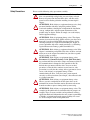
Throughout this manual, when necessary, we use notes to make you aware of safety considerations.
WARNING: Identifies information about practices or circumstances that can cause an explosion in a hazardous environment,
which may lead to personal injury or death, property damage, or economic loss.
ATTENTION: Identifies information about practices or circumstances that can lead to personal injury or death, property
damage, or economic loss. Attentions help you identify a hazard, avoid a hazard, and recognize the consequence.
IMPORTANT
Identifies information that is critical for successful application and understanding of the product.
Labels may also be on or inside the equipment to provide specific precautions.
SHOCK HAZARD: Labels may be on or inside the equipment, for example, a drive or motor, to alert people that dangerous
voltage may be present.
BURN HAZARD: Labels may be on or inside the equipment, for example, a drive or motor, to alert people that surfaces may
reach dangerous temperatures.
ARC FLASH HAZARD: Labels may be on or inside the equipment, for example, a motor control center, to alert people to
potential Arc Flash. Arc Flash will cause severe injury or death. Wear proper Personal Protective Equipment (PPE). Follow ALL
Regulatory requirements for safe work practices and for Personal Protective Equipment (PPE).
Allen-Bradley, Rockwell Software, and Rockwell Automation are trademarks of Rockwell Automation, Inc.
Trademarks not belonging to Rockwell Automation are property of their respective companies.
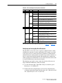
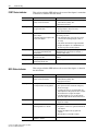
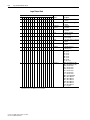
Summary of Changes
The information below summarizes the changes made to this manual since
its last release (November 2001):
Description of Changes
Page
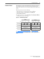
Reformatted document from half size (5.5 x 8.5 in.) to full size (8.5 x 11 in.)
Throughout
manual
Added information about Connected Components Workbench software configuration
toll for drives and connected peripherals.
Revised the ‘DPI Ports and Internal Interface Cables’ figure, and the ‘Mounting and
Grounding the Adapter’ figure to show PowerFlex 700H/S Frames 9 and larger.
2-4 and 2-5
In the ‘Applying Power’ section in Chapter 2, added new subsections ‘Start-Up Status
Indications’ and ‘Configuring and Verifying Key Drive Parameters’.
2-8 and 2-9
In Chapter 3, added new section ‘Updating the Adapter Firmware’.
3-6
In the section ‘Using Reference/Feedback’ in Chapter 5, added the following new
subsections:
• ‘PowerFlex 70/700/700H, and PowerFlex 700L Drives with 700 Control’
• ‘PowerFlex 700S and PowerFlex 700L Drives with 700S Control’
• ‘PowerFlex Digital DC Drives’
5-5
5-6
5-6
In the section ‘Using Datalinks’ in Chapter 5, added the new subsection ‘Datalink
Scaling’.
5-7
Revised Appendix C to include the following new sections:
• ‘PowerFlex 70/700/700H, and 700L (with 700 Control) Drives’
• ‘PowerFlex 700S (Phase II Control) and 700L (with 700S Control) Drives’
• ‘PowerFlex Digital DC Drives’
C-1
C-3
C-5
PowerFlex 20-COMM-P Profibus Adapter User Manual
Publication 20COMM-UM006B-EN-P
soc-ii
Summary of Changes
PowerFlex 20-COMM-P Profibus Adapter User Manual
Publication 20COMM-UM006B-EN-P
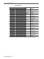
Table of Contents
Preface
About This Manual
Conventions Used in This Manual . . . . . . . . . . . . . . . . . . . . . . . . . . . . . . . . . . . . . . . . . . P-1
Rockwell Automation Support . . . . . . . . . . . . . . . . . . . . . . . . . . . . . . . . . . . . . . . . . . . . . P-2
Additional Resources . . . . . . . . . . . . . . . . . . . . . . . . . . . . . . . . . . . . . . . . . . . . . . . . . . . . P-2
Chapter 1
Getting Started
Components. . . . . . . . . . . . . . . . . . . . . . . . . . . . . . . . . . . . . . . . . . . . . . . . . . . . . . . . . . . .
Features . . . . . . . . . . . . . . . . . . . . . . . . . . . . . . . . . . . . . . . . . . . . . . . . . . . . . . . . . . . . . . .
Compatible Products . . . . . . . . . . . . . . . . . . . . . . . . . . . . . . . . . . . . . . . . . . . . . . . . . . . . .
Required Equipment . . . . . . . . . . . . . . . . . . . . . . . . . . . . . . . . . . . . . . . . . . . . . . . . . . . . .
Safety Precautions . . . . . . . . . . . . . . . . . . . . . . . . . . . . . . . . . . . . . . . . . . . . . . . . . . . . . . .
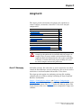
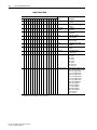
Quick Start . . . . . . . . . . . . . . . . . . . . . . . . . . . . . . . . . . . . . . . . . . . . . . . . . . . . . . . . . . . .
Chapter 2
Installing the Adapter
Preparing for an Installation . . . . . . . . . . . . . . . . . . . . . . . . . . . . . . . . . . . . . . . . . . . . . . .
Commissioning the Adapter . . . . . . . . . . . . . . . . . . . . . . . . . . . . . . . . . . . . . . . . . . . . . . .
Setting the Node Address Switches . . . . . . . . . . . . . . . . . . . . . . . . . . . . . . . . . . . . . . . . .
Connecting the Adapter to the Drive. . . . . . . . . . . . . . . . . . . . . . . . . . . . . . . . . . . . . . . . .
Connecting the Adapter to the Network . . . . . . . . . . . . . . . . . . . . . . . . . . . . . . . . . . . . . .
Node Termination . . . . . . . . . . . . . . . . . . . . . . . . . . . . . . . . . . . . . . . . . . . . . . . . . . . . . . .
Applying Power. . . . . . . . . . . . . . . . . . . . . . . . . . . . . . . . . . . . . . . . . . . . . . . . . . . . . . . . .
Chapter 3
2-1
2-1
2-2
2-3
2-6
2-7
2-8
Configuring the Adapter
Configuration Tools. . . . . . . . . . . . . . . . . . . . . . . . . . . . . . . . . . . . . . . . . . . . . . . . . . . . . .
Using the PowerFlex 7-Class HIM to Access Parameters . . . . . . . . . . . . . . . . . . . . . . . .
Setting the Node Address . . . . . . . . . . . . . . . . . . . . . . . . . . . . . . . . . . . . . . . . . . . . . . . . .
Setting the I/O Configuration . . . . . . . . . . . . . . . . . . . . . . . . . . . . . . . . . . . . . . . . . . . . . .
Setting a Fault Action . . . . . . . . . . . . . . . . . . . . . . . . . . . . . . . . . . . . . . . . . . . . . . . . . . . .
Resetting the Adapter . . . . . . . . . . . . . . . . . . . . . . . . . . . . . . . . . . . . . . . . . . . . . . . . . . . .
Viewing the Adapter Status Using Parameters . . . . . . . . . . . . . . . . . . . . . . . . . . . . . . . . .
Updating the Adapter Firmware . . . . . . . . . . . . . . . . . . . . . . . . . . . . . . . . . . . . . . . . . . . .
Chapter 4
1-1
1-2
1-2
1-3
1-5
1-6
3-1
3-2
3-3
3-3
3-4
3-5
3-6
3-6
Configuring the Profibus Scanner
Example Network . . . . . . . . . . . . . . . . . . . . . . . . . . . . . . . . . . . . . . . . . . . . . . . . . . . . . . . 4-1
SST Profibus Configuration Software Tool. . . . . . . . . . . . . . . . . . . . . . . . . . . . . . . . . . . . 4-2
Installing the 20-COMM-P GSD File Into Software Tool Library . . . . . . . . . . . . . . . . . . 4-2
Configuring the SST-PFB-SLC Profibus Scanner. . . . . . . . . . . . . . . . . . . . . . . . . . . . . . . 4-4
GSD Diagnostic Messages . . . . . . . . . . . . . . . . . . . . . . . . . . . . . . . . . . . . . . . . . . . . . . . 4-13
PowerFlex 20-COMM-P Profibus Adapter User Manual
Publication 20COMM-UM006B-EN-P
ii
Table of Contents
Chapter 5
Using the I/O
About I/O Messaging. . . . . . . . . . . . . . . . . . . . . . . . . . . . . . . . . . . . . . . . . . . . . . . . . . . . . 5-1
Understanding the I/O Image. . . . . . . . . . . . . . . . . . . . . . . . . . . . . . . . . . . . . . . . . . . . . . . 5-2
Using Logic Command/Status . . . . . . . . . . . . . . . . . . . . . . . . . . . . . . . . . . . . . . . . . . . . . . 5-4
Using Reference/Feedback . . . . . . . . . . . . . . . . . . . . . . . . . . . . . . . . . . . . . . . . . . . . . . . . 5-4
Using Datalinks . . . . . . . . . . . . . . . . . . . . . . . . . . . . . . . . . . . . . . . . . . . . . . . . . . . . . . . . . 5-6
SLC Controller Example Ladder Logic Program Information . . . . . . . . . . . . . . . . . . . . . 5-8
SLC Ladder Logic Example Main Program . . . . . . . . . . . . . . . . . . . . . . . . . . . . . . . . . . 5-12
SLC Ladder Logic Example Station 1 Program . . . . . . . . . . . . . . . . . . . . . . . . . . . . . . . 5-15
SLC Ladder Logic Example Station 2 Program . . . . . . . . . . . . . . . . . . . . . . . . . . . . . . . 5-19
Chapter 6
Using Explicit Messaging
About Explicit Messaging . . . . . . . . . . . . . . . . . . . . . . . . . . . . . . . . . . . . . . . . . . . . . . . . . 6-2
Performing Explicit Messages . . . . . . . . . . . . . . . . . . . . . . . . . . . . . . . . . . . . . . . . . . . . . . 6-2
Parameter Protocol. . . . . . . . . . . . . . . . . . . . . . . . . . . . . . . . . . . . . . . . . . . . . . . . . . . . . . . 6-3
SLC Ladder Example Station 1 Parameter Protocol . . . . . . . . . . . . . . . . . . . . . . . . . . . . 6-10
SLC Ladder Example Station 2 Parameter Protocol . . . . . . . . . . . . . . . . . . . . . . . . . . . . 6-12
Chapter 7
Troubleshooting
Understanding the Status Indicators . . . . . . . . . . . . . . . . . . . . . . . . . . . . . . . . . . . . . . . . .
PORT Status Indicator . . . . . . . . . . . . . . . . . . . . . . . . . . . . . . . . . . . . . . . . . . . . . . . . . . . .
MOD Status Indicator . . . . . . . . . . . . . . . . . . . . . . . . . . . . . . . . . . . . . . . . . . . . . . . . . . . .
NET A Status Indicator . . . . . . . . . . . . . . . . . . . . . . . . . . . . . . . . . . . . . . . . . . . . . . . . . . .
Viewing Adapter Diagnostic Items . . . . . . . . . . . . . . . . . . . . . . . . . . . . . . . . . . . . . . . . . .
Viewing and Clearing Events. . . . . . . . . . . . . . . . . . . . . . . . . . . . . . . . . . . . . . . . . . . . . . .
Appendix A
Specifications
Communications . . . . . . . . . . . . . . . . . . . . . . . . . . . . . . . . . . . . . . . . . . . . . . . . . . . . . . . .
Electrical . . . . . . . . . . . . . . . . . . . . . . . . . . . . . . . . . . . . . . . . . . . . . . . . . . . . . . . . . . . . . .
Mechanical. . . . . . . . . . . . . . . . . . . . . . . . . . . . . . . . . . . . . . . . . . . . . . . . . . . . . . . . . . . . .
Environmental . . . . . . . . . . . . . . . . . . . . . . . . . . . . . . . . . . . . . . . . . . . . . . . . . . . . . . . . . .
Regulatory Compliance . . . . . . . . . . . . . . . . . . . . . . . . . . . . . . . . . . . . . . . . . . . . . . . . . . .
Appendix B
7-1
7-2
7-2
7-3
7-3
7-5
A-1
A-1
A-1
A-1
A-2
Adapter Parameters
About Parameter Numbers. . . . . . . . . . . . . . . . . . . . . . . . . . . . . . . . . . . . . . . . . . . . . . . . . B-1
Parameter List . . . . . . . . . . . . . . . . . . . . . . . . . . . . . . . . . . . . . . . . . . . . . . . . . . . . . . . . . . B-1
Appendix C
Logic Command/Status Words
PowerFlex 70/700/700H, and 700L (with 700 Control) Drives . . . . . . . . . . . . . . . . . . . . C-1
PowerFlex 700S (Phase II Control) and 700L (with 700S Control) Drives . . . . . . . . . . . C-3
PowerFlex Digital DC Drives . . . . . . . . . . . . . . . . . . . . . . . . . . . . . . . . . . . . . . . . . . . . . . C-5
Glossary
Index
PowerFlex 20-COMM-P Profibus Adapter User Manual
Publication 20COMM-UM006B-EN-P
Preface
About This Manual
Topic
Page
Conventions Used in This Manual
P-1
Rockwell Automation Support
P-2
Additional Resources
P-2
This manual provides information about the adapter and using it with
PowerFlex 7-Class (Architecture-Class) drives. The adapter can be used
with other products that support a DPI™ adapter. See the documentation for
your product for specific information about how it works with the adapter.
Conventions Used in This
Manual
The following conventions are used throughout this manual:
• Parameter names are shown in the format Parameter xx - [*]. The xx
represents the parameter number. The * represents the parameter name
—for example Parameter 01 - [DPI Port].
• Menu commands are shown in bold type face and follow the format
Menu > Command. For example, if you read ‘Select File > Open’, you
should click the File menu and then click the Open command.
• The firmware revision number (FRN) is displayed as FRN X.xxx, where
‘X’ is the major revision number and ‘xxx’ is the minor revision number.
PowerFlex 20-COMM-P Profibus Adapter User Manual
Publication 20COMM-UM006B-EN-P
P-2
About This Manual
Rockwell Automation
Support
Rockwell Automation offers support services worldwide, with over 75 sales
and support offices, over 500 authorized distributors, and over 250
authorized systems integrators located throughout the United States alone.
In addition, Rockwell Automation representatives are in every major
country in the world.
Local Product Support
Contact your local Rockwell Automation, Inc. representative for:
•
•
•
•
Sales and order support
Product technical training
Warranty support
Support service agreements
Technical Product Assistance
For technical assistance, please review the information in Chapter 7,
Troubleshooting, first. If you still have problems, then access the
Allen-Bradley Technical Support website at www.ab.com/support/abdrives
or contact Rockwell Automation.
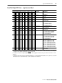
Additional Resources
These documents contain additional information concerning related
products from Rockwell Automation.
Resource
Description
PowerFlex 7-Class DPI (Drive Peripheral Interface) Network Communication Adapter Installation
Instructions, publication 20COMM-IN004
Information on installing PowerFlex® 20-COMM-x Network
Communication Adapters.
Connected Components Workbench website http://www.ab.com/support/abdrives/webupdate/
software.html, and online help (1)
Information on the Connected Components Workbench
software tool—and includes a link for free software download.
DriveExplorer website http://www.ab.com/drives/driveexplorer, and online help (1)
Information on using the DriveExplorer™ software tool.
DriveExecutive website http://www.ab.com/drives/drivetools,
and online help (1)
Information on using the DriveExecutive™ software tool.
PowerFlex 20-HIM-A3/-A5/-C3S/-C5S HIM Quick Reference, publication 20HIM-QR001
Information on using PowerFlex 20-HIM-A3, 20-HIM-A5,
20-HIM-C3S, and 20-HIM-C5S HIMs.
PowerFlex 20-HIM-A6/C6S HIM (Human Interface Module) User Manual, publication 20HIM-UM001
Information on installing and using PowerFlex 20-HIM-A6 and
20-HIM-C6S HIMs.
PowerFlex 70 User Manual, publication 20A-UM001
PowerFlex 70/700 Reference Manual, publication PFLEX-RM001
PowerFlex 70 Enhanced Control and 700 Vector Control Reference Manual, publication PFLEX-RM004
Information on installing and programming PowerFlex 70
standard control and enhanced control drives.
PowerFlex 700 Series A User Manual, publication 20B-UM001
PowerFlex 700 Series B User Manual, publication 20B-UM002
PowerFlex 70/700 Reference Manual, publication PFLEX-RM001
PowerFlex 70 Enhanced Control and 700 Vector Control Reference Manual, publication PFLEX-RM004
Information on installing and programming PowerFlex 700
standard control and vector control Series A drives, and
PowerFlex 700 vector control Series B drives.
PowerFlex 700H Installation Instructions, publication PFLEX-IN006
PowerFlex 700H Programming Manual, publication 20C-PM001
Information on installing and programming PowerFlex 700H
drives.
PowerFlex 20-COMM-P Profibus Adapter User Manual
Publication 20COMM-UM006B-EN-P
About This Manual
P-3
Resource
Description
PowerFlex 700S w/Phase I Control Installation Manual (Frames 1…6), publication 20D-IN024
PowerFlex 700S w/Phase I Control Installation Manual (Frames 9 and 10), publication PFLEX-IN006
PowerFlex 700S w/Phase I Control User Manual (All Frame Sizes), publication 20D-UM001
PowerFlex 700S w/Phase I Control Reference Manual, publication PFLEX-RM002
PowerFlex 700S w/Phase II Control Installation Manual (Frames 1…6), publication 20D-IN024
PowerFlex 700S w/Phase II Control Installation Manual (Frames 9…14), publication PFLEX-IN006
PowerFlex 700S w/Phase II Control Programming Manual (All Frame Sizes), publication 20D-PM001
PowerFlex 700S w/Phase II Control Reference Manual, publication PFLEX-RM003
Information on installing and programming PowerFlex 700S
drives.
PowerFlex 700L User Manual, publication 20L-UM001
Information on installing and programming PowerFlex 700L
Liquid-Cooled AC drives.
PowerFlex Digital DC Drive User Manual, publication 20P-UM001
Information on installing and programming PowerFlex Digital
DC drives.
Profibus Installation Guideline at http://www.profibus.com/
Information on the planning, installation, and techniques used
to implement a Profibus network.
Profibus Standard at http://www.profibus.com/
Information on Profibus standards and specifications.
SLC 500 Modular Hardware Style Installation and Operation Manual, publication 1747-6.21
Information on installing and operating the SLC 500 controller.
SLC 500 Instruction Set, publication 1747-RM001
Information on status file functions and instructions for ladder
logic programs.
(1)
The online help is installed with the software.
Documentation can be obtained online at http://
literature.rockwellautomation.com. To order paper copies of technical
documentation, contact your local Rockwell Automation distributor or sales
representative.
To find your local Rockwell Automation distributor or sales representative,
visit http://www.rockwellautomation.com/locations.
For information such as firmware updates or answers to drive-related
questions, go to the Drives Service & Support website at http://
www.ab.com/support/abdrives and click on the Downloads or
Knowledgebase link.
PowerFlex 20-COMM-P Profibus Adapter User Manual
Publication 20COMM-UM006B-EN-P
P-4
About This Manual
Notes:
PowerFlex 20-COMM-P Profibus Adapter User Manual
Publication 20COMM-UM006B-EN-P
Chapter 1
Getting Started
The adapter is intended for installation into a PowerFlex 7-Class drive and
is used for network communication.
Components
Topic
Page
Components
1-1
Features
1-2
Compatible Products
1-2
Required Equipment
1-3
Safety Precautions
1-5
Quick Start
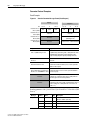
1-6
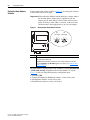
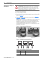
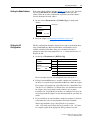
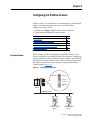
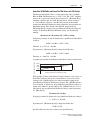
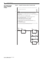
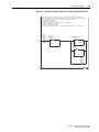
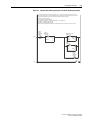
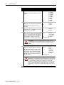
➊
➋
➍
➌
Item
Part
Description
➊
Status Indicators
Three status indicators that indicate the status of the DPI, adapter,
and network connection. See Chapter 7, Troubleshooting.
➋
DPI Connector
A 20-pin, single-row shrouded male header. An Internal Interface
cable is connected to this connector and a connector on the drive.
➌
Profibus Connector
A 9-pin, female D-sub connector to connect to the network.
➍
Node Address
Switches
Switches to set the node address. See Setting the Node Address
Switches on page 2-2.
PowerFlex 20-COMM-P Profibus Adapter User Manual
Publication 20COMM-UM006B-EN-P
1-2
Getting Started
Features
The features of the adapter include the following:
• Typical mounting in a PowerFlex 7-Class drive.
• Captive screws to secure and ground the adapter to the drive.
• Compatibility with various configuration tools to configure the adapter
and connected host drive, including the following tools:
–
–
–
–
PowerFlex HIM (Human Interface Module) on the drive, if available
Connected Components Workbench software, version 1.02 or later
DriveExplorer software, version 2.01 or later
DriveExecutive software, version 3.01 or later
• Switches to set a node address before applying power to the PowerFlex
drive. Or, you can disable the switches and use an adapter parameter to
set the node address.
• Status indicators that report the status of the drive communications, the
adapter, and network. They are visible when the drive cover is open or
closed.
• Parameter-configured I/O (Logic Command/Reference and up to four
pairs of Datalinks) to accommodate application requirements.
• Explicit Messaging support using the PROFIDRIVE Parameter Protocol.
• User-defined fault actions to determine how the adapter and connected
PowerFlex drive respond to the following:
– I/O messaging communication disruptions (Comm Flt Action)
– Controllers in idle mode (Idle Flt Action)
• Access to any PowerFlex drive and its connected peripherals on the
network to which the adapter is connected.
Compatible Products
At the time of publication, the adapter is compatible with the following
products:
• PowerFlex 70 drives with standard or enhanced control
• PowerFlex 700 drives with standard or vector control
• PowerFlex 700H drives
• PowerFlex 700S drives with Phase I or Phase II control
• PowerFlex 700L drives with 700 vector control or 700S control
• PowerFlex Digital DC drives
• SMC™ Flex smart motor controllers
• SMC-50 smart motor controllers
PowerFlex 20-COMM-P Profibus Adapter User Manual
Publication 20COMM-UM006B-EN-P
Getting Started
Required Equipment
1-3
Some of the equipment that is required for use with the adapter is shipped
with the adapter, but some you must supply yourself.
Equipment Shipped with the Adapter
When you unpack the adapter, verify that the package includes the
following:
❑ One 20-COMM-P adapter
❑ One 2.54 cm (1 in.) long and one 15.24 cm (6 in.) long Internal
Interface cable (only one cable is needed to connect the adapter to the
drive; for which cable to use, see Figure 2.2 on page 2-4)
❑ GSD file on digital media
❑ One PowerFlex 7-Class DPI (Drive Peripheral Interface) Network
Communication Adapter Installation Instructions, publication
20COMM-IN004
User-Supplied Equipment
To install and configure the adapter, you must supply the following:
❑ A small flathead screwdriver
❑ Profibus network cable
❑ One 9-pin, male D-Sub Profibus connector [Note: Profibus connectors
are available from a variety of sources and in various sizes. As such,
there may be mechanical limitations that prohibit the use of some
connectors. Phoenix Subcon Plus M1 (Part # 2761826) or ERNI
Profibus vertical (Node Part # 103658 and Termination Part # 103659),
are recommended for use with PowerFlex 7-Class drives.]
❑ Drive and adapter configuration tool, such as the following:
– PowerFlex 20-HIM-xx HIM
– Connected Components Workbench software, version 1.02 or later
Connected Components Workbench is the recommended
stand-alone software tool for use with PowerFlex drives. You can
obtain a free copy by:
• Internet download at http://www.ab.com/support/abdrives/
webupdate/software.html
• Requesting a DVD at http://www.ab.com/onecontact/controllers/
micro800/
Your local distributor may also have copies of the DVD available.
Connected Components Workbench software cannot be used to
configure SCANport-based drives or Bulletin 160 drives.
PowerFlex 20-COMM-P Profibus Adapter User Manual
Publication 20COMM-UM006B-EN-P
1-4
Getting Started
– DriveExplorer software, version 2.01 or later
This software tool has been discontinued and is now available as
freeware at http://www.ab.com/support/abdrives/webupdate/
software.html. There are no plans to provide future updates to this
tool and the download is being provided ‘as-is’ for users that lost
their DriveExplorer CD, or need to configure legacy products not
supported by Connected Components Workbench software.
– DriveExecutive software, version 3.01 or later
A Lite version of DriveExecutive software ships with RSLogix
5000, RSNetWorx MD, FactoryTalk AssetCentre, and
ItelliCENTER software. All other versions are purchasable items:
• 9303-4DTE01ENE Drive Executive software
• 9303-4DTS01ENE DriveTools SP Suite (includes
DriveExecutive and DriveObserver software)
• 9303-4DTE2S01ENE DriveExecutive software upgrade to
DriveTools SP Suite (adds DriveObserver software)
DriveExecutive software updates (patches, and so forth) can be
obtained at http://www.ab.com/support/abdrives/webupdate/
software.html. It is highly recommended that you periodically check
for and install the latest update.
❑ 1203-USB Serial Converter or 1203-SSS Serial Converter with
firmware revision 3.001 or later
❑ Profibus configuration software
❑ Controller configuration software
PowerFlex 20-COMM-P Profibus Adapter User Manual
Publication 20COMM-UM006B-EN-P
Getting Started
Safety Precautions
1-5
Please read the following safety precautions carefully.
!
!
!
!
!
!
!
ATTENTION: Risk of injury or death exists. The PowerFlex
drive can contain high voltages that can cause injury or death.
Remove all power from the PowerFlex drive, and then verify
power has been discharged before installing or removing the
adapter.
ATTENTION: Risk of injury or equipment damage exists. Only
personnel familiar with drive and power products and the
associated machinery should plan or implement the installation,
start up, configuration, and subsequent maintenance of the
product using an adapter. Failure to comply can result in injury
and/or equipment damage.
ATTENTION: Risk of equipment damage exists. The adapter
contains electrostatic discharge (ESD) sensitive parts that can be
damaged if you do not follow ESD control procedures. Static
control precautions are required when handling the adapter. If
you are unfamiliar with static control procedures, see Guarding
Against Electrostatic Damage, publication 8000-4.5.2.
ATTENTION: Risk of injury or equipment damage exists. If the
adapter is transmitting control I/O to the drive, the drive can fault
when you reset the adapter. Determine how your drive responds
before resetting an adapter.
ATTENTION: Risk of injury or equipment damage exists.
Parameters 9 - [Comm Flt Action] and 10 - [Idle Flt Action]
let you determine the action of the adapter and connected drive if
I/O communication is disrupted or the controller is idle. By
default, these parameters fault the drive. You can set these
parameters so that the drive continues to run, however, take
precautions to verify that the settings of these parameters do not
create a risk of injury or equipment damage. When
commissioning the drive, verify that your system responds
correctly to various situations (for example, a disconnected cable
or a faulted controller).
ATTENTION: Risk of injury or equipment damage exists.
When a system is configured for the first time, there can be
unintended or incorrect machine motion. Disconnect the motor
from the machine or process during initial system testing.
ATTENTION: Risk of injury or equipment damage exists. The
examples in this publication are intended solely for purposes of
example. There are many variables and requirements with any
application. Rockwell Automation does not assume responsibility
or liability (to include intellectual property liability) for actual
use of the examples shown in this publication.
PowerFlex 20-COMM-P Profibus Adapter User Manual
Publication 20COMM-UM006B-EN-P
1-6
Getting Started
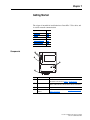
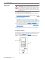
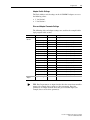
Quick Start
This section is provided to help experienced users quickly start using the
adapter. If you are unsure how to complete a step, refer to the referenced
chapter.
Step Action
See
1
Review the safety precautions for the adapter.
Throughout This Manual
2
Verify that the PowerFlex drive is properly installed.
Drive User Manual
3
Install the adapter.
b. Connect the adapter to the drive with the Internal Interface
cable.
PowerFlex 7-Class DPI
Network Communication
Adapter Installation
Instructions, publication
20COMM-IN004, and
c. Use the captive screws to secure and ground the adapter to
the drive.
Chapter 2,
Installing the Adapter
a. Verify that the PowerFlex drive is not powered.
d. Connect the adapter to the network with a Profibus cable.
4
Apply power to the adapter.
a. Verify that the adapter is installed correctly
Chapter 2,
Installing the Adapter
The adapter receives power from the drive.
b. Apply power to the drive.
The status indicators should be green. If they flash red, there
is a problem. See Chapter 7, Troubleshooting.
c. Configure and verify key drive parameters.
5
Configure the adapter for your application.
Set adapter parameters for the following functions as required
by your application:
Chapter 3,
Configuring the Adapter
• Node address
• I/O configuration
• Fault actions
6
Apply power to the Profibus master and other devices on the
network.
—
Verify that the master and network are installed properly and
functioning in accordance with Profibus standards.
7
Configure the scanner to communicate with the adapter.
Use a network tool for Profibus to configure the master on the
network to recognize the adapter and drive.
8
Create a ladder logic program.
Use a controller configuration tool to create a ladder logic
program that enables you to do the following:
• Control the connected drive, via the adapter, by using I/O.
• Monitor or configure the drive using explicit messages.
PowerFlex 20-COMM-P Profibus Adapter User Manual
Publication 20COMM-UM006B-EN-P
Chapter 4,
Configuring the Profibus
Scanner
Chapter 5,
Using the I/O
Chapter 6,
Using Explicit Messaging
Chapter 2
Installing the Adapter
This chapter provides instructions for installing the adapter in a PowerFlex
7-Class drive.
Topic
Page
Preparing for an Installation
2-1
Commissioning the Adapter
2-1
Setting the Node Address Switches
2-2
Connecting the Adapter to the Drive
2-3
Connecting the Adapter to the Network
2-6
Node Termination
2-7
Applying Power
2-8
Preparing for an Installation Before installing the adapter, verify that you have all required equipment.
See Required Equipment on page 1-3.
!
ATTENTION: Risk of equipment damage exists. The adapter
contains electrostatic discharge (ESD) sensitive parts that can be
damaged if you do not follow ESD control procedures. Static
control precautions are required when handling the adapter. If you
are unfamiliar with static control procedures, see Guarding
Against Electrostatic Damage, publication 8000-4.5.2.
Commissioning the Adapter To commission the adapter, you must set a unique node address on the
network. See Setting the Node Address Switches on page 2-2 or Setting the
Node Address on page 3-3 for details.
Important: New settings for some adapter parameters are recognized only
when power is applied to the adapter or it is reset. After you
change parameter settings, cycle power or reset the adapter.
PowerFlex 20-COMM-P Profibus Adapter User Manual
Publication 20COMM-UM006B-EN-P
2-2
Installing the Adapter
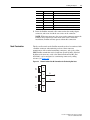
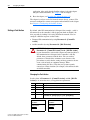
Setting the Node Address
Switches
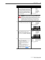
Set the adapter node address switches (Figure 2.1) by rotating the switches
to the desired value for each digit.
Important: Each node on the Profibus network must have a unique address.
Set the node address before power is applied because the
adapter uses the node address it detects when it first receives
power. To change a node address, you must set the new value
and then remove and reapply power to (or reset) the adapter.
Figure 2.1
Setting Adapter Node Address Switches
S2
(Tens Digit)
S3
(Ones Digit)
2 3
2 3
1
0
9
8
7
1
4
5 0
6
9
8
4
5
6
7
Setting
Description
0…99
The node address used by the adapter if the Node Address switches are enabled.
The default switch setting is 05.
Important: If the Node Address switches are set to ‘00’, the adapter uses the value
stored in Parameter 03 - [P-DP Addr Cfg] for the node address. See Setting the Node
Address on page 3-3.
The Node Address switch settings can be verified by viewing Parameter 04
- [P-DP Addr Actual] or Diagnostic Device Item numbers 27 and 28
(page 7-4) with any of the following drive configuration tools:
•
•
•
•
PowerFlex 20-COMM-P Profibus Adapter User Manual
Publication 20COMM-UM006B-EN-P
PowerFlex HIM
Connected Components Workbench software, version 1.02 or later
DriveExplorer software, version 2.01 or later
DriveExecutive software, version 3.01 or later
Installing the Adapter
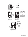
Connecting the Adapter to
the Drive
!
2-3
ATTENTION: Risk of injury or death exists. The PowerFlex
drive may contain high voltages that can cause injury or death.
Remove power from the drive, and then verify power has been
discharged before installing or removing the adapter.
1. Remove power from the drive.
2. Use static control precautions.
3. Remove or open the drive cover.
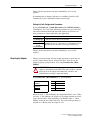
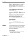
4. Connect the Internal Interface cable to the DPI port on the drive and
then to the DPI connector on the adapter (see Figure 2.2).
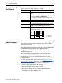
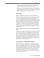
5. Secure and ground the adapter to the drive (see Figure 2.3) by doing the
following:
– On a PowerFlex 70 drive, fold the Internal Interface cable behind the
adapter and mount the adapter on the drive using the four captive
screws.
– On a PowerFlex 700, PowerFlex 700H, or PowerFlex 700S drive,
mount the adapter on the drive using the four captive screws.
Important: Tighten all screws to properly ground the adapter.
Recommended torque is 0.9 N•m (8.0 lb•in).
PowerFlex 20-COMM-P Profibus Adapter User Manual
Publication 20COMM-UM006B-EN-P
2-4
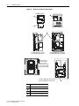
Installing the Adapter
Figure 2.2
DPI Ports and Internal Interface Cables
20-COMM-P Adapter
➊
➋
➌
PowerFlex 70 - All Frames
➍
PowerFlex 700 Frames 0 and 1
PowerFlex 700S Frames 0 and 1
PowerFlex 700 Frames 2 and Larger
PowerFlex 700S Frames 2 through 6
HIM panel opens for
access to the DPI
interface. To open
panel, remove screws
on left side of the HIM
panel and swing open.
PowerFlex 700H Frames 9 and Larger
PowerFlex 700S Frames 9 and Larger
PowerFlex 20-COMM-P Profibus Adapter User Manual
Publication 20COMM-UM006B-EN-P
Item
Description
➊
15.24 cm (6 in.) Internal Interface cable
➋
DPI Connector
➌
Profibus connector
➍
2.54 cm (1 in.) Internal Interface cable
X2
X1
➍
Installing the Adapter
Figure 2.3
2-5
Mounting and Grounding the Adapter
Drive
0.9 N•m
(8.0 lb•in)
4 Places
Adapter
Internal Interface Cable
folded behind the adapter
and in front of the drive.
Ground Tab Detail
PowerFlex 70 - All Frame Sizes
(Adapter mounts in drive.)
0.9 N•m
(8.0 lb•in)
4 Places
PowerFlex 700 Frames 0 and 1
PowerFlex 700S Frames 0 and 1
(Adapter mounts on door.)
Verify metal ground tab is bent 90° and
is under the adapter before tightening
screw. After tightening the screw, verify
continuity exists between the head of
the screw and drive ground.
PowerFlex 700 Frames 2 and Larger
PowerFlex 700S Frames 2 through 6
(Adapter mounts in drive.)
Ground Tab Detail
X2
X1
0.9 N•m
(8.0 lb•in)
4 Places
PowerFlex 700H Frames 9 and Larger
PowerFlex 700S Frames 9 and Larger
(Adapter mounts behind HIM panel.)
Verify metal ground tab is bent 90° and
is under the adapter before tightening
screw. After tightening the screw, verify
continuity exists between the head of
the screw and drive ground.
PowerFlex 20-COMM-P Profibus Adapter User Manual
Publication 20COMM-UM006B-EN-P
2-6
Installing the Adapter
Connecting the Adapter to
the Network
ATTENTION: Risk of injury or death exists. The PowerFlex
drive can contain high voltages that can cause injury or death.
Remove power from the drive, and then verify power has been
discharged before installing or removing the adapter.
!
1. Remove power from the drive.
2. Use static control precautions.
3. Route the Profibus network cable through the bottom of the PowerFlex
drive (see Figure 2.3).
4. Connect the Profibus connector to the network cable (see Figure 2.4,
Figure 2.5, and Table 2.A.)
NOTE: Profibus connectors are available from a variety of sources and
in various sizes. As such, there may be mechanical limitations that
prohibit the use of some connectors. Phoenix Subcon Plus M1 (Part #
2761826) or ERNI Profibus vertical (Node Part # 103658 and
Termination Part # 103659 connectors), are recommended for use with
PowerFlex 7-Class drives.
Figure 2.4
Phoenix Subcon and ENRI Connectors
Phoenix Subcon Connector
Figure 2.5
B A
ENRI Connector
PROFIBUS Connector Network Diagram
B A
B A
B A
B A
B A
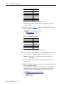
Table 2.A Adapter PROFIBUS Connector Pin Layout
PowerFlex 20-COMM-P Profibus Adapter User Manual
Publication 20COMM-UM006B-EN-P
Terminal
Signal
Function
Housing
Shield
—
1
Not connected
—
2
Not connected
—
Installing the Adapter
Terminal
Signal
Function
3
B-LINE
Positive RxD/TxD, according to RS485 specification
4
RTS
Request to send
5
GND BUS
Isolated GND from bus
6
+5V BUS
Isolated +5V from bus
7
Not connected
—
8
A-LINE
Negative RxD/TxD, according to RS485 specification
9
Not connected
—
2-7
5. Insert the Profibus network cable connector into the mating adapter
connector, and secure it with the two screws on the connector.
NOTE: With some connectors, the screws on the connector connect the
Profibus cable earth/screen to the metal of the socket. With some
installations, Profibus will not operate without this connection.
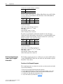
Node Termination
The first and last node on the Profibus network needs to be terminated with
a Profibus connector and terminating resistors. Some connector
manufacturers offer standard terminating connectors, such as the yellow
ERNI Profibus termination vertical connector (Part # 103659). Standard
Profibus node connectors, such as the Phoenix Subcon Plus M1 (Part
#2761826), can be configured as a terminating connector by adding
resistors (see Figure 2.6).
Figure 2.6
390
ohm
Phoenix Subcon Plus M1 Connection for Terminating Resistors
6
3
B
220
ohm
8
390
ohm
A
5
PowerFlex 20-COMM-P Profibus Adapter User Manual
Publication 20COMM-UM006B-EN-P
2-8
Installing the Adapter
Applying Power
!
ATTENTION: Risk of equipment damage, injury, or death
exists. Unpredictable operation can occur if you fail to verify that
parameter settings are compatible with your application. Verify
that settings are compatible with your application before applying
power to the drive.
1. Install the drive cover or close the drive door.
2. Verify that the adapter has a unique node address on the network.
If a new address is needed, reset the node address switches (see Setting
the Node Address Switches on page 2-2).
3. Apply power to the drive.
The adapter receives its power from the connected drive. When you
apply power to the adapter for the first time, its topmost ‘PORT’ status
indicator should be steady green or flashing green after an initialization.
If it is red, there is a problem. See Chapter 7, Troubleshooting.
4. If the node address switches are set to ‘00’, use a configuration tool to
set the node address parameters in the adapter (see Setting the Node
Address on page 3-3).
5. Apply power to the master device and other devices on the network.
Start-Up Status Indications
Status indicators for the drive and communication adapter can be viewed on
the front of the drive (Figure 2.7) after power has been applied. Possible
start-up status indications are shown in Table 2.B.
Figure 2.7
Drive and Adapter Status Indicators (location on drive may vary)
PORT
MOD
➋
NET A
NET B
➊
STS
PowerFlex 20-COMM-P Profibus Adapter User Manual
Publication 20COMM-UM006B-EN-P
Installing the Adapter
2-9
Table 2.B Drive and Adapter Start-Up Status Indications
Item Name
Color
State
Description
Drive STS Indicator
➊
STS
(Status)
Green
Yellow
Red
Flashing
Drive ready but not running, and no faults are present.
Steady
Drive running, no faults are present.
Flashing,
drive stopped
An inhibit condition exists – the drive cannot be
started. Check drive Parameter 214 - [Start Inhibits].
Flashing,
drive running
An intermittent type 1 alarm condition is occurring.
Check drive Parameter 211 - [Drive Alarm 1].
Steady,
drive running
A continuous type 1 alarm condition exists. Check
drive Parameter 211 - [Drive Alarm 1].
Flashing
A fault has occurred.
Steady
A non-resettable fault has occurred.
Adapter Status Indicators
➋
PORT
MOD
Green
Green
Flashing
Normal operation. The adapter is establishing an I/O
connection to the drive. It will turn steady green or red.
Steady
Normal operation. The adapter is properly connected
and communicating with the drive.
Flashing
Normal operation. The adapter is operating but is not
transferring I/O data to a controller.
Steady
Normal operation. The adapter is operating and
transferring I/O data to a controller.
NET A
Green
Steady
Normal operation. The adapter is properly connected
and Bus is on-line.
NET B
—
—
Not used by Profibus adapter.
For more details on status indicator operation, see page 7-2 and page 7-3.
Configuring and Verifying Key Drive Parameters
The PowerFlex 7-Class drive can be separately configured for the control
and Reference functions in various combinations. For example, you could
set the drive to have its control come from a peripheral or terminal block
with the Reference coming from the network. Or you could set the drive to
have its control come from the network with the Reference coming from
another peripheral or terminal block. Or you could set the drive to have both
its control and Reference come from the network.
The following steps in this section assume that the drive will receive the
Logic Command and Reference from the network.
1. Use drive Parameter 090 - [Speed Ref A Sel] to set the drive speed
Reference to ‘22’ (DPI Port 5).
2. If hard-wired discrete digital inputs are not used to control the drive,
verify that unused digital input drive Parameters 361 - [Dig In1 Sel] and
362 - [Dig In2 Sel] are set to ‘0’ (Not Used).
PowerFlex 20-COMM-P Profibus Adapter User Manual
Publication 20COMM-UM006B-EN-P
2-10
Installing the Adapter
3. Verify that drive Parameter 213 - [Speed Ref Source] is reporting that
the source of the Reference to the drive is ‘22’ (DPI Port 5).
This ensures that any Reference commanded from the network can be
monitored by using drive Parameter 002 - [Commanded Speed]. If a
problem occurs, this verification step provides the diagnostic capability
to determine whether the drive/adapter or the network is the cause.
PowerFlex 20-COMM-P Profibus Adapter User Manual
Publication 20COMM-UM006B-EN-P
Chapter 3
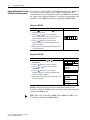
Configuring the Adapter
This chapter provides instructions and information for setting the
parameters to configure the adapter.
Topic
Page
Configuration Tools
3-1
Using the PowerFlex 7-Class HIM to Access Parameters
3-2
Setting the Node Address
3-3
Setting the I/O Configuration
3-3
Setting a Fault Action
3-4
Resetting the Adapter
3-5
Viewing the Adapter Status Using Parameters
3-6
Updating the Adapter Firmware
3-6
For a list of parameters, refer to Appendix B, Adapter Parameters. For
definitions of terms in this chapter, see the Glossary.
Configuration Tools
The adapter stores parameters and other information in its own nonvolatile
storage (NVS) memory. You must, therefore, access the adapter to view and
edit its parameters. The following tools can be used to access the adapter
parameters.
Tool
See
PowerFlex 7-Class HIM
page 3-2
Connected Components Workbench
software, version 1.02 or later
http://www.ab.com/support/abdrives/webupdate/
software.html, or online help (installed with the software)
DriveExplorer software,
version 2.01 or later
http://www.ab.com/drives/driveexplorer, or
DriveExplorer online help (installed with the software)
DriveExecutive software,
version 3.01 or later
http://www.ab.com/drives/drivetools, or
DriveExecutive online help (installed with the software)
PowerFlex 20-COMM-P Profibus Adapter User Manual
Publication 20COMM-UM006B-EN-P
3-2
Configuring the Adapter
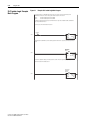
Using the PowerFlex 7-Class If your drive has either an LED or LCD HIM (Human Interface Module), it
can be used to access parameters in the adapter as shown below. We
HIM to Access Parameters
recommend that you read through the steps for your HIM before performing
the sequence. For additional information, see the drive documentation or the
PowerFlex 7-Class HIM Quick Reference, publication 20HIM-QR001.
Using an LED HIM
Step
Example Screens
1. Press the ALT key and then the Device
display the Device Screen.
Sel
(Sel) key to
2. Press the
or
key to scroll to the adapter.
Letters represent files in the drive, and numbers represent
ports. The adapter is usually connected to port 5.
3. Press the
(Enter) key to enter your selection.
A parameter database is constructed, and then the first
parameter is displayed.
4. Edit the parameters using the same techniques that you use
to edit drive parameters.
Using an LCD HIM
Step
Example Screens
1. In the main menu, press the
Device Select.
2. Press the
or
key to scroll to
(Enter) key to enter your selection.
3. Press the
or
(20-COMM-P).
key to scroll to the adapter
4. Press the
(Enter) key to select the adapter.
A parameter database is constructed, and then the main
menu for the adapter is displayed.
5. Edit the parameters using the same techniques that you use
to edit drive parameters.
F-> Stopped
Auto
0.00
Hz
Main Menu:
Diagnostics
Parameter
Device Select
Port 5 Device
20-COMM-P
Main Menu:
Diagnostics
Parameter
D i S l t
NOTE: All configuration procedures throughout this chapter use the
PowerFlex 7-Class LCD HIM to access parameters in the adapter and show
example LCD HIM screens.
TIP: When using a PowerFlex 20-HIM-A6 or 20-HIM-C6S HIM, see its
User Manual, publication 20-HIM-UM001.
PowerFlex 20-COMM-P Profibus Adapter User Manual
Publication 20COMM-UM006B-EN-P
Configuring the Adapter
Setting the Node Address
3-3
If the adapter Node Address switches (Figure 2.1) are set to ‘00’ (Program)
the value of Parameter 03 - [P-DP Addr Cfg] determines the node
address. When in any other combination of positions, the Node Address
switches determine the node address.
1. Set the value of Parameter 03 - [CN Addr Cfg] to a unique node
address.
Port 5 Device
20-COMM-P
Parameter #: 03
P-DP Addr Cfg
1
Default = 01
0 <> 126
2. Reset the adapter (see Resetting the Adapter on page 3-5).
Setting the I/O
Configuration
The I/O configuration determines the data that is sent to and from the drive.
Logic Command/Status, Reference/Feedback, and Datalinks may be
enabled or disabled. (Datalinks allow you to read/write directly to
parameters in the drive using implicit I/O.) A ‘1’ enables the I/O and a ‘0’
disables the I/O.
1. Set the bits in Parameter 11 - [DPI I/O Cfg].
Port 5 Device
20-COMM-P
Parameter #: 11
DPI I/O Cfg
xxxxxxxxxxx0 0 0 0 1
Cmd/Ref
b00
Bit
Description
0
Logic Command/Reference (Default)
1
Datalink A
2
Datalink B
3
Datalink C
4
Datalink D
5…15
Not Used
Bit 0 is the right-most bit. It is highlighted above and equals ‘1’.
2. If Logic Command/Reference is enabled, configure the parameters in
the drive to accept the Logic Command and Reference from the adapter.
For example, set Parameter 90 - [Speed Ref A Sel] in a PowerFlex 70 or
700 drive to ‘22’ (DPI Port 5) so that the drive uses the Reference from
the adapter. Also, verify that the mask parameters (for example,
Parameter 276 - [Logic Mask]) in the drive are configured to receive the
desired logic from the adapter. See the documentation for your drive for
details.
3. If you enabled one or more Datalinks, configure parameters in the drive
to determine the source and destination of data in the Datalinks.
When using Datalinks, up to 8 drive [Data In xx] parameters
(300…307) and/or up to 8 [Data Out xx] parameters (310…317) must
be assigned to point to the appropriate drive parameters for your
PowerFlex 20-COMM-P Profibus Adapter User Manual
Publication 20COMM-UM006B-EN-P
3-4
Configuring the Adapter
application. Also, verify that the Profibus adapter is the only adapter
using the enabled Datalinks. See Chapter 4 for an example.
4. Reset the adapter (see Resetting the Adapter on page 3-5).
The adapter is ready to receive I/O from the master (that is, scanner). You
must now configure the scanner to recognize and transmit I/O to the adapter.
See Chapter 4, Configuring the Profibus Scanner.
Setting a Fault Action
By default, when I/O communication is disrupted (for example, a cable is
disconnected) or the controller is idle (in program mode or faulted), the
drive responds by faulting if it is using I/O from the network. You can
configure a different response to these faults:
• Disrupted I/O communication by using Parameter 9 - [Comm Flt
Action]
• An idle controller by using Parameter 10 - [Idle Flt Action]
!
ATTENTION: Risk of injury or equipment damage exists.
Parameters 9 - [Comm Flt Action] and 10 - [Idle Flt Action]
let you determine the action of the adapter and connected drive if
I/O communication is disrupted or the controller is idle. By
default, these parameters fault the drive. You can set these
parameters so that the drive continues to run, however, take
precautions to verify that the settings of these parameters do not
create a risk of injury or equipment damage. When
commissioning the drive, verify that your system responds
correctly to various situations (for example, a disconnected cable
or faulted controller).
Changing the Fault Action
Set the values of Parameters 9 - [Comm Flt Action] and 10 - [Idle Flt
Action] to an action that meets your application requirements.
Value
Action
Description
0
Fault
The drive is faulted and stopped. (Default)
1
Stop
The drive is stopped, but not faulted.
2
Zero Data
The drive is sent ‘0’ values for data. This does not command a stop.
3
Hold Last
The drive continues in its present state.
4
Send Flt Cfg
The drive is sent the data that you set in the fault configuration parameters
(Parameters 13 - [Flt Cfg Logic] through 22 - [Flt Cfg D2 In]).
Port 5 Device
20-COMM-P
Parameter #: 9
Comm Flt Action
0
Fault
PowerFlex 20-COMM-P Profibus Adapter User Manual
Publication 20COMM-UM006B-EN-P
Port 5 Device
20-COMM-P
Parameter #: 10
Idle Flt Action
0
Fault
Configuring the Adapter
3-5
Changes to these parameters take effect immediately. A reset is not
required.
If communication is disrupted and then is re-established, the drive will
automatically receive commands from the network again.
Setting the Fault Configuration Parameters
If you set Parameter 9 - [Comm Flt Action] or 10 - [Idle Flt Action] to
‘Send Flt Cfg’, the values in the following parameters are sent to the drive
after an I/O communication fault and/or idle fault occurs. You must set
these parameters to values required by your application.
Parameter
Description
13 - [Flt Cfg Logic] A 16-bit value sent to the drive for Logic Command.
14 - [Flt Cfg Ref]
A 32-bit value (0…4294967295) sent to the drive as a Reference or Datalink.
15 - [Flt Cfg x1 In]
through
22 - [Flt Cfg x2 In]
Important: If the drive uses a 16-bit Reference or 16-bit Datalinks, the most
significant word of the value must be set to zero (0) or a fault will occur.
Changes to these parameters take effect immediately. A reset is not
required.
Resetting the Adapter
Changes to switch settings and some adapter parameters require that you
reset the adapter before the new settings take effect. You can reset the
adapter by power cycling the drive or by using Parameter 08 - [Reset
Module].
!
ATTENTION: Risk of injury or equipment damage exists. If the
adapter is transmitting control I/O to the drive, the drive can fault
when you reset the adapter. Determine how your drive will
respond before resetting a connected adapter.
Set Parameter 08 - [Reset Module] to ‘1’ (Reset Module).
Port 5 Device
20-COMM-P
Parameter #: 08
Reset Module
1
Reset Module
Value
Description
0
Ready (Default)
1
Reset Module
2
Set Defaults
When you enter ‘1’ (Reset Module), the adapter immediately resets. When
you enter ‘2’ (Set Defaults), the adapter sets all adapter parameters to their
factory-default values. After performing a Set Defaults, enter ‘1’ (Reset
Module) so that the new values take effect. The value of this parameter is
restored to ‘0’ (Ready) after the adapter is reset.
PowerFlex 20-COMM-P Profibus Adapter User Manual
Publication 20COMM-UM006B-EN-P
3-6
Configuring the Adapter
Viewing the Adapter Status
Using Parameters
The following parameters provide information about the status of the
adapter. You can view these parameters at any time.
Parameter
Description
04 - [P-DP Addr Actual]
The node address used by the adapter. This will be one of the following
values:
• The address set by the rotary switches.
• The value of Parameter 03 - [P-DP Addr Cfg].
• An old address of the switches or parameter if they have been
changed and the adapter has not been reset.
Cmd/Ref
The Reference/Feedback and Datalinks used by the adapter. This value
is the same as Parameter 13 - [DPI I/O Cfg] unless the parameter was
changed and the adapter was not reset.
Datalink A
12 - [DPI I/O Active]
Datalink B
The size of the Datalinks. It will either be 16 bits or 32 bits. It is set in the
drive and the adapter automatically uses the correct size.
Datalink C
07 - [Datalink Size]
Datalink D
The size of the Reference/Feedback. It will either be 16 bits or 32 bits. It
is set in the drive and the adapter automatically uses the correct size.
Not Used
06 - [Ref/Fdbk Size]
Not Used
The Profibus data rate used by the adapter.
Not Used
05 - [P-DP Rate Actual]
Default
x
x
x
0
0
0
0
1
Bit
7
6
5
4
3
2
1
0
Bit
Definition
Updating the Adapter
Firmware
0 = I/O Disabled
1 = I/O Enabled
The adapter firmware can be updated over the network or serially through a
direct connection from a computer to the drive using a 1203-USB or
1203-SSS serial converter.
When updating firmware over the network, you can use the Allen-Bradley
ControlFLASH software tool, the built-in update capability of
DriveExplorer Lite or Full software, or the built-in update capability of
DriveExecutive software.
When updating firmware through a direct serial connection from a
computer to a drive, you can use the same Allen-Bradley software tools
described above, or you can use HyperTerminal software set to the
X-modem protocol.
To obtain a firmware update for this adapter, go to http://www.ab.com/
support/abdrives/webupdate. This website contains all firmware update files
and associated Release Notes that describe the following items:
• Firmware update enhancements and anomalies
• How to determine the existing firmware revision
• How to update firmware using ControlFLASH, DriveExplorer,
DriveExecutive, or HyperTerminal software
PowerFlex 20-COMM-P Profibus Adapter User Manual
Publication 20COMM-UM006B-EN-P
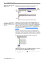
Chapter 4
Configuring the Profibus Scanner
Profibus scanners are available from several manufacturers, including SST.
Chapter 4 provides instructions on how to use the SST Profibus
configuration software tool to:
• Install the 20-COMM-P GSD file in the software tool library
• Configure the SST-PFB-SLC Profibus Scanner
Example Network
Topic
Page
Example Network
4-1
SST Profibus Configuration Software Tool
4-2
Installing the 20-COMM-P GSD File Into Software Tool Library
4-2
Configuring the SST-PFB-SLC Profibus Scanner
4-4
GSD Diagnostic Messages
4-13
In this example, we will be configuring two PowerFlex 70 drives, to be
Station 1 and Station 2 on a Profibus network. This will be the configuration
used throughout the manual, including the ladder examples. Apart from the
node address and scanner mapping, they will have identical configurations.
This chapter describes the steps to configure a simple network like the
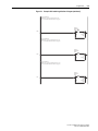
example shown in Figure 4.1.
Figure 4.1
Example Profibus Network
COMM LED
SYS LED
Config Port
Front Label
PROFIBUS
Port
Station 0
PROFIBUS Network
PowerFlex 70 Drive
Station 1
PowerFlex 70 Drive
Station 2
PowerFlex 20-COMM-P Profibus Adapter User Manual
Publication 20COMM-UM006B-EN-P
4-2
Configuring the Profibus Scanner
SST Profibus Configuration
Software Tool
SST Profibus scanners come with a software tool for configuring the
scanner. An example software tool window is shown below.
Device
Library
Pane
Network
Configuration
Pane
Online
Browse
Pane
Installing the 20-COMM-P
GSD File Into Software Tool
Library
GSD files are used by software tools to configure the network, that is, to
map and define the I/O in a Profibus scanner. A GSD file is required for
each type of adapter on the network. For example, the 20-COMM-P adapter
GSD file is ‘A_B_0572.gsd’ and a copy of the file is provided on digital
media with each 20-COMM-P adapter. The file can also be downloaded
from the Rockwell website at http://www.ab.com/support/abdrives/
webupdate.
Follow the steps outlined below only when a new GSD file needs to be
added to the SST Profibus Configuration Software Tool. Typically, this is
only done once, after the software tool is initially installed or if configuring
a 20-COMM-P on the network for the very first time with this software tool.
The software tool comes with standard data files as shown below.
Additional data files, such as the 20-COMM-P adapter GSD file, need to be
added to configure the 20-COMM-P adapter in the scanner.
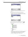
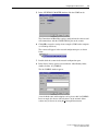
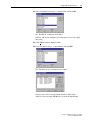
1. Click the ‘New Device’ icon
library tool.
PowerFlex 20-COMM-P Profibus Adapter User Manual
Publication 20COMM-UM006B-EN-P
to add the GSD file to the software
Configuring the Profibus Scanner
4-3
The ‘Add PROFIBUS devices’ Applet window appears.
A prompt appears for the location to add the Profibus data files to the
library.
2. Find the directory location of the data file(s) you wish to add.
Typically, the source location is a floppy disk in drive A. The
‘A_B_0572.gsd’ file shown below is the GSD file for the 20-COMM-P
adapter.
3. Select ‘A_B_0572.gsd’ for the 20-COMM-P adapter and click Open.
4. In the treeview in the Device Library pane, click the ‘+’ sign of the
Slaves folder.
The software tool will automatically create an Allen-Bradley sub-folder
(in the Slaves folder) if it does not already exist. The 20-COMM-P is
now shown in the library and the software tool is now ready to
configure a 20-COMM-P adapter on a Profibus network.
PowerFlex 20-COMM-P Profibus Adapter User Manual
Publication 20COMM-UM006B-EN-P
4-4
Configuring the Profibus Scanner
Configuring the
SST-PFB-SLC Profibus
Scanner
The instructions in this section describe how to configure the SST-PFB-SLC
scanner using the SST Profibus Configuration Software Tool. In our
example, the Profibus network consists of a SLC master and two PowerFlex
70 drives. The ladder examples in this manual use the following
configuration:
• Logic Command/Status and Reference/Feedback enabled
• Datalinks A, B, C, and D enabled
• Parameter Access enabled (used to perform explicit messaging)
Important: The SLC processor must be in Program mode to configure the
scanner.
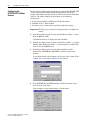
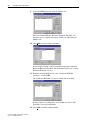
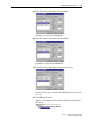
1. In the Device Library pane treeview, click the Masters folder ‘+’ sign to
open the SST sub-folder.
Available DP masters are displayed in this sub-folder.
2. In the Device Library pane treeview, click the Slaves folder ‘+’ sign and
then the Allen-Bradley sub-folder ‘+’ sign to display the available DP
slaves or the 20-COMM-P slave.
3. In the Device Library pane treeview under the Masters folder,
double-click ‘SST-PFB-SLC MASTER’ to add the scanner to the
network.
A user-defined name and description can be given to the scanner. In our
example, the scanner will be Station 0 on the network.
4. In the SST-PFB-SLC MASTER window, click the Parameters tab to
view the Scan Cycle Times.
In our example, use the default settings as shown below.
PowerFlex 20-COMM-P Profibus Adapter User Manual
Publication 20COMM-UM006B-EN-P
Configuring the Profibus Scanner
4-5
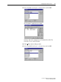
5. In the SST-PFB-SLC MASTER window, click the COM Port tab.
The Connection and Baud Rate settings configure how the software tool
will communicate with the CONFIG RS232 port on the scanner.
6. Click OK to accept the settings in our example (COM1 on the computer
at 115200 bps baud rate).
The scanner will appear in the network configuration pane as shown
below.
7. Double-click the scanner in the network configuration pane.
8. In the Device Library pane treeview under the Allen-Bradley folder,
double-click the ‘20_COMM_P’.
The 20-COMM-P window appears.
A user-defined name and description can be given to this 20-COMM-P.
In our example, this device will be Station 1 on the network. Other
stations may be chosen by using the Station pull-down menu.
PowerFlex 20-COMM-P Profibus Adapter User Manual
Publication 20COMM-UM006B-EN-P
4-6
Configuring the Profibus Scanner
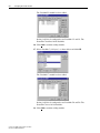
9. In the 20-COMM-P window, click the Modules tab.
The Logic Command/Status, Reference/Feedback, Datalinks, and
Parameter Access (explicit messaging) modules are added using the
Modules tab.
10. Click Add to view the choice of modules.
In our example, Station 1 will be controlled using Logic Command/
Status and Reference/Feedback. The PowerFlex 70 drive uses a 16-bit
Reference/Feedback (2 bytes).
11. From the Available Modules list, select ‘Ctrl/Stat & Ref/Fdbk
(2+2bytes)’ and click OK.
The ‘Ctrl/Stat & Ref/Fdbk (2+2 bytes)’ module has been added.
Station 1 will also be configured to use Datalinks A1 and A2. The
PowerFlex 70 uses 16-bit Datalinks.
12. Click Add to continue adding modules.
PowerFlex 20-COMM-P Profibus Adapter User Manual
Publication 20COMM-UM006B-EN-P
Configuring the Profibus Scanner
4-7
13. Select ‘Datalink A (2x2 bytes)’ as shown below and click OK.
The ‘Datalink A’ module has been added.
Station 1 will also be configured to use Datalinks B1 and B2. The
PowerFlex 70 uses 16-bit Datalinks.
14. Click Add to continue adding modules.
15. Select ‘Datalink B (2x2 bytes)’ as shown below and click OK.
PowerFlex 20-COMM-P Profibus Adapter User Manual
Publication 20COMM-UM006B-EN-P
4-8
Configuring the Profibus Scanner
The ‘Datalink B’ module has been added.
Station 1 will also be configured to use Datalinks C1 and C2. The
PowerFlex 70 utilizes 16-bit Datalinks.
16. Click Add to continue adding modules.
17. Select ‘Datalink C (2x2 bytes)’ as shown below and click OK.
The ‘Datalink C’ module has been added.
Station 1 will also be configured to use Datalinks D1 and D2. The
PowerFlex 70 uses 16-bit Datalinks.
18. Click Add to continue adding modules.
PowerFlex 20-COMM-P Profibus Adapter User Manual
Publication 20COMM-UM006B-EN-P
Configuring the Profibus Scanner
4-9
19. Select ‘Datalink D (2x2 bytes)’ as shown below and click OK.
The ‘Datalink D’ module has been added.
Station 1 will also be configured to use Parameter Access for explicit
messaging.
20. Click Add to continue adding modules.
21. Select ‘Parameter Access’ as shown below and click OK.
The ‘Parameter Access’ module has been added.
Settings can be chosen to map Station modules to SLC master
addresses. In our example, M1/M0 files are used for Input/Output.
PowerFlex 20-COMM-P Profibus Adapter User Manual
Publication 20COMM-UM006B-EN-P
4-10
Configuring the Profibus Scanner
22. In the 20-COMM-P window, click the SLC Address tab.
Note that Reference/Feedback (Ctrl/Stat & Ref/Fdbk) starts at word 0.
23. In the SLC Address Tab window, select Datalink A.
Datalink A is at word 2 in the M1/M0 files.
24. In the SLC Address Tab window, select Datalink B.
Datalink B is at word 4 in the M1/M0 files.
PowerFlex 20-COMM-P Profibus Adapter User Manual
Publication 20COMM-UM006B-EN-P
Configuring the Profibus Scanner
4-11
25. In the SLC Address Tab window, select Datalink C.
Datalink C is at word 6 in the M1/M0 files.
26. In the SLC Address Tab window, select Datalink D.
Datalink D is at word 8 in the M1/M0 files.
27. In the SLC Address Tab window, select Parameter Access.
Parameter Access starts at word 10 in the M1/M0 files. It uses 4 words
(10…13).
28. Click OK when finished.
Station 1 is now displayed in the network configuration pane under its
SLC master.
PowerFlex 20-COMM-P Profibus Adapter User Manual
Publication 20COMM-UM006B-EN-P
4-12
Configuring the Profibus Scanner
Station 1 is configured as follows.
Module
M1/M0 Word
Ctrl/Stat & Ref Fdbk
0
Datalink A
2
Datalink B
4
Datalink C
6
Datalink D
8
Parameter Access
10
Note that Station 1 occupies 14 words (0…13).
The same steps used to configure Station 1 will be used again to
configure Station 2.
29. Starting at step 8 on page 4-5, configure the SST-PFB-SLC Profibus
Master - Station 2.
Station 2 is configured as follows.
Module
M1/M0 Offset
Ctrl/Stat & Ref Fdbk
14
Datalink A
16
Datalink B
18
Datalink C
20
Datalink D
22
Parameter Access
24
Note that Station 2 occupies 14 words (14…27).
30. Connect COM1 on the computer to the CONFIG RS232 port on the
scanner using the null modem cable provided with the scanner.
Important: The processor needs to be in Program mode before
proceeding.
31. In the network configuration pane, right-click the SLC master and
choose ‘Connect’.
32. Right-click the SLC master again in the network configuration pane and
choose ‘Load Configuration’.
If a minimum cycle time attention window pops up, click OK to
continue. After the configuration has been loaded into the scanner,
‘Configured Program’ will be displayed in the message window.
PowerFlex 20-COMM-P Profibus Adapter User Manual
Publication 20COMM-UM006B-EN-P
Configuring the Profibus Scanner
4-13
33. From the SST PROFIBUS Configuration Software Tool window, select
File > Save As to save the file as a unique file name.
The configuration of the SLC Master scanner is now complete. Note
that cycling power to the scanner is recommended.
Configuration Summary for Example
M1/M0 Addressing
GSD Diagnostic Messages
20-COMM-P Adapter
Station 1 Word
Station 2 Word
Logic Command / Status
0
14
Reference / Feedback
1
15
Datalink A1
2
16
Datalink A2
3
17
Datalink B1
4
18
Datalink B2
5
19
Datalink C1
6
20
Datalink C2
7
21
Datalink D1
8
22
Datalink D2
9
23
Parameter Access
10…13
24…27
In the case of an invalid GSD module configuration, the peripheral will send
one of the following messages.
Fault
Description
No Ctrl/Stat & Ref/Fdbk
The Ctrl/Stat & Ref/Fdbk module must always be used and placed
first in the configuration.
Module used more than once
A GSD module has been used more than once.
Not supported module
An unrecognized module has been used in the configuration.
PowerFlex 20-COMM-P Profibus Adapter User Manual
Publication 20COMM-UM006B-EN-P
4-14
Configuring the Profibus Scanner
Notes:
PowerFlex 20-COMM-P Profibus Adapter User Manual
Publication 20COMM-UM006B-EN-P
Chapter 5
Using the I/O
This chapter provides information and examples that explain how to
control, configure, and monitor a PowerFlex 7-Class drive using the
configured I/O.
Topic
Page
About I/O Messaging
5-1
Understanding the I/O Image
5-2
Using Logic Command/Status
5-4
Using Reference/Feedback
5-4
Using Datalinks
5-6
SLC Controller Example Ladder Logic Program Information
5-8
SLC Ladder Logic Example Main Program
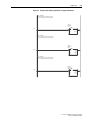
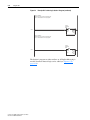
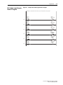
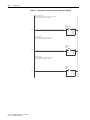
5-12
SLC Ladder Logic Example Station 1 Program
5-15
SLC Ladder Logic Example Station 2 Program
5-19
!
About I/O Messaging
ATTENTION: Risk of injury or equipment damage exists. The
examples in this publication are intended solely for purposes of
example. There are many variables and requirements with any
application. Rockwell Automation does not assume responsibility
or liability (to include intellectual property liability) for actual
use of the examples shown in this publication.
On Profibus networks, I/O connections are used to transfer the data which
controls the PowerFlex drive and sets its Reference. I/O can also be used to
transfer data to and from Datalinks in PowerFlex 7-Class drives.
The adapter provides options for configuring and using I/O, including
configuring the size of I/O by enabling or disabling the Logic Command/
Reference and Datalinks.
Chapter 3, Configuring the Adapter, and Chapter 4, Configuring the
Profibus Scanner, discuss how to configure the adapter and controller on the
network for these options. The Glossary defines the different options. This
chapter discusses how to use I/O after you have configured the adapter and
controller.
PowerFlex 20-COMM-P Profibus Adapter User Manual
Publication 20COMM-UM006B-EN-P
5-2
Using the I/O
Understanding the I/O Image The terms ‘input’ and ‘output’ are defined from the controller’s point of
view. Therefore, output I/O is data that is produced by the controller and
consumed by the adapter. Input I/O is status data that is produced by the
adapter and consumed as input by the controller. The I/O image will vary
based on the following:
• Size (either 16-bit or 32-bit) of the Reference/Feedback words and
Datalink words used by the drive. To determine the size of the
Reference/Feedback and Datalinks, view adapter Parameters 06 - [Ref/
Fdbk Size] and 07 - [Datalink Size]. For information to access
parameters, see Using the PowerFlex 7-Class HIM to Access
Parameters on page 3-2.
• Configuration of I/O (Parameter 11 - [DPI I/O Cfg]). If all I/O is not
enabled, the image is truncated. The image always uses consecutive
words starting at word 0.
The controller I/O image changes depending on the size of the drive’s
Reference/Feedback and Datalinks. Table 5.A, Table 5.B, and Table 5.C
show the I/O image when using various PowerFlex 7-Class drives, and all
Datalinks enabled.
Table 5.A Controller I/O Image for Drives with 16-bit Reference/Feedback and 16-bit
Datalinks
These products include the following:
• PowerFlex 70 drives with standard or enhanced control
• PowerFlex 700 drives with standard control
• PowerFlex 700H drives
PROFIBUS
Controller
Scanner
Output
Image
(Write)
DPI
Adapter
Word and I/O
PowerFlex Drive
0 Logic Command
Logic Command
1 Reference
2 Datalink In A1
3 Datalink In A2
4 Datalink In B1
5 Datalink In B2
6 Datalink In C1
7 Datalink In C2
8 Datalink In D1
9 Datalink In D2
10 Parameter Access Word 1
11 Parameter Access Word 2
12 Parameter Access Word 3
13 Parameter Access Word 4
Input
Image
(Read)
0 Logic Status
1 Feedback
2 Datalink Out A1
3 Datalink Out A2
4 Datalink Out B1
5 Datalink Out B2
6 Datalink Out C1
7 Datalink Out C2
8 Datalink Out D1
9 Datalink Out D2
10 Parameter Access Word 1
11 Parameter Access Word 2
12 Parameter Access Word 3
13 Parameter Access Word 4
PowerFlex 20-COMM-P Profibus Adapter User Manual
Publication 20COMM-UM006B-EN-P
• SMC Flex smart motor controllers
• SMC-50 smart motor controllers
Reference
Data In A1
Data In A2
Data In B1
Data In B2
Data In C1
Data In C2
Data In D1
Data In D2
Message
Handler
Logic Status
Feedback
Data Out A1
Data Out A2
Data Out B1
Data Out B2
Data Out C1
Data Out C2
Data Out D1
Data Out D2
Message
Handler
Using the I/O
5-3
Table 5.B Controller I/O Image for Drives with 16-bit Reference/Feedback and 32-bit
Datalinks
These products include the following:
• PowerFlex 700 drives with vector control
• PowerFlex 700L drives with 700 control
• PowerFlex Digital DC drives
PROFIBUS
Controller
Scanner
Output
Image
(Write)
DPI
Adapter
Word and I/O
PowerFlex Drive
0 Logic Command
Logic Command
1 Reference
2 Datalink In A1
3 Datalink In A2
4 Datalink In B1
5 Datalink In B2
6 Datalink In C1
7 Datalink In C2
8 Datalink In D1
9 Datalink In D2
10 Parameter Access Word 1
11 Parameter Access Word 2
12 Parameter Access Word 3
13 Parameter Access Word 4
Input
Image
(Read)
0 Logic Status
1 Feedback
2 Datalink Out A1
3 Datalink Out A2
4 Datalink Out B1
5 Datalink Out B2
6 Datalink Out C1
7 Datalink Out C2
8 Datalink Out D1
9 Datalink Out D2
10 Parameter Access Word 1
11 Parameter Access Word 2
12 Parameter Access Word 3
13 Parameter Access Word 4
Reference
Data In A1
Data In A2
Data In B1
Data In B2
Data In C1
Data In C2
Data In D1
Data In D2
Message
Handler
Logic Status
Feedback
Data Out A1
Data Out A2
Data Out B1
Data Out B2
Data Out C1
Data Out C2
Data Out D1
Data Out D2
Message
Handler
PowerFlex 20-COMM-P Profibus Adapter User Manual
Publication 20COMM-UM006B-EN-P
5-4
Using the I/O
Table 5.C Controller I/O Image for Drives with 32-bit Reference/Feedback and 32-bit
Datalinks
These products include the following:
• PowerFlex 700S drives with Phase I or Phase II control
• PowerFlex 700L drives with 700S control
PROFIBUS
Controller
Scanner
Output
Image
(Write)
DPI
Adapter
Word and I/O
PowerFlex Drive
0 Logic Command
Logic Command
1 Reference
2 Datalink In A1
3 Datalink In A2
4 Datalink In B1
5 Datalink In B2
6 Datalink In C1
7 Datalink In C2
8 Datalink In D1
9 Datalink In D2
10 Parameter Access Word 1
11 Parameter Access Word 2
12 Parameter Access Word 3
13 Parameter Access Word 4
Input
Image
(Read)
0 Logic Status
1 Feedback
2 Datalink Out A1
3 Datalink Out A2
4 Datalink Out B1
5 Datalink Out B2
6 Datalink Out C1
7 Datalink Out C2
8 Datalink Out D1
9 Datalink Out D2
10 Parameter Access Word 1
11 Parameter Access Word 2
12 Parameter Access Word 3
13 Parameter Access Word 4
Using Logic Command/
Status
Reference
Data In A1
Data In A2
Data In B1
Data In B2
Data In C1
Data In C2
Data In D1
Data In D2
Message
Handler
Logic Status
Feedback
Data Out A1
Data Out A2
Data Out B1
Data Out B2
Data Out C1
Data Out C2
Data Out D1
Data Out D2
Message
Handler
The Logic Command is a 16-bit word of control data produced by the
controller and consumed by the adapter. The Logic Status is a 16-bit word
of status data produced by the adapter and consumed by the controller.
This manual contains the bit definitions for most compatible products
available at the time of publication in Appendix C, Logic Command/Status
Words. For other products, see their documentation.
Using Reference/Feedback
The Reference is produced by the controller and consumed by the adapter.
The Feedback is produced by the adapter and consumed by the controller.
The size of the Reference/Feedback is determined by the drive and can be
displayed with adapter Parameter 06 - [Ref/Fdbk Size].
Size
PowerFlex 20-COMM-P Profibus Adapter User Manual
Publication 20COMM-UM006B-EN-P
Valid Values
16-bit
-32768 to 32767
32-bit
-2147483648 to 2147483647
Using the I/O
5-5
PowerFlex 70/700/700H, and PowerFlex 700L Drives with 700 Control
The Reference/Feedback value is a scaled engineering value; it is not in
Hertz or RPM. The Reference uses a ‘32767’ scale. The ‘32767’ endpoint
of the scale is equal to the value of drive parameter 55 - [Maximum Freq],
which has a default value of 130 Hz. For these drives, default scaling is
0…15123 which is equal to 0…60.0 Hz. This is based on the formula
shown below. Reference/Feedback scaling is limited by drive parameter 82 [Maximum Speed]. If the default value of 60 Hz. for parameter 82 [Maximum Speed] is changed, the speed Reference/Feedback scaling also
changes. To determine Reference/Feedback scaling, use the following
formula:
(Parameter 82 ÷ Parameter 55) * 32767 = Scaling
Using drive parameter 82 and 55 default values, speed Reference/Feedback
scaling is:
(60 Hz ÷ 130 Hz) * 32767 = 15123
Therefore, 0…15123 = 0…60.0 Hz.
If parameter 82 - [Maximum Speed] is changed to 90 Hz, then:
(90 Hz ÷ 130 Hz) * 32767 = 22685
Therefore, 0…22685 = 0…90.0 Hz.
Par. 55 - [Maximum Freq]
A graphic representation of this Reference/Feedback scaling is shown below.
130 Hz
90 Hz
60 Hz
peed]
ximum S
- [Ma
Par. 82
0 Hz
0
15123
22685
32767
Scaling = (Parameter 82 ÷ Parameter 55) * 32767
For PowerFlex 70 drives with enhanced control, firmware 2.xxx or later, or
PowerFlex 700 drives with vector control, firmware 3.xxx or later, drive
parameter 298 - [DPI Ref Select] was added to simplify scaling for the
speed Reference/Feedback. When drive parameter 298 - [DPI Ref Select] is
set to its default ‘0’ (Max Freq), the speed Reference/Feedback scaling is as
shown above. However, when parameter 298 - [DPI Ref Select] is set to ‘1’
(Max Speed), the speed Reference/Feedback scaling is equal to parameter
82 - [Max Speed]:
Parameter 82 = Scaling
Using the parameter 82 default value, speed Reference/Feedback scaling is:
0…32767 = 0…60.0 Hz.
If parameter 82 - [Maximum Speed] is changed to 90 Hz, then:
90 Hz = 32767
Speed Feedback uses the same scaling as the speed Reference.
PowerFlex 20-COMM-P Profibus Adapter User Manual
Publication 20COMM-UM006B-EN-P
5-6
Using the I/O
TIP: For PowerFlex 700 drives with vector control, firmware 3.xxx or later,
parameter 299 - [DPI Fdbk Select] enables you to select the feedback data
coming from the drive over DPI. The default is ‘Speed Fdbk’ in Hz or RPM
determined by parameter 079 - [Speed Units]. The data selection for
parameter 299 is also displayed on the 1st line of the HIM and on
DriveExplorer and DriveExecutive software screens in the drive status area
of the screen.
PowerFlex 700S and PowerFlex 700L Drives with 700S Control
The Reference/Feedback value is:
32767 = Base Motor Speed
The base speed is set using drive parameter 4 - [Motor RPM]. To set a speed
Reference/Feedback above base speed, a value greater than 32767 must be
entered.
For 16-bit processors, such as PLC-5 and SLC 500 controllers, the data
requires manipulation to set a speed Reference above 32767 or below
-32767. Please see the PowerFlex 700S AC Drives Phase II Control
Reference Manual, publication PFLEX-RM003, in the Chapter 1
‘Communications’ section. Then go to the ‘PLC 5 or SLC System’
subsection and see the ‘Reference/Feedback Programming’ sub-subsection.
PowerFlex Digital DC Drives
The Reference/Feedback value is:
25000 = Maximum Reference Speed
The maximum reference speed is set using drive parameter 45 - [Max Ref
Speed].
Using Datalinks
A Datalink is a mechanism used by PowerFlex drives to transfer data to and
from the controller. Datalinks allow a drive parameter value to be read or
written without using an Explicit Message. When enabled, each Datalink
occupies two 16-bit or 32-bit words in both the input and output image. Use
adapter Parameter 07 - [Datalink Size] to determine whether the drive
uses 16-bit or 32-bit words for Datalinks.
Rules for Using Datalinks
• Each set of Datalink parameters in a PowerFlex drive can be used by
only one adapter. If more than one adapter is connected to a single drive,
multiple adapters cannot use the same Datalink.
PowerFlex 20-COMM-P Profibus Adapter User Manual
Publication 20COMM-UM006B-EN-P
Using the I/O
5-7
• Parameter settings in the drive determine the data passed through the
Datalink mechanism. See the documentation for your drive.
• When you use a Datalink to change a value, the value is not written to
the Nonvolatile Storage (NVS) memory. The value is stored in volatile
memory and lost when the drive loses power. Thus, use Datalinks when
you need to change a value of a parameter frequently.
Datalink Scaling
PowerFlex 70/700/700H Drives and PowerFlex 700L Drives with 700 Control
Datalink scaling is not automatic and uses whole numbers (INTs or DINTs).
See the drive documentation to determine the unit resolution for the
associated parameter Datalink. For example, PowerFlex 700VC drive
parameter 3 - [Output Current] has a 0.1 unit resolution. Because Datalink
scaling uses whole numbers, the Output Current value is multiplied by 10 in
the adapter and then sent over the network. Suppose the actual Output
Current value is 35.5 amps. Reading the associated parameter Datalink
received by the controller, the value would be 355. By using ladder logic,
divide the value by 10 in the controller to get the correct scaling. See the
drive documentation to determine if the Datalink parameter is a 16-bit or
32-bit parameter.
PowerFlex 700S, PowerFlex 700L with 700S Control, and PowerFlex Digital DC
Drives
Datalinks require scaling in the following way. Parameters are either 16-bit
or 32-bit integers or REALs. When the parameter is a 32-bit integer, the
data needs to be copied using a COP command to a DINT tag. (Because
PLC-5 and SLC 500 controllers do not support 32-bit integers, the data
must be separated into two 16-bit integers.) When the parameter is a REAL,
the data needs to be copied using a COP command to a REAL tag. See
subsequent sections in this chapter for ladder logic examples. See the drive
documentation to determine if the Datalink parameter is a 16-bit or 32-bit
integer parameter, or a REAL parameter.
Using 16-Bit Datalinks to Read/Write 32-Bit Parameters
This subsection only pertains to PowerFlex 70 (standard or enhanced
control), PowerFlex 700 (standard control), and PowerFlex 700H drives
which use 16-bit Datalinks. To read or write a 32-bit parameter using 16-bit
Datalinks, typically both Datalinks of a pair (A, B, C, D) are set to the same
32-bit parameter. For example, to read parameter 10 - [Elapsed Run Time]
in a PowerFlex 70 drive, both Datalink A1 Out (Parameter 310) and
Datalink A2 Out (Parameter 311) are set to ‘10’. Datalink A1 Out will
contain the least significant word (LSW) and Datalink A2 Out will contain
the most significant word (MSW).
PowerFlex 20-COMM-P Profibus Adapter User Manual
Publication 20COMM-UM006B-EN-P
5-8
Using the I/O
32-bit data is stored in binary as follows:
MSW
231 through 216
LSW
215 through 20
In this example, the Parameter 10 - [Elapsed Run Time] value of 6553.9 Hrs
is read as ‘6553.9’ in Datalink A1 Out (Parameter 310) and Datalink A2
Out (Parameter 311).
Datalink
Word
Parameter
Data (Hex)
A1 Out
LSW
10
0003
A2 Out
MSW
10
0001
Conversion Example:
Parameter 010 - [Elapsed Run Time] = 6553.9 Hrs
MSW = 0001hex = 0001binary = 216 = 65536
LSW = 0003hex =3
Engineering Value = 65536 + 3 = 65539
Parameter 10 Displayed Value = 6553.9 Hrs
Regardless of the Datalink combination, Datalink x1 Out will always
contain the LSW and Datalink x2 Out will always contain the MSW. In the
following example, the PowerFlex 70 drive Parameter 242 - [Power Up
Marker] contains a value of 88.4541 hours.
Datalink
Word
Parameter
Data (Hex)
A2 Out
MSW
242
000D
B1 Out
LSW
242
7F3D
Conversion Example:
Parameter 242 - [Power Up Marker] = 88.4541 hours
MSW = 000Dhex = 1101binary = 219 + 218 + 216 = 851968
LSW = 7F3Dhex = 32573
Engineering Value = 851968 + 32573 = 884541
Parameter 242 Displayed Value = 88.4541 Hrs
SLC Controller Example
Ladder Logic Program
Information
The Profibus example program uses a SLC processor with an SST Profibus
scanner (SST-PFB-SLC) in the first slot of the rack and intended to operate
PowerFlex 7-Class drives.
Functions of the Example Programs
The example programs are written for two drives on the network and enable
you to do the following:
•
•
•
•
•
PowerFlex 20-COMM-P Profibus Adapter User Manual
Publication 20COMM-UM006B-EN-P
Receive Logic Status information from the drive.
Send a Logic Command to control the drive (for example, start, stop).
Send a Reference to the drive and receive Feedback from the drive.
Send/receive Datalink data to/from the drive.
Access Parameters (described in Chapter 6)
Using the I/O
5-9
Adapter Switch Settings
The Node Address switch settings on the 20-COMM-P adapters are set to
the following values:
• ‘1’ for Station 1
• ‘2’ for Station 2
Drive and Adapter Parameter Settings
The following drive and adapter settings were used for the example ladder
logic program in this section.
Device
Parameter
PowerFlex 70
EC Drive
20-COMM-P
Adapter
Value
Description
90 - [Speed Ref A Sel
22 (DPI Port 5)
Assigns 20-COMM-P to be used for the Reference.
300 - [Data In A1]
140
Points to Par. 140 - [Accel Time 1]
301 - [Data In A2]
142
Points to Par. 142 - [Decel Time 1]
302 - [Data In B1]
100
Points to Par. 100 - [Jog Speed]
303 - [Data In B2]
155
Points to Par. 155 - [Stop Mode A]
304 - [Data In C1]
101
Points to Par. 101 - [Preset Speed 1]
305 - [Data In C2]
102
Points to Par. 102 - [Preset Speed 2]
306 - [Data In D1]
103
Points to Par. 103 - [Preset Speed 3]
307 - [Data In D2]
104
Points to Par. 104 - [Preset Speed 4]
310 - [Data Out A1]
140
Points to Par. 140 - [Accel Time 1]
311 - [Data Out A2]
142
Points to Par. 142 - [Decel Time 1]
312 - [Data Out B1]
100
Points to Par. 100 - [Jog Speed]
313 - [Data Out B2]
155
Points to Par. 155 - [Stop Mode A]
314 - [Data Out C1]
101
Points to Par. 101 - [Preset Speed 1]
315 - [Data Out C2]
102
Points to Par. 102 - [Preset Speed 2]
316 - [Data Out D1]
103
Points to Par. 103 - [Preset Speed 3]
317 - [Data Out D2]
104
Points to Par. 104 - [Preset Speed 4]
11 - [DPI I/O Cfg]
xxx1 1111
Enables Cmd/Ref and Datalinks A…D.
TIP: Data In parameters are inputs into the drive that come from controller
outputs (for example, data to write to a drive parameter). Data Out
parameters are outputs from the drive that go to controller inputs (for
example, data to read a drive parameter).
PowerFlex 20-COMM-P Profibus Adapter User Manual
Publication 20COMM-UM006B-EN-P
5-10
Using the I/O
Scanner Settings
An SST-PFB-SLC scanner is in slot 1 of the rack and is configured as
Station 0. The Advanced I/O Configuration is setup as shown below.
The two Profibus adapters are setup as Station 1 and Station 2, and are each
configured as 14 words of Input I/O and 14 words of Output I/O (see
Chapter 4).
SLC Controller Data Table
Read Data
File N10: contains the actual read data that can be used elsewhere in the
ladder program.
Station 1 Address
PowerFlex 20-COMM-P Profibus Adapter User Manual
Publication 20COMM-UM006B-EN-P
Station 2 Address
Function
N10:0
N10:14
Logic Status
N10:1
N10:15
Feedback
N10:2
N10:16
Datalink A1
N10:3
N10:17
Datalink A2
N10:4
N10:18
Datalink B1
N10:5
N10:19
Datalink B2
N10:6
N10:20
Datalink C1
N10:7
N10:21
Datalink C2
N10:8
N10:22
Datalink D1
N10:9
N10:23
Datalink D2
N10:10
N10:24
Parameter Access Word 1
N10:11
N10:25
Parameter Access Word 2
N10:12
N10:26
Parameter Access Word 3
N10:13
N10:27
Parameter Access Word 4
Using the I/O
5-11
Write Data
The Profibus scanner is configured for 28 bytes (14 words) of outputs for
each drive. Two drives require 48 bytes (28 words).
Station 1 Address
Station 2 Address
Function
N20:0
N20:14
Logic Status
N20:1
N20:15
Feedback
N20:2
N20:16
Datalink A1
N20:3
N20:17
Datalink A2
N20:4
N20:18
Datalink B1
N20:5
N20:19
Datalink B2
N20:6
N20:20
Datalink C1
N20:7
N20:21
Datalink C2
N20:8
N20:22
Datalink D1
N20:9
N20:23
Datalink D2
N20:10
N20:24
Parameter Access Word 1
N20:11
N20:25
Parameter Access Word 2
N20:12
N20:26
Parameter Access Word 3
N20:13
N20:27
Parameter Access Word 4
Logic Command/Status Words
These examples use the Logic Command word and Logic Status word for
PowerFlex 70/700 drives. See Appendix C to view details. The definition of
the bits in these words may vary if you are using a different DPI drive. See
the documentation for your drive.
PowerFlex 20-COMM-P Profibus Adapter User Manual
Publication 20COMM-UM006B-EN-P
5-12
Using the I/O
SLC Ladder Logic Example
Main Program
Figure 5.1
Example SLC Ladder Logic Main Program
This example program is for a PROFIBUS demonstration using a SLC 5/05 processor with an SST Profibus scanner
(SST-PFB-SLC) in the first slot of the rack. The program is written for (2) drives on the network:
Station 1
Station 2
PowerFlex 70 Tabletop demo with 20-COMM-P
PowerFlex 70 Tabletop demo with 20-COMM-P
The example program demonstrates using Logic Command / Reference, Logic Status / Feedback, Datalinks, and Parameter
Access using the Parameter Protocol.
On power-up, zero out the transmit buffer to the Scanner.
0000
First Pass
S:1
15
FLL
Fill File
Source
Dest
Length
0
#N20:0
28
Automatically have the SST-PFB-SLC scanner's watchdog period track that of the SLC processor (recommended per SST user
manual)
SST Scanner
Write Data
Word 0
MOV
Move
Source
0001
Dest
S:3
2562 <
M0:1.4011
?<
The Scanner is configured for 28 bytes (14 words) of inputs for each drive. Two drives require 48 bytes (28 words).
Read the drives data from the Profibus scanner.
0002
PowerFlex 20-COMM-P Profibus Adapter User Manual
Publication 20COMM-UM006B-EN-P
SST Scanner
Read Data
Word #0
COP
Copy File
Source
Dest
Length
#M1:1.0
#N9:0
28
Using the I/O
Figure 5.1
5-13
Example SLC Ladder Logic Main Program (continued)
Profibus scanners vary from manufacturer to manufacturer in how the bytes are ordered in a word. For example, some Profibus
scanners operate with high & low bytes swapped (the value "1234" is represented as "3412"). The READ data is copied into
N10: and the bytes are reversed in the SWP instruction below so a value such as "3412" is viewed as "1234".
Station 1
Logic Status
COP
Copy File
Source
Dest
Length
0003
#N9:0
#N10:0
28
File N10: contains the actual read data that can be used elsewhere in the ladder program.
Station 1
M1:1.0
M1:1.1
M1:1.2
M1:1.3
M1:1.4
M1:1.5
M1:1.6
M1:1.7
M1:1.8
M1:1.9
M1:1.10
M1:1.11
M1:1.12
M1:1.13
(N10:0)
(N10:1)
(N10:2)
(N10:3)
(N10:4)
(N10:5)
(N10:6)
(N10:7)
(N10:8)
(N10:9)
(N10:10)
(N10:11)
(N10:12)
(N10:13)
Station 2
M1:1.14
M1:1.15
M1:1.16
M1:1.17
M1:1.18
M1:1.19
M1:1.20
M1:1.21
M1:1.22
M1:1.23
M1:1.24
M1:1.25
M1:1.26
M1:1.27
0004
(N10:14)
(N10:15)
(N10:16)
(N10:17)
(N10:18)
(N10:19)
(N10:20)
(N10:21)
(N10:22)
(N10:23)
(N10:24)
(N10:25)
(N10:26)
(N10:27)
Description
Logic Status
Speed Feedback
Datalink A1
Datalink A2
Datalink B1
Datalink B2
Datalink C1
Datalink C2
Datalink D1
Datalink D2
Parameter Protocol Word #1
Parameter Protocol Word #2
Parameter Protocol Word #3
Parameter Protocol Word #4
Station 1
Logic Status
SWP
Swap
Source
Length
#N10:0
28
JSR
Jump To Subroutine
SBR File Number
U:3
Execute LAD 3 - Station 1 Drive Logic
0005
For Ladder 3 Station 1 Drive Logic, see Figure 5.2 (Example SLC Ladder
Logic Station 1 Program).
For Ladder 4 Station 2 Drive Logic, see Figure 5.3 (Example SLC Ladder
Logic Station 2 Program).
PowerFlex 20-COMM-P Profibus Adapter User Manual
Publication 20COMM-UM006B-EN-P
5-14
Using the I/O
Figure 5.1
Example SLC Ladder Logic Main Program (continued)
Execute LAD 4 - Station 2 Drive Logic
JSR
Jump To Subroutine
SBR File Number
0006
U:4
The Profibus scanner is configured for 28 bytes (14 words) of outputs for each drive. Two drives require 48 bytes (28 words).
Station 1
M0:1.0
M0:1.1
M0:1.2
M0:1.3
M0:1.4
M0:1.5
M0:1.6
M0:1.7
M0:1.8
M0:1.9
M0:1.10
M0:1.11
M0:1.12
M0:1.13
(N20:0)
(N20:1)
(N20:2)
(N20:3)
(N20:4)
(N20:5)
(N20:6)
(N20:7)
(N20:8)
(N20:9)
(N20:10)
(N20:11)
(N20:12)
(N20:13)
Station 2
M0:1.14
M0:1.15
M0:1.16
M0:1.17
M0:1.18
M0:1.19
M0:1.20
M0:1.21
M0:1.22
M0:1.23
M0:1.24
M0:1.25
M0:1.26
M0:1.27
(N20:14)
(N20:15)
(N20:16)
(N20:17)
(N20:18)
(N20:19)
(N20:20)
(N20:21)
(N20:22)
(N20:23)
(N20:24)
(N20:25)
(N20:26)
(N20:27)
Description
Logic Command
Speed Reference
Datalink A1
Datalink A2
Datalink B1
Datalink B2
Datalink C1
Datalink C2
Datalink D1
Datalink D2
Parameter Protocol Word #1
Parameter Protocol Word #2
Parameter Protocol Word #3
Parameter Protocol Word #4
XMIT Data
Word 0
COP
Copy File
Source
Dest
Length
0007
#N20:0
#N21:0
28
Profibus scanners vary from manufacturer to manufacturer in how the bytes are ordered in a word. For example, some Profibus
scanners operate with high & low bytes swapped (the value "1234" is represented as "3412"). The WRITE data is copied into
N21: and the bytes are reversed in the SWP instruction below so a value such as "3412" is viewed as "1234".
N21: contains the actual write data that is being sent to the Profibus scanner.
0008
XMIT Data
Word 0
SWP
Swap
Source
Length
#N21:0
28
SST Scanner
Write Data
Word 0
COP
Copy File
Source
Dest
Length
#N21:0
#M0:1.0
28
Write the drives data to the Profibus scanner.
0009
0010
PowerFlex 20-COMM-P Profibus Adapter User Manual
Publication 20COMM-UM006B-EN-P
END
Using the I/O
SLC Ladder Logic Example
Station 1 Program
Figure 5.2
5-15
Example SLC Ladder Logic Station 1 Program
Controlling the Logic Command word in the drive. B3:20 /* bits are controlled elsewhere in the user program.
0000
0001
0002
0003
0004
0005
Station 1
Start
Command
B3:20
Station 1
Logic Command
START
N20:0
1
1
Station 1
Stop
Command
B3:20
Station 1
Logic Command
STOP
N20:0
0
0
Station 1
Jog
Command
B3:20
Station 1
Logic Command
JOG
N20:0
2
2
Station 1
Clear Faults
Command
B3:20
Station 1
Logic Command
CLEAR FAULTS
N20:0
3
3
Station 1
Reverse
Command
B3:20
Station 1
Logic Command
FORWARD
N20:0
4
4
Station 1
Reverse
Command
B3:20
Station 1
Logic Command
REVERSE
N20:0
4
5
Station 1 Speed Reference
PowerFlex 70 Speed Ref A Sel (Pr.90) needs to be set to 'DPI Port 5'.
N19:1 is controlled elsewhere in the user program.
0006
Station 1
Speed Reference
MOV
Move
Source
Dest
N19:1
8192 <
N20:1
8192 <
PowerFlex 20-COMM-P Profibus Adapter User Manual
Publication 20COMM-UM006B-EN-P
5-16
Using the I/O
Figure 5.2
Example SLC Ladder Logic Station 1 Program (continued)
Station 1 Datalink A1
Datalink A1 (Pr. 300) set to Acceleration Time 1 (Pr. 140).
N19:2 is controlled elsewhere in the user program.
Station 1
Datalink A1
Write
MOV
Move
Source
0007
Dest
N19:2
50<
N20:2
50<
Station 1 Datalink A2
Datalink A2 (Pr. 301) set to Deceleration Time 1 (Pr. 142).
N19:3 is controlled elsewhere in the user program.
Station 1
Datalink A2
Write
MOV
Move
Source
0008
Dest
N19:3
50<
N20:3
50<
Station 1 Datalink B1
Datalink B1 (Pr. 302) set to Jog Speed (Pr. 100).
N19:4 is controlled elsewhere in the user program.
0009
Station 1
Datalink B1
Write
MOV
Move
Source
Dest
PowerFlex 20-COMM-P Profibus Adapter User Manual
Publication 20COMM-UM006B-EN-P
N19:4
100<
N20:4
100<
Using the I/O
Figure 5.2
5-17
Example SLC Ladder Logic Station 1 Program (continued)
Station 1 Datalink B2
Datalink B2 (Pr. 303) set to Stop Mode A (Pr. 155).
N19:5 is controlled elsewhere in the user program.
Station 1
Datalink B2
Write
MOV
Move
Source
0010
Dest
N19:5
1<
N20:5
1<
Station 1 Datalink C1
Datalink C1 (Pr. 304) set to Preset Speed 1 (Pr. 101).
N19:6 is controlled elsewhere in the user program.
Station 1
Datalink C1
Write
MOV
Move
Source
0011
Dest
N19:6
100<
N20:6
100<
Station 1 Datalink C2
Datalink C2 (Pr. 305) set to Preset Speed 2 (Pr. 102).
N19:7 is controlled elsewhere in the user program.
0012
Station 1
Datalink C2
Write
MOV
Move
Source
Dest
N19:7
200<
N20:7
200<
PowerFlex 20-COMM-P Profibus Adapter User Manual
Publication 20COMM-UM006B-EN-P
5-18
Using the I/O
Figure 5.2
Example SLC Ladder Logic Station 1 Program (continued)
Station 1 Datalink D1
Datalink D1 (Pr. 306) set to Preset Speed 3 (Pr. 103).
N19:8 is controlled elsewhere in the user program.
Station 1
Datalink D1
Write
MOV
Move
Source
0013
Dest
N19:8
300<
N20:8
300<
Station 1 Datalink D2
Datalink D2 (Pr. 307) set to Preset Speed 4 (Pr. 104).
N19:9 is controlled elsewhere in the user program.
0014
Station 1
Datalink D2
Write
MOV
Move
Source
Dest
N19:9
400<
N20:9
400<
The Station 1 program can either end here or, if Explicit Messaging is
needed, Parameter Protocol logic can be added (see Figure 6.5 on
page 6-10).
PowerFlex 20-COMM-P Profibus Adapter User Manual
Publication 20COMM-UM006B-EN-P
Using the I/O
SLC Ladder Logic Example
Station 2 Program
Figure 5.3
5-19
Example SLC Ladder Logic Station 2 Program
Controlling the Logic Command word in the drive. B3:21 /* bits are controlled elsewhere in the user program.
0000
0001
0002
0003
0004
0005
Station 2
Start
Command
B3:21
Station 2
Logic Command
START
N20:14
1
1
Station 2
Stop
Command
B3:21
Station 2
Logic Command
STOP
N20:14
0
0
Station 2
Jog
Command
B3:21
Station 2
Logic Command
JOG
N20:14
2
Station 2
Clear Faults
Command
B3:21
3
Station 2
Reverse
Command
B3:21
2
Station 2
Logic Command
CLEAR FAULTS
N20:14
3
Station 2
Logic Command
FORWARD
N20:14
4
4
Station 2
Reverse
Command
B3:21
Station 2
Logic Command
REVERSE
N20:14
4
5
PowerFlex 20-COMM-P Profibus Adapter User Manual
Publication 20COMM-UM006B-EN-P
5-20
Using the I/O
Figure 5.3
Example SLC Ladder Logic Station 2 Program (continued)
Station 2 Speed Reference
PowerFlex 70 Speed Ref A Sel (Pr.90) needs to be set to 'DPI Port 5'.
N19:15 is controlled elsewhere in the user program.
Station 2
Speed Reference
Write
MOV
Move
Source
N19:15
8192 <
Dest
N20:15
8192 <
0006
Station 2 Datalink A1
Datalink A1 (Pr. 300) set to Acceleration Time 1 (Pr. 140).
N19:16 is controlled elsewhere in the user program.
Station 2
Datalink A1
Write
MOV
Move
Source
0007
Dest
N19:16
50<
N20:16
50<
Station 2 Datalink A2
Datalink A2 (Pr. 301) set to Deceleration Time 1 (Pr. 142).
N19:17 is controlled elsewhere in the user program.
0008
Station 2
Datalink A2
Write
MOV
Move
Source
Dest
PowerFlex 20-COMM-P Profibus Adapter User Manual
Publication 20COMM-UM006B-EN-P
N19:17
50<
N20:17
50<
Using the I/O
Figure 5.3
5-21
Example SLC Ladder Logic Station 2 Program (continued)
Station 2 Datalink B1
Datalink B1 (Pr. 302) set to Jog Speed (Pr. 100).
N19:18 is controlled elsewhere in the user program.
Station 2
Datalink B1
Write
MOV
Move
Source
0009
Dest
N19:18
100<
N20:18
100<
Station 2 Datalink B2
Datalink B2 (Pr. 303) set to Stop Mode A (Pr. 155).
N19:19 is controlled elsewhere in the user program.
Station 2
Datalink B2
Write
MOV
Move
Source
0010
Dest
N19:19
1<
N20:19
1<
Station 2 Datalink C1
Datalink C1 (Pr. 304) set to Preset Speed 1 (Pr. 101).
N19:20 is controlled elsewhere in the user program.
0011
Station 2
Datalink C1
Write
MOV
Move
Source
Dest
N19:20
100<
N20:20
100<
PowerFlex 20-COMM-P Profibus Adapter User Manual
Publication 20COMM-UM006B-EN-P
5-22
Using the I/O
Figure 5.3
Example SLC Ladder Logic Station 2 Program (continued)
Station 2 Datalink C2
Datalink C2 (Pr. 305) set to Preset Speed 2 (Pr. 102).
N19:21 is controlled elsewhere in the user program.
Station 2
Datalink C2
Write
MOV
Move
Source
0012
Dest
N19:21
200<
N20:21
200<
Station 2 Datalink D1
Datalink D1 (Pr. 306) set to Preset Speed 3 (Pr. 103).
N19:22 is controlled elsewhere in the user program.
Station 2
Datalink D1
Write
MOV
Move
Source
0013
Dest
N19:22
300<
N20:22
300<
Station 2 Datalink D2
Datalink D2 (Pr. 307) set to Preset Speed 4 (Pr. 104).
N19:23 is controlled elsewhere in the user program.
0014
Station 2
Datalink D2
Write
MOV
Move
Source
Dest
N19:23
400<
N20:23
400<
The Station 2 program can either end here or, if Explicit Messaging is
needed, Parameter Protocol logic can be added (see Figure 6.6 on
page 6-12).
PowerFlex 20-COMM-P Profibus Adapter User Manual
Publication 20COMM-UM006B-EN-P
Chapter 6
Using Explicit Messaging
This chapter provides information and examples that explain how to use
Explicit Messaging to configure and monitor the adapter and connected
PowerFlex 7-Class drive, and connected peripherals.
Topic
Page
About Explicit Messaging
6-2
Performing Explicit Messages
6-2
Parameter Protocol
6-3
SLC Ladder Example Station 1 Parameter Protocol
6-10
SLC Ladder Example Station 2 Parameter Protocol
6-12
!
!
ATTENTION: Risk of injury or equipment damage exists. The
examples in this publication are intended solely for purposes of
example. There are many variables and requirements with any
application. Rockwell Automation does not assume responsibility
or liability (to include intellectual property liability) for actual
use of the examples shown in this publication.
ATTENTION: Risk of equipment damage exists. If Explicit
Messages are programmed to write parameter data to Nonvolatile
Storage (NVS) frequently, the NVS can quickly exceed its life
cycle and cause the drive to malfunction. Do not create a program
that frequently uses Explicit Messages to write parameter data to
NVS. Datalinks do not write to NVS and should be used for
frequently changed parameters.
Refer to Chapter 5 for information about the I/O Image, using Logic
Command/Status, Reference/Feedback, and Datalinks.
PowerFlex 20-COMM-P Profibus Adapter User Manual
Publication 20COMM-UM006B-EN-P
6-2
Using Explicit Messaging
About Explicit Messaging
Explicit Messaging is used to transfer data that does not require continuous
updates. With Explicit Messaging, you can configure and monitor a slave
device’s parameters on the network.
To use the parameter protocols in the 20-COMM-P adapter, the Parameter
Access module in the GSD file must be added to the master configuration
when configuring the network. See step 21 on page 4-9 to view the
procedure to add the ‘Parameter Access’ module to a configuration. This
maps 4 input words and 4 output words to the end of the I/O configuration,
which is used as the request/response in the parameter message format
(Figure 6.2).
Parameter 23 - [Parameter Mode] in the 20-COMM-P module is used to
configure the parameter protocol that is active. The default protocol is the
Parameter Protocol.
Performing Explicit
Messages
There are five basic events in the Explicit Messaging process. The details of
each step vary depending on the type of controller being used. See the
documentation for your controller.
Important: There must be a request message and a response message for all
Explicit Messages, whether you are reading or writing data.
Figure 6.1
Explicit Message Process
➊
➎
Set up and send Explicit
Message Request
Complete Explicit
Message
Retrieve Explicit
➍ Message Response
Profibus
Network
➋
➌
Event Description
➊
You format the required data and set up the ladder logic program to send an Explicit
Message request to the scanner module (download).
➋
The scanner module transmits the Explicit Message Request to the slave device over the
network.
➌
The slave device transmits the Explicit Message Response back to the scanner. The data is
stored in the scanner buffer.
➍
The controller retrieves the Explicit Message Response from the scanner’s buffer (upload).
➎
The Explicit Message is complete.
For information on the maximum number of Explicit Messages that can be
executed at a time, see the user manual for the scanner and/or controller that
is being used.
PowerFlex 20-COMM-P Profibus Adapter User Manual
Publication 20COMM-UM006B-EN-P
6-3
Using Explicit Messaging
Parameter Protocol
This protocol uses 4 words in the Profibus I/O area. Requests and responses
are a handshake procedure and cannot be batched, meaning that if the
master sends a request, it has to wait for the response before sending a new
request.
With this protocol you can do the following:
• Read 8-bit, 16-bit, or 32-bit parameters from any DPI port
• Write 8-bit, 16-bit, or 32-bit parameters to any DPI port
• Read the Host Fault object
To enable this protocol, set adapter Parameter 23 - [Parameter Mode] to
‘1’ (DPI Par Prot), which is the default.
Figure 6.2
Parameter Message Format
Request
Bit
Parameter Access
Word 1 (PCA)
Response
15…12
11
10…0
15…12
11
10…0
RC
SPM
PNU
RC
SPM
PNU
Parameter Access
Word 2 (IND)
Subindex
Subindex
Parameter Access
Word 3 (PVA)
Parameter value
(32 bit high word)
Parameter value
(32 bit high word)
Parameter Access
Parameter value
Word 4 (PVA) (32-bit low word/8-bit & 16-bit value)
Parameter value
(32-bit low word/8-bit & 16-bit value)
See Parameter Message Request on page 6-4 and Parameter Message
Response on page 6-5 for a description of the data that is required in each
word.
PowerFlex 20-COMM-P Profibus Adapter User Manual
Publication 20COMM-UM006B-EN-P
6-4
Using Explicit Messaging
Parameter Message Request
Word
Description
1
PNU - Parameter Number (Bit 0…10)
The parameter number determines which parameter to access, in the selected peripheral.
Parameters 1…1023 can be accessed.
Parameter numbers 1024…2048 are used to access the fault object. Parameter 1024 is
equal to the latest fault, 1025 to the prior fault, and so on.
SPM (Bit 11)
Reserved - Should always bet set to 0.
RC - Request Code (Bit 12…15)
One of the following codes have to be used:
0 = No request
1 = Request parameter value
2 = Change parameter value (8-bit and 16-bit word)
3 = Change parameter value (32-bit word)
4…15 = Reserved
2
IND - Index
The index word contains the DPI Port number of the DPI Peripheral that the request is
addressed to. The drive always has Port number 0. The Port number of the 20-COMM-P
module can be determined using Parameter 01 - [DPI PORT]. This is usually Port 5 on a
PowerFlex 7-Class drive.
3
PVA - Parameter Value (32-bit high word)
The parameter value; if the parameter is 32 bits, the most significant bytes are placed here.
4
PVA - Parameter Value (32-bit low word or 8-bit and 16-bit word)
The parameter value; if the parameter is 32 bits, the least significant bytes are placed here.
If the parameter is 16-bit or lower, the entire result is placed in this word.
PowerFlex 20-COMM-P Profibus Adapter User Manual
Publication 20COMM-UM006B-EN-P
Using Explicit Messaging
6-5
Parameter Message Response
Word
Description
1
PNU - Parameter Number (Bit 0…10)
Requested parameter number.
SPM (Bit 11)
Reserved - is always set to 0.
RC - Response Code (Bit 12…15)
One of the following codes will be sent:
0 = No request
1 = Transfer parameter value (8-bit and 16-bit word)
2 = Transfer parameter value (32-bit word)
3…6 = Reserved
7 = Request rejected. Error message found in Word 3; see table below for fault number
description.
8 = No parameter change rights
9…15 = Reserved
2
IND - Index
Port ID of requested parameter
3
PVA - Parameter Value (32-bit high word)
The parameter value; if the parameter is 32 bits, the most significant bytes are placed here.
If a fault was requested (Parameter 1024…2048), this word contains the fault code, that
identifies the fault.
4
PVA - Parameter value (32-bit low word or 8-bit and 16-bit word)
The parameter value; if the parameter is 32-bits, the least significant bytes are placed here.
If the parameter is 16-bit or lower, the entire result is placed in this word.
If a fault was requested (Parameter 1024…2048), the MSB contains the DPI Port number
that caused the fault, and the LSB contains the DPI object instance that caused the fault.
Fault Number
Description
101
Service not supported (that is, Set service to a read-only parameter)
102
Service not valid
104
Parameter does not exist (parameter number is greater than the maximum
number of parameters)
106
Data value out of range (Set value is out of range)
107
State conflict (parameter is not changeable while the product is in an operating
state)
PowerFlex 20-COMM-P Profibus Adapter User Manual
Publication 20COMM-UM006B-EN-P
6-6
Using Explicit Messaging
Parameter Protocol Examples
Read Examples
Figure 6.3
Overview Parameter Message Format (Read Request)
Request
Bit
Response
15…12
11
10…0
15…12
11
10…0
RC
SPM
PNU
RC
SPM
PNU
Parameter Access
Word 1 (PCA)
Parameter Access
Word 2 (IND)
Subindex
Subindex
Parameter Access
Word 3 (PVA)
Not Used
Parameter value high
(32 bit high word)
Parameter Access
Word 4 (PVA)
Not Used
Parameter value low
(32-bit low word, or 8-bit/16-bit value)
Request
Response
RC
RC
Set to ‘1’ (0001 binary) to read.
‘1’ (0001 binary) Transferring 8-bit or 16-bit parameter value.
‘2’ (0010 binary) Transferring a 32-bit parameter value.
‘7’ (0111 binary) Request rejected (including fault code).
SPM
SPM
Not used.
Not used.
PNU
PNU
Parameter number to read.
Confirms the Parameter number (if successful, equals the
PNU from the request).
Subindex
Subindex
Selects which DPI port to talk to (‘0’ = Confirms the DPI port (if successful, equals the Subindex
DPI Host, ‘5’ = 20-COMM-P in drive). from the request).
Parameter value high word
Not Used
Contains a ‘0’ if returning a value from a 16-bit parameter
and the high word from a 32-bit parameter.
Parameter value low word
Contains the value from an 8-bit or 16-bit parameter; the low
word if reading from a 32-bit parameter, or the fault code
(if RC = ‘7’).
Not Used
Reading parameter 140 - [Accel Time 1] in a PowerFlex 7-Class drive (DPI
Port 0).
PowerFlex 20-COMM-P Profibus Adapter User Manual
Publication 20COMM-UM006B-EN-P
Message
SLC
Address
Par. Access
Word
Value
(Hex)
Request
N20:10
1
108C
1000 Hex = Read
8C Hex = 140 Dec (Par. 140)
N20:11
2
0
DPI Port 0 (DPI Host)
N20:12
3
0
Not Used
N20:13
4
0
Not Used
Description
Using Explicit Messaging
6-7
Message
SLC
Address
Par. Access
Word
Value
(Hex)
Response
N10:10
1
108C
Transferring 16-bit parameter value (‘1’).
Confirms Par. Number of the request (‘8C’).
N10:11
2
0
Confirms Par. Access Word 2 of the request
(DPI Port #).
N10:12
3
0
Not Used
N10:13
4
32
32 Hex = 50 Dec = 5.0 seconds
Description
Reading parameter 4 - [P-DP Addr Actual] in the 20-COMM-P adapter
(DPI Port 5).
Message
SLC
Address
Par. Access
Word
Value
(Hex)
Request
N20:10
1
1004
1000 Hex = Read
4 Hex = 4 Dec (Par. 4)
N20:11
2
5
DPI Port 5 (20-COMM-P)
N20:12
3
0
Not Used
N20:13
4
0
Not Used
N10:10
1
1004
Transferring 16-bit parameter value (‘1’).
Confirms Par. Number of the request (‘4’).
N10:11
2
5
Confirms Par. Access Word 2 of the request
(DPI Port #).
N10:12
3
0
Not Used
N10:13
4
1
1 Hex = 1 Dec = Station 1
Response
Description
Reading parameter 244 - [Fault 1 Time] in a PowerFlex 7-Class drive (DPI
Port 0).
Message
SLC
Address
Par. Access
Word
Value
(Hex)
Request
N20:10
1
10F4
1000 Hex = Read
F4 Hex = 224 Dec (Par. 244)
N20:11
2
0
DPI Port 0 (DPI Host)
N20:12
3
0
Not Used
N20:13
4
0
Not Used
N10:10
1
10F4
Transferring 16-bit parameter value (‘1’).
Confirms Par. Number of the request (‘F4’).
N10:11
2
0
Confirms Par. Access Word 2 of the request
(DPI Port #).
N10:12
3
1B
Parameter value high word (1)
N10:13
4
518E
Parameter value low word (1)
Response
(1)
Description
The high and low word 1B518E Hex = 1,790,350 decimal, which equates to 179.0350 hours (fixed decimal
point).
PowerFlex 20-COMM-P Profibus Adapter User Manual
Publication 20COMM-UM006B-EN-P
6-8
Using Explicit Messaging
Write Examples
Figure 6.4
Overview Parameter Message Format (Write Request)
Request
Bit
Response
15…12
11
10…0
15…12
11
10…0
RC
SPM
PNU
RC
SPM
PNU
Parameter Access
Word 1 (PCA)
Parameter Access
Word 2 (IND)
Subindex
Subindex
Parameter Access
Word 3 (PVA)
Parameter value high
(32 bit high word)
Parameter value high
(32 bit high word)
Parameter Access
Parameter value low
Word 4 (PVA) (32-bit low word, or 8-bit/16-bit value)
Parameter value low
(32-bit low word, or 8-bit/16-bit value)
Request
Response
RC
RC
‘2’ (0010 binary) to write an 8-bit or
16-bit parameter.
‘1’ (0001 binary) Transferring 8-bit or 16-bit parameter value.
‘2’ (0010 binary) Transferring a 32-bit parameter value.
‘7’ (0111 binary) Request rejected (including fault code).
‘3’ (0011 binary) to write a 32-bit
parameter.
SPM
SPM
Not used.
Not used.
PNU
PNU
Parameter number being written.
Confirms the Parameter number (if successful, equals the
PNU from the request).
Subindex
Subindex
Selects which DPI port to talk to (‘0’ = Confirms the DPI port (if successful, equals the Subindex
DPI Host, ‘5’ = 20-COMM-P in drive). from the request).
Parameter value high word
Parameter value high word
Contains the high word if writing to a
32-bit parameter.
Confirms the high word if writing to a 32-bit parameter.
Parameter value low word
Parameter value low word
Contains the write value for an 8-bit
or 16-bit parameter, or high word if
writing to a 32-bit parameter.
Confirms the write value for an 8-bit or 16-bit parameter; the
low word if writing to a 32-bit parameter, or the fault code (if
RC = ‘7’).
Writing to parameter 101 - [Preset Speed 1] in a PowerFlex 7-Class drive
(DPI Port 0).
PowerFlex 20-COMM-P Profibus Adapter User Manual
Publication 20COMM-UM006B-EN-P
Message
SLC
Address
Par. Access
Word
Value
(Hex)
Request
N20:10
1
2065
Description
2000 Hex = Change parameter value (word)
65 Hex = 101 Dec (Par. 101)
N20:11
2
0
DPI Port 0 (DPI Host)
N20:12
3
0
Not Used
N20:13
4
64
64 Hex = 100 Dec = 10.0 Hz
Using Explicit Messaging
Message
SLC
Address
Par. Access
Word
Value
(Hex)
Response
N10:10
1
1065
6-9
Description
Transferring 16-bit parameter value (‘1’)
Confirms Par. Number of the request (‘65’)
N10:11
2
0
Confirms Par. Access Word 2 of the request
N10:12
3
0
Not Used
N10:13
4
64
Confirms Par. Access Word 4 of the request
Writing to Parameter 9 - [Comm Flt Action] in the 20-COMM-P adapter
(DPI Port 5).
Message
SLC
Address
Par. Access
Word
Value
(Hex)
Request
N20:10
1
2009
2000 Hex = Change param. value 8-bit/16-bit
9 Hex = 9 Dec (Par. 9)
N20:11
2
5
DPI Port 5 (20-COMM-P)
N20:12
3
0
Not Used
N20:13
4
2
2 Hex = 2 Dec = Zero Data
N10:10
1
1009
Transferring 8-bit/16-bit parameter value (‘1’)
Confirms Par. Number of the request (‘9’)
N10:11
2
5
Confirms Par. Access Word 2 of the request
N10:12
3
0
Not Used
N10:13
4
2
Confirms Par. Access Word 4 of the request
Response
Description
Writing to Parameter 15 - [Flt Cfg A1 In] in the 20-COMM-P adapter
(DPI Port 5).
Message
SLC
Address
Par. Access
Word
Value
(Hex)
Request
N20:10
1
300F
3000 Hex = Change parameter value (32-bit)
F Hex = 15 Dec (Par. 15)
N20:11
2
5
DPI Port 5 (20-COMM-P)
N20:12
3
0
Not Used
N20:13
4
64
64 Hex = 100 Dec = 10.0 Hz.
N10:10
1
200F
Transferring 32-bit parameter value (‘2’)
Confirms Par. Number of the request (‘F’)
N10:11
2
5
Confirms Par. Access Word 2 of the request
N10:12
3
0
Confirms Par. Access Word 3 of the request
N10:13
4
64
Confirms Par. Access Word 4 of the request
Response
Description
PowerFlex 20-COMM-P Profibus Adapter User Manual
Publication 20COMM-UM006B-EN-P
6-10
Using Explicit Messaging
SLC Ladder Example
Station 1 Parameter
Protocol
Figure 6.5
Example SLC Ladder Logic Station 1 Parameter Protocol
This section of the routine is only needed if the application needs to perform Parameter Protocol Reads or Writes to Station 1.
On power-up, initialize the Parameter Protocol routine.
0015
Station 1
Par Prot
Messaging
Request
B3:19
U
15
First Pass
S:1
15
This circuit utilizes the Parameter Protocol. A REQUEST to Station 1 is processed only one at a time, and after each
RESPONSE from Station 1 a zero must be sent and received to 'handshake' before the next REQUEST/RESPONSE transaction
can take place. For example:
Send a parameter read request --> Receive a parameter read response --> Send a "0" --> Receive a "0" --> [Transaction complete]
If the RESPONSE PCA Word 1 (N10:10) is "0", then a REQUEST can be initiated.
Elsewhere in the user program these words must be loaded with message data prior to initiating the REQUEST:
N7:10 = RC = the operation to be performed ("1"=Read, "2" = 16-bit Write, "3" = 32-bit Write)
N7:11 = PNU = the parameter number to read or write
N7:12 = Subindex = the DPI port # ("0"= Host or PowerFlex drive, "5" = 20-COMM-P, etc.)
N7:13 = PVA #1 = the parameter value (high word) - only used when writing parameters
N7:14 = PVA #2 = the parameter value (low word) - only used when writing parameters
The four Parameter Protocol Words set up in the scanner are used to perform the Parameter Protocol:
N20:10 = contains RC (the operation to be performed) and PNU (the parameter number to read or write) combined
N20:11 = Subindex (the DPI port #)
N20:12 = PVA #1 (the parameter value (high word))
N10:13 = PVA #2 (the parameter value (low word))
B3:19/15 is turned ON elsewhere in the program after the REQUEST message (N7:10-14) is loaded. This causes one Parameter
Protocol read or write to occur and B3:19/15 is turned OFF when the transaction is complete.
0016
Station 1
Par Prot
Messaging
Request
B3:19
15
Station 1
RESPONSE
PCA Word
EQU
Equal
Source A
Source B
N10:10
0<
0
0<
Station 1
PCA Word
MOV
Move
Source
Dest
RC bit 0
N7:10
0
RC bit 1
N7:10
1
IND Word
(Subindex)
COP
Copy File
Source
Dest
Length
PowerFlex 20-COMM-P Profibus Adapter User Manual
Publication 20COMM-UM006B-EN-P
N7:11
15<
N20:10
0<
PCA Word
RC
bit 0
N20:10
L
12
PCA Word
RC
bit 1
N20:10
L
13
#N7:12
#N20:11
3
Using Explicit Messaging
Figure 6.5
6-11
Example SLC Ladder Logic Station 1 Parameter Protocol (continued)
N10:10 is the Station 1 Response Parameter Access Word 1. It is < > 0 when a message has been received in response to a
message request. If the response is >= 7000 hex (28672 decimal), then the adapter is responding that an error has occurred. In
this case, the returned data in the response will contain a fault code and not parameter value data.
The response message can be found at:
N7:20 = PCA word = contains the RC and PNU
N7:21 = Subindex = the DPI port # ("0"= Host or PowerFlex drive, "5" = 20-COMM-P, etc.)
N7:22 = PVA #1 = the parameter value (high word)
N7:23 = PVA #2 = the parameter value (low word)
The PVA's will either contain parameter read data, echo the parameter write data, or contain an error code if unsuccessful.
0017
Station 1
Par Prot
Messaging
Request
B3:19
15
Station 1
RESPONSE
PCA Word
NEQ
Not Equal
Source A
Source B
N10:10
0<
0
0<
RESPONSE Message
PCA Word
COP
Copy File
Source
#N10:10
Dest
#N7:20
Length
4
Station 1
PCA Word
MOV
Move
Source
Dest
0
0<
N20:10
0<
Station 1
Par Prot
Messaging
Request
B3:19
U
15
0018
END
PowerFlex 20-COMM-P Profibus Adapter User Manual
Publication 20COMM-UM006B-EN-P
6-12
Using Explicit Messaging
SLC Ladder Example
Station 2 Parameter
Protocol
Figure 6.6
Example SLC Ladder Logic Station 2 Parameter Protocol
This section of the routine is only needed if the application needs to perform Parameter Protocol Reads or Writes to Station 2.
Station 2
Par Prot
Messaging
Request
B3:19
U
0
On power-up, initialize the Parameter Protocol routine.
0015
First Pass
S:1
15
This circuit utilizes the Parameter Protocol. A REQUEST to Station 2 is processed only one at a time, and after each
RESPONSE from Station 2 a zero must be sent and received to 'handshake' before the next REQUEST/RESPONSE transaction
can take place. For example:
Send a parameter read request --> Receive a parameter read response --> Send a "0" --> Receive a "0" --> [Transaction complete]
If the RESPONSE PCA Word 1 (N10:24) is "0", then a REQUEST can be initiated.
Elsewhere in the user program these words must be loaded with message data prior to initiating the REQUEST:
N7:30 = RC = the operation to be performed ("1"=Read, "2" = 16-bit Write, "3" = 32-bit Write)
N7:31 = PNU = the parameter number to read or write
N7:32 = Subindex = the DPI port # ("0"= Host or PowerFlex drive, "5" = 20-COMM-P, etc.)
N7:33 = PVA #1 = the parameter value (high word) - only used when writing parameters
N7:34 = PVA #2 = the parameter value (low word) - only used when writing parameters
The four Parameter Protocol Words set up in the scanner are used to perform the Parameter Protocol:
N20:24 = contains RC (the operation to be performed) and PNU (the parameter number to read or write) combined
N20:25 = Subindex (the DPI port #)
N20:26 = PVA #1 (the parameter value (high word))
N20:27 = PVA #2 (the parameter value (low word))
B3:19/0 is turned ON elsewhere in the program after the REQUEST message (N7:30-34) is loaded. This causes one Parameter
Protocol read or write to occur and B3:19/0 is turned OFF when the transaction is complete.
0016
Station 2
Par Prot
Messaging
Request
B3:19
0
Station 2
RESPONSE
PCA Word
EQU
Equal
Source A
Source B
N10:24
0<
0
0<
Station 2
PCA Word
MOV
Move
Source
Dest
RC bit 0
N7:30
0
RC bit 1
N7:30
1
IND Word
(Subindex)
COP
Copy File
Source
Dest
Length
PowerFlex 20-COMM-P Profibus Adapter User Manual
Publication 20COMM-UM006B-EN-P
N7:31
9<
N20:24
0<
PCA Word
RC
bit 0
N20:24
L
12
PCA Word
RC
bit 2
N20:24
L
13
#N7:32
#N20:25
3
Using Explicit Messaging
Figure 6.6
6-13
Example SLC Ladder Logic Station 2 Parameter Protocol (continued)
N10:24 is the Station 2 Response Parameter Access Word 1. It is < > 0 when a message has been received in response to a
message request. If the response is >= 7000 hex (28672 decimal), then the adapter is responding that an error has occurred. In
this case, the returned data in the response will contain a fault code and not parameter value data.
The response message can be found at:
N7:40 = PCA word = contains the RC and PNU
N7:41 = Subindex = the DPI port # ("0"= Host or PowerFlex drive, "5" = 20-COMM-P, etc.)
N7:42 = PVA #1 = the parameter value (high word)
N7:43 = PVA #2 = the parameter value (low word)
The PVA's will either contain parameter read data, echo the parameter write data, or contain an error code if unsuccessful.
0017
Station 2
Par Prot
Messaging
Request
B3:19
0
Station 2
RESPONSE
PCA Word
NEQ
Not Equal
Source A
Source B
N10:24
0<
0
0<
RESPONSE Message
PCA Word
COP
Copy File
Source
#N10:24
Dest
#N7:40
Length
4
Station 2
PCA Word
MOV
Move
Source
Dest
0
0<
N20:24
0<
Station 2
Par Prot
Messaging
Request
B3:19
U
0
0018
END
PowerFlex 20-COMM-P Profibus Adapter User Manual
Publication 20COMM-UM006B-EN-P
6-14
Using Explicit Messaging
Notes:
PowerFlex 20-COMM-P Profibus Adapter User Manual
Publication 20COMM-UM006B-EN-P
Chapter 7
Troubleshooting
This chapter provides information for diagnosing and troubleshooting
potential problems with the adapter and network.
Understanding the Status
Indicators
Topic
Page
Understanding the Status Indicators
7-1
PORT Status Indicator
7-2
MOD Status Indicator
7-2
NET A Status Indicator
7-3
Viewing Adapter Diagnostic Items
7-3
Viewing and Clearing Events
7-5
The adapter has three status indicators. They can be viewed on the adapter
or through the drive cover.
Location on
drive may vary.
➊
➋
➌
➍
➊
➋
➌
Item
Status Indicator
Description
Page
➊
PORT
DPI Connection Status
7-2
➋
MOD
Adapter Status
7-2
➌
NET A
Profibus Network Status
7-3
➍
NET B (only on drive cover
Not used for Profibus
—
PowerFlex 20-COMM-P Profibus Adapter User Manual
Publication 20COMM-UM006B-EN-P
7-2
Troubleshooting
PORT Status Indicator
This red/green bicolor LED indicates the status of the adapter’s connection
to the drive as shown in the table below.
Status
Cause
Corrective Action
Off
The adapter is not powered or is not
properly connected to the drive.
• Securely connect the adapter to the drive by using the
Internal Interface (ribbon) cable.
• Apply power to the drive.
Flashing Red
The adapter is not receiving a ping
message from the drive.
• Verify that cables are securely connected and not
damaged. Replace cables if necessary.
• Cycle power to the drive.
Steady Red
The drive has refused an I/O connection
from the adapter.
Important: Cycle power to the drive after making any of
the following corrections:
Another DPI peripheral is using the same
DPI port as the adapter.
• Verify that all DPI cables on the drive are securely
connected and not damaged. Replace cables if
necessary.
• Verify that the PowerFlex drive supports Datalinks.
• Configure the adapter to use a Datalink that is not
already being used by another peripheral.
Steady Orange
The adapter is connected to a product that
does not support Allen-Bradley DPI
communications.
Connect the adapter to a product that supports
Allen-Bradley DPI communication (for example, a
PowerFlex 7-Class drive).
Flashing Green
The adapter is establishing an I/O
connection to the drive.
No action required. Normal behavior if no DPI I/O is
enabled.
Steady Green
The adapter is properly connected and is
communicating with the drive.
No action required.
MOD Status Indicator
This red/green bicolor LED indicates the status of the adapter as shown in
the table below.
Status
Cause
Corrective Action
Off
The adapter is not powered or is not
properly connected to the drive.
• Securely connect the adapter to the drive by using the
Internal Interface (ribbon) cable.
Flashing Red
The adapter has failed the firmware test.
• Clear faults in the adapter.
The adapter firmware is being updated.
• Cycle power to the drive. Parameter settings may
have been changed.
• Apply power to the drive.
• If cycling power does not correct the problem, the
adapter parameter settings may have been corrupted.
Reset defaults and reconfigure the adapter.
• If resetting defaults does not correct the problem,
update the adapter with the latest firmware revision.
Steady Red
The adapter has failed the hardware test.
• Cycle power to the drive.
• Replace the adapter.
Flashing Green
The adapter is operational, but is not
transferring I/O data to a controller.
• Place the scanner in RUN mode.
• Program the controller to recognize and transmit I/O
to the adapter.
• Configure the adapter for the program in the
controller.
• Normal behavior if no DPI I/O is enabled.
Steady Green
PowerFlex 20-COMM-P Profibus Adapter User Manual
Publication 20COMM-UM006B-EN-P
The adapter is operational and transferring
I/O data to a controller.
No action required.
7-3
Troubleshooting
NET A Status Indicator
Status
Off
This red/green bicolor LED indicates the status for the network connection
as shown in the table below.
Cause
The adapter is not powered or is not
properly connected to the drive.
Corrective Actions
• Securely connect the adapter to the drive by using the
Internal Interface (ribbon) cable, and to the network by
using a Profibus cable.
• Correctly connect the Profibus cable to the Profibus
connector.
Flashing Red
Steady Red
Error in Profibus configuration.
Error in Profibus controller initialization.
Steady Green
The adapter is properly connected and is
communicating on the network.
• Apply power to the drive and network.
Reconfigure the adapter.
• Cycle power to the drive.
• Reconfigure the Profibus scanner.
No action required.
Viewing Adapter Diagnostic If you encounter unexpected communications problems, the adapter’s
diagnostic items can help you or Rockwell Automation personnel
Items
troubleshoot the problem. Adapter diagnostic items can be viewed with any
of these drive configuration tools:
•
•
•
•
LCD PowerFlex 7-Class HIM (Diagnostics/Device Items)
Connected Components Workbench software, version 1.02 or later
DriveExplorer software, version 2.01 or later
DriveExecutive software, version 3.01 or later
Using the HIM to View Adapter Diagnostic Items
Step
Example Screen
1. Access parameters in the adapter.
See Using the PowerFlex 7-Class HIM to Access Parameters on
page 3-2.
key to scroll to Diagnostics.
2. Press the
or
3. Press the
the adapter.
(Enter) key to display the Diagnostics menu in
4. Repeat steps 2 and 3 to enter the Device Items option.
5. Press the
or
Main Menu:
Diagnostics
Parameter
Device Select
Device Item #
Reference
3
key to scroll through the items.
Table 7.A Adapter Diagnostic Items
No.
Name
Description
1
Common Logic Cmd
The present value of the Common Logic Command being transmitted
to the drive by this adapter.
2
Prod Logic Cmd
The present value of the Product Logic Command being transmitted
to the drive by this adapter from the controller.
3
Reference
The present value of the Reference being transmitted to the drive by
this adapter. Note that a 16-bit value will be sent as the Most
Significant Word of the 32-bit field.
4
Common Logic Sts
The present value of the Common Logic Status being received from
the drive by this adapter.
PowerFlex 20-COMM-P Profibus Adapter User Manual
Publication 20COMM-UM006B-EN-P
7-4
Troubleshooting
Table 7.A Adapter Diagnostic Items (Continued)
PowerFlex 20-COMM-P Profibus Adapter User Manual
Publication 20COMM-UM006B-EN-P
No.
Name
Description
5
Prod Logic Sts
The present value of the Product Logic Status being received from
the drive by this adapter from the controller.
6
Feedback
The present value of the Feedback being received from the drive by
this adapter. Note that a 16-bit value will be sent as the Most
Significant Word of the 32-bit field.
7
Datalink A1 In
8
Datalink A2 In
9
Datalink B1 In
The present value of respective Datalink In being transmitted to the
drive by this adapter. (If not using a Datalink, this parameter should
have a value of zero.)
10
Datalink B2 In
11
Datalink C1 In
12
Datalink C2 In
13
Datalink D1 In
14
Datalink D2 In
15
Datalink A1 Out
16
Datalink A2 Out
17
Datalink B1 Out
18
Datalink B2 Out
19
Datalink C1 Out
20
Datalink C2 Out
21
Datalink D1 Out
22
Datalink D2 Out
23
Field Flash Cnt
24
DPI Rx Errors
The present value of the DPI CAN Receive error counter.
25
DPI Tx Errors
The present value of the DPI CAN Transmit error counter.
26
PbusImage Siz
The buffer size of active I/O image (Profibus size) in bytes.
27
Switch 0
The present value of the adapter node address Switch 0 (ones digit).
28
Switch 1
The present value of the adapter node address Switch 1 (tens digit).
The present value of respective Datalink Out being received from the
drive by this adapter. (If the drive indicates a 16-bit datalink size, the
value appears in the least significant 16 bits of this diagnostic item,
and the most significant 16 bits of this diagnostic item are zero.)
The number of times the firmware in the adapter has been updated.
Troubleshooting
Viewing and Clearing
Events
7-5
The adapter has an event queue to record significant events that occur in the
operation of the adapter. When such an event occurs, an entry is put into the
event queue. You can view the event queue with any of these drive
configuration tools:
•
•
•
•
LCD PowerFlex 7-Class HIM
Connected Components Workbench software, version 1.02 or later
DriveExplorer software, version 2.01 or later
DriveExecutive software, version 1.01 or later
The event queue can contain up to 32 entries. Eventually the event queue
becomes full, because its contents are retained through adapter resets. At
that point, a new entry replaces the oldest entry. Only an event queue clear
operation or adapter power cycle clears the event queue contents.
Resetting the adapter to defaults has no effect on the event queue.
Using the HIM to View and Clear Events
Step
Example Screen
Viewing Events
1. Access parameters in the adapter.
See Using the PowerFlex 7-Class HIM to Access Parameters on
page 3-2.
key to scroll to Diagnostics.
2. Press the
or
3. Press the
adapter.
(Enter) key to display the Diagnostics menu in the
4. Repeat steps 2 and 3 to enter the Events option and then View
Event Queue option.
Main Menu:
Diagnostics
Parameter
Device Select
Event Q:
Ping Time Flt
1
E3
5. Press the
or
key to scroll through events.
The most recent event is Event 1.
Clearing Events
1. Access parameters in the adapter.
See Using the PowerFlex 7-Class HIM to Access Parameters on
page 3-2.
key to scroll to Diagnostics.
2. Press the
or
3. Press the
adapter.
(Enter) key to display the Diagnostics menu in the
4. Repeat steps 2 and 3 to enter the Events option and then the
Clear Event option or Clr Event Queue option.
A message pops up to confirm that you want to clear the message
or queue.
Dgn: Events
View Event Queue
Clear Event
Clr Event Queue
5. Press the
(Enter) key to confirm your request.
If Clr Event Queue was selected, all event queue entries display
‘No Event’.
PowerFlex 20-COMM-P Profibus Adapter User Manual
Publication 20COMM-UM006B-EN-P
7-6
Troubleshooting
Events
Many events in the event queue occur under normal operation. If you
encounter unexpected communication problems, the events can help you or
Allen-Bradley personnel troubleshoot the problem. The following events
can appear in the event queue.
Table 7.B Adapter Events
Code
Event
Description
1
No Event
Empty event queue entry.
2
DPI Bus Off Flt
A bus-off condition was detected on DPI. This event may be caused by loose or broken
cables, or by noise.
3
Ping Time Flt
A ping message was not received on DPI within the specified time.
4
Port ID Flt
The adapter is not connected to a correct port on a DPI product.
5
Port Change Flt
The DPI port changed after start up.
6
Host Sent Reset
The drive sent a reset event message.
7
EEPROM Sum Flt
The EEPROM in the adapter is corrupt.
8
Online @ 125kbps
The adapter detected that the drive is communicating at 125 kbps.
9
Online @ 500kbps
The adapter detected that the drive is communicating at 500 kbps.
10
Bad Host Flt
The adapter was connected to an incompatible product.
11
Dup Port Flt
Another peripheral with the same port number is already in use.
12
Type 0 Login
The adapter has logged in for Type 0 control.
13
Type 0 Time Flt
The adapter has not received a Type 0 status message within the specified time.
14
DL Login
The adapter has logged into a Datalink.
15
DL Reject Flt
The drive rejected an attempt to log in to a Datalink because the Datalink is not
supported or is used by another peripheral.
16
DL Time Flt
The adapter has not received a Datalink message within the specified time.
17
Control Disabled
The adapter has sent a ‘Soft Control Disable’ command to the drive.
18
Control Enabled
The adapter has sent a ‘Soft Control Enable’ command to the drive.
19
Message Timeout
A Client-Server message sent by the adapter was not completed within one second.
20
DPI Fault Msg
The host drive faulted.
21
DPI Fault Clear
The drive issued this because a fault was cleared.
22
Normal Startup
The adapter successfully started up.
23
NET Comm Flt
The adapter detected a fault condition on the Profibus network.
24
Fault Cfg Error
One of the Flt Cfg xx parameters is set to a value greater than 65535 and the drive
requires a 16-bit value.
25
P-DP Online
The adapter has gone online with the Profibus network.
26
P-DP Offline
The adapter has gone offline with the Profibus network.
27
P-DP Idle
The adapter received a network clear from the Profibus master.
28
Language CRC Decl
The language flash segment is corrupt; update the adapter with the latest firmware.
PowerFlex 20-COMM-P Profibus Adapter User Manual
Publication 20COMM-UM006B-EN-P
Appendix A
Specifications
This appendix presents the specifications for the adapter.
Communications
Topic
Page
Communications
A-1
Electrical
A-1
Mechanical
A-1
Environmental
A-1
Regulatory Compliance
A-2
Network
Protocol
Data Rates
Profibus
9.6 kbps, 19.2 kbps, 93.75 kbps, 187.5 kbps, 500 kbps,
1.5 Mbps, 3 Mbps, 6 Mbps, or 12 Mbps
The adapter has auto baud rate detection
Electrical
Mechanical
Environmental
Drive
Protocol
Data Rates
DPI
125 kbps or 500 kbps
Consumption
Drive
Network
350 mA at 5V DC supplied by the host drive
None
Dimensions
Height
Length
Width
19 mm (0.75 inches)
86 mm (3.39 inches)
78.5 mm (3.09 inches)
Weight
57 g (2 oz.)
Temperature
Operating
Storage
-10…50 °C (14…122 °F)
-40…85 °C (-40…185 °F)
Relative Humidity
5…95% non-condensing
Atmosphere
Important: The adapter must not be installed in an area where
the ambient atmosphere contains volatile or corrosive gas,
vapors or dust. If the adapter is not going to be installed for a
period of time, it must be stored in an area where it is not
exposed to a corrosive atmosphere.
PowerFlex 20-COMM-P Profibus Adapter User Manual
Publication 20COMM-UM006B-EN-P
A-2
Specifications
Regulatory Compliance
Certification
Specification
UL
UL508C
cUL
CAN / CSA C22.2 No. 14-M91
CE
EN50178 and EN61800-3
CTick
EN61800-3
NOTE: This is a product of category C3 according to IEC 61800-3. It is not
intended for operation in a domestic environment.
PowerFlex 20-COMM-P Profibus Adapter User Manual
Publication 20COMM-UM006B-EN-P
Appendix B
Adapter Parameters
This appendix provides information about the adapter parameters.
About Parameter Numbers
Topic
Page
About Parameter Numbers
B-1
Parameter List
B-1
The parameters in the adapter are numbered consecutively. However,
depending on which configuration tool you use, they can have different
numbers.
Configuration Tool
Numbering Scheme
•
•
•
•
The adapter parameters begin with parameter
01. For example, Parameter 01 - [DPI Port] is
parameter 01 as indicated by this manual.
HIM
Connected Components Workbench software
DriveExplorer software
DriveExecutive software
• Explicit Messaging
Parameter List
See Chapter 6, Using Explicit Messaging for
details.
Parameter
No. Name and Description
01
02
03
[DPI Port]
Displays the port to which the adapter is
connected. This is usually port 5.
Minimum:
Maximum:
Type:
0
7
Read Only
[DPI Data Rate]
Values:
Displays the data rate used by the drive. This data
rate is set in the drive and the adapter detects it.
Type:
0 = 125 kbps
1 = 500 kbps
Read Only
Default:
Minimum:
Maximum:
Type:
Reset Required:
1
00
126
Read/Write
Yes
Minimum:
Maximum:
Type:
00
126
Read Only
[P-DP Addr Cfg]
Sets the network node address used by the
adapter if the Node Address switches are set to
‘00’. (Updates Parameter 04 - [P-DP Addr Actual]
after reset).
04
Details
[P-DP Addr Actual]
Displays the actual network node address used by
the adapter.
PowerFlex 20-COMM-P Profibus Adapter User Manual
Publication 20COMM-UM006B-EN-P
B-2
Adapter Parameters
Parameter
No. Name and Description
05
[P-DP Rate Actual]
Details
Values:
Displays the actual network data rate used by the
adapter.
Type:
06
07
08
[Ref/Fdbk Size]
Values:
Displays the size of the Reference/Feedback. The
drive determines the size of the Reference/
Feedback.
Type:
[Datalink Size]
Values:
Displays the size of each Datalink word. The drive
determines the size of Datalinks.
Type:
[Reset Module]
No action if set to ‘0’ (Ready). Resets the adapter if
set to ‘1’ (Reset Module). Restores the adapter to
its factory default settings if set to ‘2’ (Set Defaults).
This parameter is a command. It resets to ‘0’
(Ready) after the command has been performed.
!
09
Sets the action that the adapter and drive takes if
the adapter detects that I/O communication has
been disrupted. This setting is effective only if I/O
that controls the drive is transmitted through the
adapter. When communication is re-established,
the drive automatically receives commands over
the network again.
PowerFlex 20-COMM-P Profibus Adapter User Manual
Publication 20COMM-UM006B-EN-P
0 = 16-bit
1 = 32-bit
Read Only
0 = 16-bit
1 = 32-bit
Read Only
Default:
Values:
0 = Ready
0 = Ready
1 = Reset Module
2 = Set Defaults
Type:
Read/Write
Reset Required: No
ATTENTION: Risk of injury or equipment damage exists. If the adapter is
transmitting I/O that controls the drive, the drive can fault when you reset the
adapter. Determine how your drive responds before resetting a connected
adapter.
[Comm Flt Action]
!
0 = 9.6 kbps
1 = 19.2 kbps
2 = 93.75 kbps
3 = 187.5 kbps
4 = 500 kbps
5 = 1.5 Mbps
6 = 3 Mbps
7 = 6 Mbps
8 = 12 Mbps
Read Only
Default:
Values:
0 = Fault
0 = Fault
1 = Stop
2 = Zero Data
3 = Hold Last
4 = Send Flt Cfg
Type:
Read/Write
Reset Required: No
ATTENTION: Risk of injury or equipment damage exists. Parameter 9 - [Comm
Flt Action] lets you determine the action of the adapter and connected drive if
I/O communication is disrupted. By default, this parameter faults the drive. You
can set this parameter so that the drive continues to run, however, take
precautions to verify that the setting of this parameter does not create a risk of
injury or equipment damage. When commissioning the drive, verify that your
system responds correctly to various situations (for example, a disconnected
cable).
B-3
Adapter Parameters
Parameter
No. Name and Description
Details
[Idle Flt Action]
Default:
Values:
Sets the action that the adapter and drive takes if
the adapter detects that the controller is in program
mode or faulted. This setting is effective only if I/O
that controls the drive is transmitted through the
adapter. When the controller is put back in Run
mode, the drive automatically receives commands
over the network again.
!
ATTENTION: Risk of injury or equipment damage exists. Parameter 10 - [Idle
Flt Action] lets you determine the action of the adapter and connected drive
when the controller is idle. By default, this parameter faults the drive. You can set
this parameter so that the drive continues to run, however, take precautions to
verify that the setting of this parameter does not create a risk of injury or
equipment damage. When commissioning the drive, verify that your system
responds correctly to various situations (for example, a faulted controller).
[DPI I/O Cfg]
Datalink C
Datalink B
Datalink A
Cmd/Ref
Bit
Definition
Datalink D
xxx0 0001
0 = I/O Disabled
1 = I/O Enabled
Type:
Read/Write
Reset Required: Yes
Not Used
Default:
Sets the I/O that is transferred through the adapter. Bit Values:
Not Used
11
0 = Fault
0 = Fault
1 = Stop
2 = Zero Data
3 = Hold Last
4 = Send Flt Cfg
Type:
Read/Write
Reset Required: No
Not Used
10
x
7
x
6
x
5
0
4
0
3
0
2
0
1
1
0
Default
Bit
[DPI I/O Active]
13
[Flt Cfg Logic]
Sets the Logic Command data that is sent to the
drive if any of the following is true:
• Parameter 9 - [Comm Flt Action] is set to ‘4’
(Send Flt Cfg) and I/O communication is
disrupted.
Datalink D
Datalink C
Datalink B
Datalink A
Cmd/Ref
Default
Bit
Not Used
Bit
Definition
xxx0 0001
0 = I/O Disabled
1 = I/O Enabled
Read Only
Not Used
Default:
Bit Values:
Displays the I/O that the adapter is actively
transmitting. The value of this parameter is usually
equal to the value of Parameter 11 - [DPI I/O Cfg]. Type:
Not Used
12
x
7
x
6
x
5
0
4
0
3
0
2
0
1
1
0
Default:
Minimum:
Maximum:
Type:
Reset Required:
0000 0000 0000 0000
0000 0000 0000 0000
1111 1111 1111 1111
Read/Write
No
• Parameter 10 - [Idle Flt Action] is set to ‘4’
(Send Flt Cfg) and the controller is idle.
The bit definitions depend on the product to which
the adapter is connected. See Appendix C or the
documentation for the drive being used.
PowerFlex 20-COMM-P Profibus Adapter User Manual
Publication 20COMM-UM006B-EN-P
B-4
Adapter Parameters
Parameter
No. Name and Description
14
[Flt Cfg Ref]
Sets the Reference data that is sent to the drive if
any of the following is true:
• Parameter 9 - [Comm Flt Action] is set to ‘4’
(Send Flt Cfg) and I/O communication is
disrupted.
• Parameter 10 - [Idle Flt Action] is set to ‘4’
(Send Flt Cfg) and the controller is idle.
15
16
17
18
19
20
21
22
[Flt Cfg A1 In]
[Flt Cfg A2 In]
[Flt Cfg B1 In]
[Flt Cfg B2 In]
[Flt Cfg C1 In]
[Flt Cfg C2 In]
[Flt Cfg D1 In]
[Flt Cfg D2 In]
Sets the data that is sent to the Datalink in the
drive if any of the following is true:
• Parameter 9 - [Comm Flt Action] is set to ‘4’
(Send Flt Cfg) and I/O communication is
disrupted.
• Parameter 10 - [Idle Flt Action] is set to ‘4’
(Send Flt Cfg) and the controller is idle.
23
[Parameter Mode]
Sets the format for Parameter communication.
• Par Prot (Parameter Protocol) is used to read or
write single parameters.
Details
Default:
Minimum:
Maximum:
Type:
Reset Required:
0
0
4294967295
Read/Write
No
Important: If the drive uses a 16-bit
Reference, the most significant word of
this value must be set to zero (0) or a
fault occurs.
Default:
Default:
Default:
Default:
Default:
Default:
Default:
Default:
Minimum:
Maximum:
Type:
Reset Required:
0
0
0
0
0
0
0
0
0
4294967295
Read/Write
No
Important: If the drive uses 16-bit
Datalinks, the most significant word of
this value must be set to zero (0) or a
fault will occur.
Default:
Values:
0 = Par Prot
0 = Par Prot
1 = DPI Par Prot
Type:
Read/Write
Reset Required: No
• DPI Par Prot is reserved for future use.
Performing explicit messaging requires the
‘Parameter Access’ module to be added when
configuring the node with a network software tool.
24
[P-DP State]
Values:
Displays the state of the Profibus controller.
Type:
PowerFlex 20-COMM-P Profibus Adapter User Manual
Publication 20COMM-UM006B-EN-P
0 = WAIT_PRM
1 = WAIT CFG
2 = DATA_EX
3 = ERROR
Read Only
Appendix C
Logic Command/Status Words
This appendix presents the definitions of the Logic Command and Logic
Status words that are used for some products that can be connected to the
adapter. If the Logic Command/Logic Status for the product that you are
using is not listed, see your product documentation.
PowerFlex 70/700/700H, and Logic Command Word
700L (with 700 Control)
Drives
Logic Bits
15 14 13 12 11 10 9
8
7
6
5
4
3
2
1
x
x
x
x
x
x
x
x
x
x
x
x
x
x
x
0
x
Command
Stop (1)
Start (1)(2)
Jog
Clear Faults
Direction
Local Control
MOP Increment
Accel Rate
Decel Rate
Reference Select (3)
MOP Decrement
Description
0 = Not Stop
1 = Stop
0 = Not Start
1 = Start
0 = Not Jog (Par. 100)
1 = Jog
0 = Not Clear Faults
1 = Clear Faults
00 = No Command
01 = Forward Command
10 = Reverse Command
11 = Hold Direction Control
0 = No Local Control
1 = Local Control
0 = Not Increment
1 = Increment
00 = No Command
01 = Accel Rate 1 Command (Par. 140)
10 = Accel Rate 2 Command (Par. 141)
11 = Hold Accel Rate
00 = No Command
01 = Decel Rate 1 Command (Par. 142)
10 = Decel Rate 2 Command (Par. 143)
11 = Hold Decel Rate
000 = No Command
001 = Ref A Select (Par. 90)
010 = Ref B Select (Par. 93)
011 = Preset 3 (Par. 103)
100 = Preset 4 (Par. 104)
101 = Preset 5 (Par. 105)
110 = Preset 6 (Par. 106)
111 = Preset 7 (Par. 107)
0 = Not Decrement
1 = Decrement
(1)
A ‘0 = Not Stop’ condition (logic 0) must first be present before a ‘1 = Start’ condition starts the drive. The Start command acts as a momentary Start
command. A ‘1’ starts the drive, but returning to ‘0’ does not stop the drive.
(2)
This Start does not function if a digital input (parameters 361…366) is programmed for 2-Wire Control (option 7, 8, or 9).
(3)
This Reference Select does not function if a digital input (parameters 361…366) is programmed for ‘Speed Sel 1, 2, or 3’ (option 15, 16, or 17). Note
that Reference Select is ‘Exclusive Ownership’ – see drive User Manual for more information.
PowerFlex 20-COMM-P Profibus Adapter User Manual
Publication 20COMM-UM006B-EN-P
C-2
Logic Command/Status Words
Logic Status Word
Logic Bits
15 14 13 12 11 10 9
8
7
6
5
4
3
2
1
x
x
x
x
x
x
x
x
x
x
(1)
x
x
x
x
x
See ‘Owners’ in drive User Manual for more information.
PowerFlex 20-COMM-P Profibus Adapter User Manual
Publication 20COMM-UM006B-EN-P
0
x
Status
Ready
Active
Command
Direction
Actual Direction
Accel
Decel
Alarm
Fault
At Speed
Local Control (1)
Reference
Description
0 = Not Ready (Par. 214)
1 = Ready
0 = Not Active (Running)
1 = Active
0 = Reverse
1 = Forward
0 = Reverse
1 = Forward
0 = Not Accelerating
1 = Accelerating
0 = Not Decelerating
1 = Decelerating
0 = No Alarm (Par. 211 and 212)
1 = Alarm
0 = No Fault (Par. 243)
1 = Fault
0 = Not At Reference
1 = At Reference
000 = Port 0 (TB)
001 = Port 1
010 = Port 2
011 = Port 3
100 = Port 4
101 = Port 5
110 = Port 6
111 = No Local
0000 = Ref A Auto (Par. 90)
0001 = Ref B Auto (Par. 93)
0010 = Preset 2 Auto
0011 = Preset 3 Auto
0100 = Preset 4 Auto
0101 = Preset 5 Auto
0110 = Preset 6 Auto
0111 = Preset 7 Auto
1000 = Term Blk Manual
1001 = DPI 1 Manual
1010 = DPI 2 Manual
1011 = DPI 3 Manual
1100 = DPI 4 Manual
1101 = DPI 5 Manual
1110 = DPI 6 Manual
1111 = Jog Ref
Logic Command/Status Words
PowerFlex 700S (Phase II
Control) and 700L (with
700S Control) Drives
C-3
Logic Command Word
Logic Bits
15 14 13 12 11 10 9
8
7
6
5
4
3
2
1
x
x
x
x
x
x
x
x
x
x
x
x
x
x
x
0
x
Command
Normal Stop
Start (1)
Jog 1
Clear Fault (2)
Unipolar Direction
Description
0 = Not Normal Stop
1 = Normal Stop
0 = Not Start
1 = Start
0 = Not Jog using [Jog Speed 1] (Par. 29)
1 = Jog using [Jog Speed 1] (Par. 29)
0 = Not Clear Fault
1 = Clear Fault
00 = No Command
01 = Forward Command
10 = Reverse Command
11 = Hold Direction Control
Reserved
Jog 2
0 = Not Jog using [Jog Speed 2] (Par. 39)
1 = Jog using [Jog Speed 2] (Par. 39)
Current Limit Stop 0 = Not Current Limit Stop
1 = Current Limit Stop
Coast Stop
0 = Not Coast to Stop
1 = Coast to Stop
Reserved
Reserved
Spd Ref Sel0
Bits
Spd Ref Sel1
14 13 12
Spd Ref Sel2
0 0 0 = Spd Ref A (Par. 27)
0
0
1 = Spd Ref B (Par. 28)
0
1
0 = Preset 2 (Par. 15)
0
1
1 = Preset 3 (Par. 16)
1
0
0 = Preset 4 (Par. 17)
1
0
1 = Preset 5 (Par. 18)
1
1
0 = Preset 6 (Par. 19)
1
1
1 = Preset 7 (Par. 20)
Reserved
(1)
A Not Stop condition (logic bit 0 = 0, logic bit 8 = 0, and logic bit 9 = 0) must first be present before a 1 = Start condition starts the drive.
(2)
To perform this command, the value must switch from ‘0’ to ‘1’.
PowerFlex 20-COMM-P Profibus Adapter User Manual
Publication 20COMM-UM006B-EN-P
C-4
Logic Command/Status Words
Logic Status Word
Logic Bits
15 14 13 12 11 10 9
8
7
6
5
4
3
2
1
x
x
x
x
x
x
x
x
x
x
x
x
x
x
x
(1)
0
x
Status
Active
Running
Command
Direction
Actual Direction
Accel
Decel
Jogging
Fault
Alarm
Flash Mode
Run Ready
At Limit (1)
Tach Loss Sw
At Zero Spd
At Setpt Spd
Enable
Description
0 = Not Active
1 = Active
0 = Not Running
1 = Running
0 = Reverse
1 = Forward
0 = Reverse
1 = Forward
0 = Not Accelerating
1 = Accelerating
0 = Not Decelerating
1 = Decelerating
0 = Not Jogging
1 = Jogging
0 = No Fault (Par. 323, 324, 325)
1 = Fault
0 = No Alarm (Par. 326, 327, 328)
1 = Alarm
0 = Not in Flash Mode
1 = In Flash Mode
0 = Not Ready to Run (Par. 156)
1 = Ready to Run
0 = Not At Limit (Par. 304)
1 = At Limit
0 = Not Tach Loss Sw
1 = Tach Loss Sw
0 = Not At Zero Speed
1 = At Zero Speed
0 = Not At Setpoint Speed
1= At Setpoint Speed
0 = Not Enabled
1 = Enabled
See Parameter 304 - [Limit Status] in the PowerFlex 700S drive User Manual for a description of the limit status conditions.
PowerFlex 20-COMM-P Profibus Adapter User Manual
Publication 20COMM-UM006B-EN-P
Logic Command/Status Words
C-5
PowerFlex Digital DC Drives Logic Command Word
Logic Bits
15 14 13 12 11 10 9
8
7
6
5
4
3
2
1
x
x
x
x
x
x
x
x
x
x
x
x
x
x
x
0
x
Command
Stop (1)
Start (1)(2)
Jog
Clear Faults
Direction
Local Control
MOP Increment
Accel Rate
Decel Rate
Reference Select (3)
MOP Decrement
Description
0 = Not Stop
1 = Stop
0 = Not Start
1 = Start
0 = Not Jog (Par. 266)
1 = Jog
0 = Not Clear Faults
1 = Clear Faults
00 = No Command
01 = Forward Command
10 = Reverse Command
11 = Hold Direction Control
0 = No Local Control
1 = Local Control
0 = Not Increment
1 = Increment
00 = No Command
01 = Use Accel Rate 1 (Par. 660)
10 = Use Accel Rate 2 (Par. 24)
11 = Use Present Time
00 = No Command
01 = Use Decel Rate 1 (Par. 662)
10 = Use Decel Rate 2 (Par. 32)
11 = Use Present Time
000 = No Command
001 = Ref. 1 (Spd Ref A, Par. 44)
010 = Ref. 2 (Spd Ref B, Par. 48)
011 = Ref. 3 (Preset Spd 3, Par. 156)
100 = Ref. 4 (Preset Spd 4, Par. 157)
101 = Ref. 5 (Preset Spd 5, Par. 158)
110 = Ref. 6 (Preset Spd 6, Par. 159)
111 = Ref. 7 (Preset Spd 7, Par. 160)
0 = Not Decrement
1 = Decrement
(1)
A ‘0 = Not Stop’ condition (logic 0) must first be present before a ‘1 = Start’ condition starts the drive. The Start command acts as a momentary Start
command. A ‘1’ starts the drive, but returning to ‘0’ does not stop the drive.
(2)
This Start does not function if a digital input (parameters 133…144) is programmed for 2-Wire Control (option 5 ‘Run’, 6 ‘Run Forward’, or 7 ‘Run
Reverse’).
(3)
This Reference Select does not function if a digital input (parameters 133…144) is programmed for ‘Speed Sel 1, 2, or 3’ (option 17, 18, or 19). Note
that Reference Select is ‘Exclusive Ownership’ – see drive User Manual for more information.
PowerFlex 20-COMM-P Profibus Adapter User Manual
Publication 20COMM-UM006B-EN-P
C-6
Logic Command/Status Words
Logic Status Word
Logic Bits
15 14 13 12 11 10 9
8
7
6
5
4
3
2
1
x
x
x
x
x
x
x
x
x
x
(1)
x
x
x
x
x
See ‘Owners’ in drive User Manual for more information.
PowerFlex 20-COMM-P Profibus Adapter User Manual
Publication 20COMM-UM006B-EN-P
0
x
Status
Ready
Description
0 = Not Ready (Par. 1403)
1 = Ready
Active
0 = Not Active (Running)
1 = Active
Command
0 = Reverse
Direction
1 = Forward
Actual Direction
0 = Reverse
1 = Forward
Accel
0 = Not Accelerating
1 = Accelerating
Decel
0 = Not Decelerating
1 = Decelerating
Alarm
0 = No Alarm (Par. 1380)
1 = Alarm
Fault
0 = No Fault (Par. 1351)
1 = Fault
At Speed
0 = Not At Reference
1 = At Reference
000 = Port 0 (TB)
Local Control (1)
001 = Port 1
010 = Port 2
011 = Port 3
100 = Port 4
101 = Port 5
110 = Reserved
111 = No Local
Reference Source 0000 = Spd Ref A Auto (Par. 44)
0001 = Spd Ref B Auto (Par. 48)
0010 = Preset Spd 2 Auto
0011 = Preset Spd 3 Auto
0100 = Preset Spd 4 Auto
0101 = Preset Spd 5 Auto
0110 = Preset Spd 6 Auto
0111 = Preset Spd 7 Auto
1000 = Term Blk Manual
1001 = DPI 1 Manual
1010 = DPI 2 Manual
1011 = DPI 3 Manual
1100 = DPI 4 Manual
1101 = DPI 5 Manual
1110 = Reserved
1111 = Jog Ref
Glossary
A
Adapter
Devices such as drives, controllers, and computers usually require a
network communication adapter to provide a communication interface
between them and a network such as Profibus. An adapter reads data on the
network and transmits it to the connected device. It also reads data in the
device and transmits it to the network.
The 20-COMM-P Profibus adapter connects PowerFlex 7-Class drives to a
Profibus network. Adapters are also called ‘cards’, ‘embedded
communication options’, ‘gateways’, ‘modules’, or ‘peripherals’.
B
Bus Off
A bus off condition occurs when an abnormal rate of errors is detected on
the Control Area Network (CAN) bus in a device. The bus-off device cannot
receive or transmit messages on the network. This condition is often caused
by corruption of the network data signals due to noise or data rate
mismatch.
C
CAN (Controller Area Network)
CAN is a serial bus protocol on which DPI is based.
Connected Components Workbench Software
The recommended tool for monitoring and configuring Allen-Bradley
products and network communication adapters. It can be used on computers
running various Microsoft operating systems. You can obtain a free copy of
Connect Components Workbench software at http://www.ab.com/support/
abdrives/webupdate/software.html.
ControlFLASH
A free software tool used to electronically update firmware of
Allen-Bradley products and network communication adapters.
ControlFLASH software is downloaded automatically when the firmware
revision file for the product being updated is downloaded from the
Allen-Bradley updates website to your computer.
Controller
A controller, also called programmable logic controller, is a solid-state
control system that has a user-programmable memory for storage of
instructions to implement specific functions such as I/O control, logic,
timing, counting, report generation, communication, arithmetic, and data
file manipulation. A controller consists of a central processor, input/output
interface, and memory. See also Scanner.
PowerFlex 20-COMM-P Profibus Adapter User Manual
Publication 20COMM-UM006B-EN-P
G-2
Glossary
D
Data Rate
The speed at which data is transferred on the Profibus network. The
available data rates depend on the type of cable and total cable length used
on the network.
Data Rate
Maximum Cable Length
9.6 kbps
1000 m (3280.8 ft.)
19.2 kbps
1000 m (3280.8 ft.)
93.75 kbps
1000 m (3280.8 ft.)
187.5 kbps
1000 m (3280.8 ft.)
500 kbps
400 m (1312.3 ft.)
1.5 Mbps
200 m (656.2 ft.)
3 Mbps
100 m (328 ft.)
6 Mbps
100 m (328 ft.)
12 Mbps
100 m (328 ft.)
Datalinks
A Datalink is a type of pointer used by PowerFlex 7-Class drives to transfer
data to and from the controller. Datalinks enable specified parameters to be
read or written to without using explicit messages. When enabled, each
Datalink consumes either four bytes or eight bytes in both the input and
output image table of the controller. The drive determines the size of
Datalinks.
DPI (Drive Peripheral Interface)
A second generation peripheral communication interface used by various
Allen-Bradley drives and power products, such as PowerFlex 7-Class
drives. It is a functional enhancement to SCANport.
DPI Peripheral
A device that provides an interface between DPI and a network or user.
Peripheral devices are also referred to as ‘adapters’ or ‘modules’. The
20-COMM-P adapter, 1203-USB or 1203-SSS converter, and PowerFlex
7-Class HIMs (20-HIM-xxx) are examples of DPI peripherals.
DPI Product
A device that uses the DPI communication interface to communicate with
one or more peripheral devices. For example, a motor drive such as a
PowerFlex 7-Class drive is a DPI product. In this manual, a DPI product is
also referred to as ‘drive’ or ‘host’.
DriveExplorer Software
A tool for monitoring and configuring Allen-Bradley products and network
communication adapters. It can be used on computers running various
Microsoft Windows operating systems. DriveExplorer software, version
3.xx or later, can be used to configure this adapter and connected drive. This
software tool has been discontinued and is now available as freeware at
http://www.ab.com/support/abdrives/webupdate/software.html. There are
no plans to provide future updates to this tool and the download is being
PowerFlex 20-COMM-P Profibus Adapter User Manual
Publication 20COMM-UM006B-EN-P
Glossary
G-3
provided ‘as-is’ for users that lost their DriveExplorer CD, or need to
configure legacy products not supported by Connected Components
Workbench software.
DriveTools SP Software
A software suite designed for running on various Microsoft Windows
operating systems. This software suite provides a family of tools, including
DriveExecutive software (version 3.01 or later), that you can use to
program, monitor, control, troubleshoot, and maintain Allen-Bradley
products. DriveTools SP software can be used with PowerFlex 750-Series,
PowerFlex 7-Class, and PowerFlex 4-Class drives, and also legacy drives
that implement the SCANport communication interface. Information about
DriveTools SP software can be obtained at http://www.ab.com/drives/
drivetools.
E
Explicit Messaging
Explicit Messages are used to transfer data that does not require continuous
updates. They are typically used to configure, monitor, and diagnose
devices over the network.
F
Fault Action
A fault action determines how the adapter and connected drive act when a
communication fault (for example, a disconnected cable) occurs or when
the controller is switched out of run mode. The former uses a
communication fault action, and the latter uses an idle fault action.
Fault Configuration
When communication is disrupted (for example, a cable is disconnected),
the adapter and connected drive can respond with a user-defined fault
configuration. The user sets the data that is sent to the drive using specific
fault configuration parameters in the adapter. When a fault action parameter
is set to use the fault configuration data and a fault occurs, the data from
these parameters is sent as the Logic Command, Reference, and/or
Datalink(s).
G
GSD File
A file used by the network configuration tool to identify the type of adapter
and its capabilities, so that it can configure the adapter for the network. This
file is normally supplied on digital media as a text file.
H
HIM (Human Interface Module)
A device that can be used to configure and control a drive. PowerFlex
7-Class HIMs (catalog number 20-HIM-xx) can be used to configure
PowerFlex 7-Class drives and their connected peripherals.
PowerFlex 20-COMM-P Profibus Adapter User Manual
Publication 20COMM-UM006B-EN-P
G-4
Glossary
Hold Last
When communication is disrupted (for example, a cable is disconnected),
the adapter and connected drive can respond by holding last. Hold last
results in the drive receiving the last data received via the network
connection before the disruption. If the drive was running and using the
Reference from the adapter, it continues to run at the same Reference.
I
Idle Action
An idle action determines how the adapter and connected drive act when the
controller is switched out of run mode.
I/O Data
I/O data, sometimes called ‘implicit messages’ or ‘input/output’, is
time-critical data such as a Logic Command and Reference. The terms
‘input’ and ‘output’ are defined from the controller’s point of view. Output
is produced by the controller and consumed by the adapter. Input is
produced by the adapter and consumed by the controller.
L
Logic Command/Logic Status
The Logic Command is used to control the PowerFlex 7-Class drive (for
example, start, stop, and direction). It consists of one 16-bit word of output
to the adapter from the network. The definitions of the bits in this word
depend on the drive, and are shown in Appendix C.
The Logic Status is used to monitor the PowerFlex 7-Class drive (for
example, operating state and motor direction). It consists of one 16-bit word
of input from the adapter to the network. The definitions of the bits in this
word depend on the drive, and are shown in Appendix C.
M
Master
See scanner.
N
Node Address
A Profibus network can have as many as 126 devices connected to it. Each
device on the network must have a unique node address between 0 and 126.
NVS (Nonvolatile Storage)
NVS is the permanent memory of a device. Devices such as the adapter and
drive store parameters and other information in NVS so that they are not lost
when the device loses power. NVS is sometimes called ‘EEPROM’.
P
PowerFlex 20-COMM-P Profibus Adapter User Manual
Publication 20COMM-UM006B-EN-P
Parameter Messaging
Parameter Messaging is used to configure, monitor, and diagnose devices
over the Profibus network.
Glossary
G-5
PCCC (Programmable Controller Communications Command)
PCCC is the protocol used by some controllers to communicate with
devices on a network. Some software products (for example, DriveExplorer
and DriveExecutive software) also use PCCC to communicate.
Ping
A message that is sent by a DPI product to its peripheral devices. They use
the ping to gather data about the product, including whether it can receive
messages and whether they can log in for control.
PowerFlex 7-Class (Architecture Class) Drives
The Allen-Bradley PowerFlex 7-Class family of drives supports DPI and, at
the time of publication, includes the PowerFlex 70, PowerFlex 700,
PowerFlex 700H, PowerFlex 700S, PowerFlex 700L, and PowerFlex 7000.
Profibus Network
A Profibus network uses RS-485 to connect devices (for example,
controllers, drives, and motor starters). A Profibus network can support a
maximum of 126 devices. Each device is assigned a unique node address
and transmits data on the network at the same data rate.
Cable is used to connect devices on the network. It contains the bus signal.
Devices can be connected to the network in a daisy-chain connection.
General information about Profibus and the Profibus specification is
maintained by the Profibus Trade Organization (PTO) available online at
http://www.profibus.com.
R
Reference/Feedback
The Reference is used to send a setpoint (for example, speed, frequency, or
torque) to the drive. It consists of one word of output to the adapter from the
network. The size of the word (either a 16-bit word or 32-bit word) is
determined by the drive.
Feedback is used to monitor the speed of the drive. It consists of one word
of input from the adapter to the network. The size of the word (either a
16-bit word or 32-bit word) is determined by the drive.
S
Scanner
A scanner is a separate module (of a multi-module controller) or a built-in
component (of a single-module controller) that provides communication
with adapters connected to a network. See also Controller.
A scanner is often called a Master.
Status Indicators
LEDs that are used to report the status of the adapter, network, and drive.
The status indicators are on the adapter and can be viewed on the front cover
of the drive when the drive is powered.
PowerFlex 20-COMM-P Profibus Adapter User Manual
Publication 20COMM-UM006B-EN-P
G-6
Glossary
U
Update
The process of updating firmware in a device. The adapter and its connected
PowerFlex 7-Class host drive and its peripherals can be updated using
various Allen-Bradley software tools. See Updating the Adapter
Firmware on page 3-6 for more information.
Z
Zero Data
When communication is disrupted (for example, a cable is disconnected),
the adapter and drive can respond with zero data. Zero data results in the
drive receiving zero as values for Logic Command, Reference, and Datalink
data. If the drive was running and using the Reference from the adapter, it
will stay running but at zero Reference.
PowerFlex 20-COMM-P Profibus Adapter User Manual
Publication 20COMM-UM006B-EN-P
Index
A
adapter
applying power, 2-8
commissioning, 2-1
compatible products, 1-2
components, 1-1
configuration tools, 3-1
connecting to the
drive, 2-3
network, 2-6
definition, G-1
features, 1-2
firmware updating, 3-6
grounding, 2-5
installation, 2-1 to 2-10
mounting on the drive, 2-5
node address, 2-2
parameters, B-1 to B-4
resetting, 3-5
setting the I/O, 3-3
specifications, A-1
viewing its status, 3-6
adding GSD files, 4-2
applying power to the adapter, 2-8
attentions, 1-5
B
baud rate, see data rates
configuration tools, 3-1
Connected Components Workbench software
adapter configuration tool, 1-3, 3-1
definition/website, G-1
connecting adapter to the
drive, 2-3
network, 2-6
ControlFLASH software, G-1
controller
definition, G-1
explicit messaging, 6-3
D
data rate
definition, G-2
specification, A-1
Datalink Size parameter, B-2
Datalinks
definition, G-2
in I/O image, 5-2
using, 5-6
diagnostic items, 7-3
dimensions, A-1
DPI
connector on adapter, 1-1
data rates, A-1
definition, G-2
Internal Interface cable, 2-3, 2-4
peripheral, G-2
products, 1-2, G-2
bit definitions of Logic Command/Status word for
PowerFlex 70/700/700H, and 700L (with 700
Control) drives, C-1
PowerFlex 700S (Phase II Control) and 700L
(with 700S Control) drives, C-3
PowerFlex Digital DC drives, C-5
DPI Data Rate parameter, B-1
bus off, G-1
DPI Port parameter, B-1
C
cables
DPI Internal Interface, 2-3, 2-4
Profibus, 2-6
CAN (Controller Area Network), G-1
Comm Flt Action parameter, B-2
commissioning the adapter, 2-1
communications module, see adapter
compatible products, 1-2
components of the adapter, 1-1
DPI I/O Active parameter, B-3
DPI I/O Cfg parameter, B-3
DriveExecutive software
adapter configuration tool, 1-4, 3-1
definition/website, G-3
DriveExplorer software
adapter configuration tool, 1-4, 3-1
definition/website, G-2
drives, see PowerFlex drives
DriveTools SP software, G-3
E
EEPROM, see Nonvolatile Storage (NVS)
environmental specifications, A-1
PowerFlex 20-COMM-P Profibus Adapter User Manual
Publication 20COMM-UM006B-EN-P
Index-2
equipment required, 1-3
I
events
clearing/viewing, 7-5
list of, 7-6
I/O
example network, 4-1
explicit messaging
about, 6-2
definition, G-3
formatting, 6-3
performing, 6-2
F
fault action
configuring the adapter for, 3-4
definition, G-3
fault configuration
configuring the adapter for, 3-5
definition, G-3
faults, see events
features, 1-2
firmware
revision, P-1
update guidelines, 3-6
Flt Cfg A1-D2 In parameters, B-4
Flt Cfg Logic parameter, B-3
Flt Cfg Ref parameter, B-4
formatting explicit messages, 6-3
G
grounding the adapter, 2-5
GSD file
definition, G-3
diagnostic messages, 4-13
installing, 4-2
H
about, 5-1
configuring the adapter for, 3-3
configuring the scanner for, 4-4
definition, G-4
mapping in the scanner, 4-9
understanding the I/O image, 5-2
idle action, G-4
Idle Flt Action parameter, B-3
installation
applying power to the adapter, 2-8
commissioning the adapter, 2-1
connecting to the
drive, 2-3
network, 2-6
preparing for, 2-1
Internal Interface cables
connecting to the
adapter, 2-4
drive, 2-4
illustration, 2-4
L
LCD HIM, 3-2
LED HIM, 3-2
LEDs, see status indicators or name of indicator
Logic Command/Status
bit definitions for
PowerFlex 70/700/700H, and 700L (with
700 Control) drives, C-1
PowerFlex 700S (Phase II Control) and
700L (with 700S Control) drives, C-3
PowerFlex Digital DC drives, C-5
definition, G-4
using, 5-4
M
HIM (Human Interface Module)
accessing parameters with, 3-2
definition, G-3
LCD model, 3-2
LED model, 3-2
manual
conventions, P-1
related documentation, P-2
website, P-2
hold last
configuring the adapter for, 3-4
definition, G-4
mechanical dimensions, A-1
PowerFlex 20-COMM-P Profibus Adapter User Manual
Publication 20COMM-UM006B-EN-P
Master, G-4
messages, see explicit messaging or I/O
Index-3
MOD status indicator
locating, 7-1
troubleshooting with, 7-2
mounting the adapter, 2-5
N
NET A status indicator
locating, 7-1
troubleshooting with, 7-3
Profibus
cable, 2-6
connector on adapter, 1-1
network definition, G-5
specification, G-5
programmable logic controller, see controller
Q
quick start, 1-6
network cable, 2-6
node address
definition, G-4
setting with parameter, 3-3
setting with switches, 2-2
Nonvolatile Storage (NVS)
definition, G-4
in adapter, 3-1
P
Parameter Messaging
definition, G-4
format, 6-3
R
Ref/Fdbk Size parameter, B-2
Reference/Feedback
definition, G-5
using, 5-4
regulatory compliance, A-2
related documentation, P-2
Reset Module parameter, B-2
ribbon cable, see Internal Interface cable
S
Parameter Mode parameter, B-4
safety precautions, 1-5
parameters
accessing, 3-1
convention, P-1
list of, B-1 to B-4
numbering scheme, B-1
restoring to factory-default settings, 3-5
scanner
configuring the I/O, 4-4
definition, G-5
mapping the I/O, 4-9
P-DP Addr Actual parameter, B-1
SLC controller
example for I/O, 5-10
example ladder program for explicit
messaging, 6-10
formatting explicit messages, 6-3
P-DP Addr Cfg parameter, B-1
specifications for adapter, A-1
P-DP Rate Actual parameter, B-2
status indicators
definition, G-5
locating, 7-1
MOD, 7-1, 7-2
NET A, 7-1, 7-3
NET B (not used), 7-1
normal operation, 2-8
PORT, 7-1, 7-2
troubleshooting with, 7-2 to 7-3
understanding, 7-1
PCCC (Programmable Controller
Communications Command), G-5
P-DP State parameter, B-4
ping, G-5
PORT status indicator
locating, 7-1
troubleshooting with, 7-2
power consumption, A-1
PowerFlex drives
compatible with adapter, 1-2
definition, G-5
HIM, 3-2
installing adapter on, 2-3
preparing for an installation, 2-1
processor, see controller
switches to set node address, 2-2
T
technical support, P-2
PowerFlex 20-COMM-P Profibus Adapter User Manual
Publication 20COMM-UM006B-EN-P
Index-4
tools required, 1-3
troubleshooting, 7-1 to 7-6
U
update
definition, G-6
guidelines, 3-6
W
website for
Connected Components Workbench
software, G-1
DriveExecutive software, G-3
DriveExplorer software, G-2
DriveTools SP software, G-3
Profibus network, G-5
related documentation, P-2
wiring, see cables
Z
zero data
configuring the adapter for, 3-4
definition, G-6
PowerFlex 20-COMM-P Profibus Adapter User Manual
Publication 20COMM-UM006B-EN-P
Rockwell Automation Support
Rockwell Automation provides technical information on the Web to assist you in using its products.
At http://www.rockwellautomation.com/support you can find technical and application notes, sample code, and links to
software service packs. You can also visit our Support Center at https://rockwellautomation.custhelp.com/ for software
updates, support chats and forums, technical information, FAQs, and to sign up for product notification updates.
In addition, we offer multiple support programs for installation, configuration, and troubleshooting. For more
information, contact your local distributor or Rockwell Automation representative, or visit
http://www.rockwellautomation.com/services/online-phone.
Installation Assistance
If you experience a problem within the first 24 hours of installation, review the information that is contained in this
manual. You can contact Customer Support for initial help in getting your product up and running.
United States or Canada
1.440.646.3434
Outside United States or Canada
Use the Worldwide Locator at http://www.rockwellautomation.com/rockwellautomation/support/overview.page, or contact your local
Rockwell Automation representative.
New Product Satisfaction Return
Rockwell Automation tests all of its products to help ensure that they are fully operational when shipped from the
manufacturing facility. However, if your product is not functioning and needs to be returned, follow these procedures.
United States
Contact your distributor. You must provide a Customer Support case number (call the phone number above to obtain one) to your
distributor to complete the return process.
Outside United States
Please contact your local Rockwell Automation representative for the return procedure.
Documentation Feedback
Your comments will help us serve your documentation needs better. If you have any suggestions on how to improve this
document, complete this form, publication RA-DU002, available at http://www.rockwellautomation.com/literature/.
Rockwell Otomasyon Ticaret A.Ş., Kar Plaza İş Merkezi E Blok Kat:6 34752 İçerenköy, İstanbul, Tel: +90 (216) 5698400
Publication 20COMM-UM006B-EN-P - December 2014
Supersedes Publication 20COMM-UM006A-EN-P - November 2001
Copyright © 2014 Rockwell Automation, Inc. All rights reserved. Printed in the U.S.A.