1
FM2200 Sample User Guide
1 About the document
This document contains information about testing the FM2200 samples and configurations
commonly used in such cases.
1.1 Login to TAVL application
TAVL application is used for users to be able to see the AVL data such as GPS location, speed,
ignition and other I/O elements’ values from FM2200 devices in the users-friendly way. Information
required to download and use the TAVL application is provided in the next paragraph. After
downloading the TAVL application simply open the tavl.exe file and use your login information
provided below.
Client username
Client_password
Client_name
1.2 Downloading the TAVL application
1.2.1 PC requirements
TAVL application runs on a PC with MS Windows XP or MS Windows Vista with latest service
packs. MS .NET Framework v3.5 SP1 and Crystal Reports are also necessary components.
TAVL application supports MS MapPoint (copyright © 2008 Microsoft) or any MapX
(copyright © 2008 MapInfo Corporation) maps (additional maps have to be installed on users PC).
1
1.2.2 .NET Framework installation
Download .NET Framework 3.5 SP1 from Microsoft website and install it (url:
http://www.microsoft.com/downloads/thankyou.aspx?familyId=ab99342f-5d1a-413d-831981da479ab0d7&displayLang=en, mirror:
http://avl1.teltonika.lt/downloads/tavl/Framework/dotnetfx35setupSP1.zip ). If the download
doesn't start automatically, click on the "Start Download" button.
1.2.3 Crystal Reports installation
Download and install Crystal Reports for .NET Framework (url:
http://avl1.teltonika.lt/downloads/tavl/Crystal%20Reports/CRRedist2005_x86.zip ).
1.2.4 TAVL application installation
Downloads and extract latest available version of TAVL application (url:
http://avl1.teltonika.lt/Downloads/tavl ).
Note, that if any additional information about the usage of the TAVL application is needed, please see
the latest „TAVL3 Application User Manual“.
2
2 Getting started with FM2200 device
This paragraph contains the information needed to successfully launch and use the FM2200
device. The steps below should be followed carefully to completely test the FM2200.
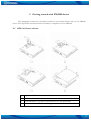
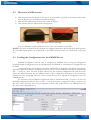
2.1 SIM card insert scheme
Open the SIM holder and insert the SIM card as shown.
Close the SIM holder
Push SIM holder’s top part in shown direction to clip SIM holder
Assemble device with enclosure’s top part as shown and screw the bolts.
3
2.2 Installing FM2200 drivers
In order to configure FM2200, “MS Windows XP Service Pack 2” or later version of MS
Windows must be installed.
64 bit systems are not supported
Please note that FM22 drivers support only 32bit operating systems.
“MS Windows XP SP2”
Before connecting FM2200 to the computer, the special Hot Fixes must be installed:
1) Hotfix KB918365 (usbser.sys 5.1.2600.2930);
2) Hotfix KB935892 (usbccgp.sys 5.1.2600.3116).
After installing the HotFixes, reboot your PC.
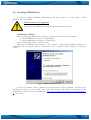
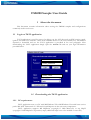
Power up the FM2200 and connect it to the computer. “Found New Hardware Wizard” for
“FM22XX Port” will appear. Choose “Install from a list or specific location” (Figure 1) and press
“Next”.
Figure 1. FM2200 installation step 1
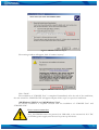
In the new window, choose “Search for the best driver in these locations” and check the
“Include this location in the search” box. Then click browse and specify the location of the
“FM22XX.inf” file, it can be downloaded from http://avl1.teltonika.lt/Downloads/FM22/FM22XX.zi
p. Click “Next”.
4
Figure 2. FM2200 installation step 2
The warning window will appear, click “Continue Anyway”.
Figure 3. FM2200 installation step 3
Click “Finish”.
The installation of “FM22XX Port” is completed. Immediately after the end of the installation,
the new wizard for “FM22XX GPS” will appear. Repeat all the steps as in previous installation.
“MS Windows XP SP3” and “MS Windows Vista”
No HotFix installation is required. Proceed with the installation of “FM22XX Port” and
“FM22XX GPS”.
Power source connection
Note, that FM2200 cannot be powered via USB cable, so the external 10...30 V DC
(12 W Max) power supply must be used to power up the device.
5
2.3
Placement of GPS antenna
•
•
•
GPS antenna must be placed so its state is as horizontal as possible (if antenna is leant more
than 30 degrees, it is considered incorrect mounting).
GPS antenna cable cannot be bent more than 80 degrees.
GPS antenna must be placed sticker facing down
Pic. 1. GPS antenna correct mounting
It is recommended to place GPS antenna as close to the window as possible.
NOTE, that most of modern house windows are equipped with filters that could block GPS signal so
for best GPS signal quality we recommend to put GPS antenna outside (on windowsill, some plate
etc.).
2.4 Loading the Configuration into the FM2200 Device
FM2200 Configurator must be used to configure the FM2200 device. Using the configurator
prepared Sample Configurations can be uploaded into the FM2200 or custom device configuration can
be made.
Configuration files for all Sample Scenarios (described in 3 paragraph) are allready prepared by
Teltonika. Open the FM2200 Configurator software, select correct COM port and click on “Load from
File…” button (1) from the main toolbar. Browse for the required configuration file and click OK.
Enter the APN parameters into the GPRS section of the configuration according to the instructions
described in 2.4.1 paragraph. Click on “Save to Flash” button (2) to upload the configuration into the
FM2200 device.
To check the current FM2200 configuration click on “Read from Flash” (3) button. To save the
modified configuration click on “Save to File…” button (4) and the configuration will be saved into the
file with “.xml” extension. The saved configuration will be able to upload into any FM2200 device in
the same way as described above.
6
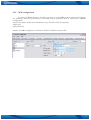
2.4.1 APN configuration
In order to FM2200 device to be able to connect to local GPRS network (and send AVL data)
the following APN data (provided by local GSM services provider) must be entered into FM2200
configuration:
Acces Point Name (APN) with authentication type CHAP or PAP (if required);
APN login;
APN password;
Sample of GPRS configuration of German “EPLUS” GSM service provider:
7
3 Sample scenarios
This section of the document describes the commonly used FM2200 testing scenarios and helps
users to perform the detailed testing of the FM2200 device. Below you will find the descriptions of the
sample scenarios and the configuration for each case.
3.1 First test
Usually the client’s office is the first environment, in which the FM2200 device is tested at the
beginning. To make this test faster the sample FM2200 devices are shipped being equipped with
prepared configuration. You can also use “1stScenarioConfig.xml” file to upload the device with the
prepared configuration.
3.1.1 Configuration
The sample FM2200 devices are shipped already uploaded with “First test” scenario
configuration. The only additional configuration must be made is the APN configuration. The
description of the APN configuration is described in paragraph 2.4.1.
The “First test” scenario configuration is based on fast periodic AVL data acquisition
(Min.period = 30 s) and AVL data sending via GPRS to the server as soon as the AVL data record is
generated (Min. saved records = 1; Send period = 1 s). According to this configuration one AVL data
record, containing information about the GPS position and Input/Output (I/O) parameters is sent to
the server every 30 seconds.
Following I/O elements’ vales are monitored in every AVL data record:
• DIN1 (as ignition) {values: 0 – Off; 1 – On};
• Movement {values: 0 – object is not moving; 1 – object is moving};
• Power voltage {values: from 10 V to 30 V, according to the power source).
3.1.2 What is the purpose of testing FM2200 in this scenario?
After the testing is successfully done, the user is introduced to the basic FM2200 work - periodic
AVL data acquisition and sending to the server with monitoring of the basic I/O parameters. The user
is able to see his position according to GPS in the TAVL application software.
8
3.2 City Scenario
One of the most widely used scenarios of the FM2200 testing scenario is testing the device in the
“City Scenario”.
3.2.1 Configuration
To completely test the “City Scenario” please load the prepared configuration file
“2ndScenarioConfig.xml” which has been received together with this document. Follow the
instructions in paragraph 2.4 to upload the FM2200 with the required configuration.
Again the only additional configuration must be made is the APN configuration. The
description of the APN configuration is described in paragraph 2.4.1.
The “City” scenario configuration is based on fast periodic AVL data acquisition mainly
according to the change of the object’s geographic angle (Min.Angle = 20 degrees). According to this
configuration the FM2200 device will generate AVL record every time the object’s angle is changed
more than 20 degrees. Such AVL data acquisition is rational in cases the object mostly moves in the
city. Min.Distance = 200 meters, so the additional AVL record will be generated after driving more
than 200 meters in the straight line. If the object with FM2200 device is not moving, the AVL data
records are generated periodically every 600 seconds (Min.period = 600 s).
AVL data is sent via GPRS to the server as soon as the AVL data record is generated (Min.
saved records = 1; Send period = 1 s). According to this configuration one AVL data record,
containing information about the GPS position and Input/Output (I/O) parameters is sent to the
server at least every 600 seconds.
Following I/O elements’ vales are monitored in every AVL data record:
• DIN1 (as ignition) {values: 0 – Off; 1 – On};
• Movement {values: 0 – object is not moving; 1 – object is moving};
• Power voltage {values: from 10 V to 30 V, according to the power source).
• Speed {values: current vehicle speed in km/h}
Additional AVl data records called “events” are generated on following parameter value
changes:
• If power voltage value falls to less than 11 V;
• Speed is less than 5 km/h for more than 1 minute;
• Ignition is turned ON/OFF (DIN1=1 or DIN1=0).
3.2.2 What is the purpose of testing FM2200 in this scenario?
The main propose of this testing scenario is for the user to see the highly detailed track (as in
the sample screenshot below) of his driven track in the city. The user will be able to see his vehicles
current position as well as the position in any selected time in the past. The user will be able to see the
time and points in the map in which the ignition has been turned ON/OFF, power voltage has become
less then 11 V (car battery needs to be recharged).
9
Pic. 2. Track of the FM2200 working in "City scenario"
The track showed in the screenshot above contains the information of 3 days driving of real vehicle in
the city of Vilnius, Lithuania. Using the service of local GSM service provider “Bite GSM” 1 MB of
data has been transmitted through the GPRS to generate such track.
NOTE, that GPRS traffic differs from the GPRS coverage at the area and the GSM
service provider’s data averaging policy, so the GPRS traffic can be higher than the
described in the example above.
3.3 Event based “Logbook” scenario
Another useful FM2200 testing scenario is testing the device in the “Logbook” scenario. Working
in such scenario the position of the object with FM2200 device and I/O elements’ values are sent to
the server via GPRS on high priority events – when I/O elements’ values exceeds the configured
thresholds.
10
3.3.1 Configuration
To completely test the event based “Logbook” scenario please load the prepared configuration
file “3rdScenarioEventBased.xml” which was received together with this document.
Again the only additional configuration must be made is the APN configuration. The
description of the APN configuration is described in paragraph 2.4.1.
The “Logbook” scenario configuration is based on rare periodic AVL data acquisition
(Min.period = 1 hour). According to this configuration the FM2200 device will generate AVL record
every one hour and if any of the below described I/O elements’ values are increased or decreased over
the configured thresholds.
Periodic AVL data is sent via GPRS to the server once a day (Min. saved records = 24; Send
period = 300 s) if no I/O event happen. If any of the events described below happen, the AVL data
record with all AVL information is sent to the server as soon as the event appears.
Following I/O elements’ vales are monitored in every AVL data record:
• DIN1 (as ignition) {values: 0 – Off; 1 – On};
• DIN2 (as panic button) {values: 0; 1);
• Power voltage {values: from 10 V to 30 V, according to the power source);
Additional AVl data records called “events” are generated on following parameter value
changes:
• If power voltage value falls to less than 11 V;
• Speed is less than 5 km/h for more than 1 minute;
• Ignition is turned ON/OFF (DIN1=1 or DIN1=0);
• Panic button is pressed (DIN2 = 1).
3.3.2 What is the purpose of testing FM2200 in this scenario?
After the testing is successfully done, the user is introduced to the FM2200 work based on events.
Such device’s functionality is needed in cases when no detailed track is needed but the work of any
vehicle is needed to be monitored. The user will be able to see the information about the exact time of
turning the ignition On or OFF, Panic Button activation, vehicles battery voltage decrease. Such event
based Logbook is usually needed for the companies administrating big amount of the working vehicles.
Driver’s and vehicle’s working hours can be monitored using such case.
Note, that if any additional information about the configuration or working of the FM2200 device is
needed, please see the latest „FM2200 User Manual“.
11