1
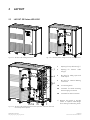
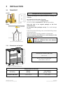
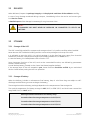
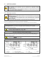
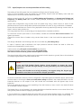
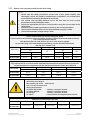
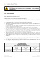
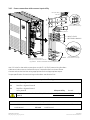
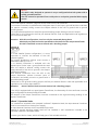
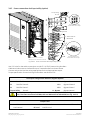
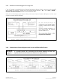
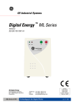
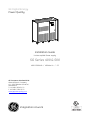
GE Digital Energy
Power Quality
GE_01
0_S2_UPS_
SGS_400-50
Installation Guide
Uninterruptible Power supply
SG Series 400 & 500
400 & 500 kVA / 480Vac UL / S2
GE Consumer & Industrial SA
General Electric Company
CH – 6595 Riazzino (Locarno)
Switzerland
T +41 (0)91 / 850 51 51
F +41 (0)91 / 850 52 52
www.gepowerquality.com
imagination at work
Model:
SG Series 400 & 500 UL S2
Issued by
Product Document Department – Riazzino - CH
Date of issue:
06/15/2010
File name:
OPM_SGT_ISG_M40_M50_2US_V010
Revision:
1.0
Identification No.:
Up-dating
Revision
Concerns
Date
COPYRIGHT © 2010 by GE Consumer & Industrial SA
All rights reserved.
The information contained in this publication is intended solely for the purposes indicated.
The present publication and any other documentation supplied with the UPS system is not to be
reproduced, either in part or in its entirety, without the prior written consent of GE.
The illustrations and plans describing the equipment are intended as general reference only and are not
necessarily complete in every detail.
The content of this publication may be subject to modification without prior notice.
Modifications reserved
OPM_SGS_ISG_M40_M50_2US_V010.doc
Page 2/41
User Manual SG Series 400 & 500 UL S2
Dear Customer,
We thank you for selecting our products and are
pleased to count you amongst our very valued
customers at GE.
We trust that the use of the SG Series 400 & 500
Uninterruptible Power Supply system, developed and
produced to the highest standards of quality, will give
you complete satisfaction.
Please read carefully the Installation Guide, which
contains all the necessary information and describes all
you need to know about the installation of the UPS.
Thank you for choosing GE !
START UP AND COMMISSIONING
A GE GLOBAL SERVICES FIELD ENGINEER must perform start-up and
commissioning of the UPS.
Please Contact GE. GLOBAL SERVICES at least two weeks prior to schedule
start-up and commissioning at 1-800-637-1738, or by E-mail at
[email protected] .
Distributed in the USA by:
g
GE Consumer & Industrial SA
General Electric Company
CH – 6595 Riazzino (Locarno)
Switzerland
www.gepowerquality.com
Your service contact:
g
GE Digital Energy
Power Quality
2501 Pecan Street
Bonham, TX 75418
T: +1 800-637-1738
F: +1 903-640-0533
E: [email protected]
http://www.gedigitalenergy.com/ups
Modifications reserved
OPM_SGS_ISG_M40_M50_2US_V010.doc
Page 3/41
User Manual SG Series 400 & 500 UL S2
Preface
Congratulations on your choice of a SG Series Uninterruptible Power Supply (UPS).
It will help eliminate load disturbances due to unexpected power problem.
This manual describes how to prepare the installation site, and it provides weight and
dimensions and procedures for moving, installing and connecting the UPS.
Please refer to the Operating Manual, which describes the function of the UPS module, the
purpose and location of the switches, the meaning of the system events related to the
front panel indication, and provides procedures for starting and stopping the equipment.
While every care has been taken to ensure the completeness and accuracy of this manual,
GE assumes no responsibility or liability for any losses or damages resulting from the use
of the information contained in this document.
WARNING!
SG Series 400 & 500 is a product that needs to be installed by a licensed and
knowledgeable contractor.
We recommend that this manual be kept next to the UPS for future references.
If any problems are encountered with the procedures contained in this manual, please
contact your Service Center before you proceed.
This document shall not be copied or reproduced without the permission of GE.
Some of the information contained in this manual may be changed without notice to
reflect technical improvements.
Safety instructions
Read the safety instructions contained on the following pages carefully before the
installation of the UPS, options and battery system.
Pay attention to the rectangular boxes included in the text:
They contain important information and warning concerning electrical connections and
personnel safety.
Parallel version secured with RPA
When included in the text, this symbol refers to operation needed
only for parallel system.
Modifications reserved
OPM_SGS_ISG_M40_M50_2US_V010.doc
Page 4/41
User Manual SG Series 400 & 500 UL S2
Table of contents
Page
1
IMPORTANT SAFETY INSTRUCTIONS ........................................................................................................ 6
2
LAYOUT.......................................................................................................................................................... 9
2.1
3
LAYOUT SG Series 400 & 500 .......................................................................................................................................................9
INSTALLATION............................................................................................................................................ 10
3.1
TRANSPORT....................................................................................................................................................................................... 10
3.1.1
3.2
3.3
3.3.1
3.3.2
3.4
Power wiring of parallel units..................................................................................................................................................... 32
Parallel control bus connection................................................................................................................................................. 33
Control bus cable location ........................................................................................................................................................... 35
CUSTOMER INTERFACE ............................................................................................................................. 37
4.1
CUSTOMER INTERFACE ................................................................................................................................................................ 37
4.1.1
4.1.2
4.1.3
4.1.4
4.1.5
4.1.6
4.1.7
5
Power connections.......................................................................................................................................................................... 22
Power connection with common input utility..................................................................................................................... 24
Power connection dual input utility (option)........................................................................................................................ 26
Battery and External Battery Breaker connection ........................................................................................................... 29
Interface to External Bypass for single unit......................................................................................................................... 30
Connections to External Bypass switch in case of RPA Parallel System ................................................................ 30
Setup for SG Series 400 & 500 intended to be operated in eBoost™ Operation Mode.................................... 31
RPA PARALLEL SYSTEM CONNECTION .................................................................................................................................. 32
3.9.1
3.9.2
3.9.3
4
Utility input connection................................................................................................................................................................. 18
Input/output over current protection and wire sizing..................................................................................................... 19
Battery over current protection and wire sizing................................................................................................................ 20
WIRING CONNECTION.................................................................................................................................................................. 22
3.8.1
3.8.2
3.8.3
3.8.4
3.8.5
3.8.6
3.8.7
3.9
UPS location ....................................................................................................................................................................................... 12
Battery location ................................................................................................................................................................................ 14
VENTILATION AND COOLING..................................................................................................................................................... 15
UNPACKING ...................................................................................................................................................................................... 16
ELECTRICAL WIRING...................................................................................................................................................................... 18
3.7.1
3.7.2
3.7.3
3.8
Storage of the UPS .......................................................................................................................................................................... 11
Storage of battery ........................................................................................................................................................................... 11
PLACE OF INSTALLATION ............................................................................................................................................................ 12
3.4.1
3.4.2
3.5
3.6
3.7
Dimensions and weight................................................................................................................................................................. 10
DELIVERY ............................................................................................................................................................................................ 11
STORAGE ............................................................................................................................................................................................ 11
Serial Port J3 ...................................................................................................................................................................................... 38
Output free potential contacts .................................................................................................................................................. 38
Programmable input free contacts ......................................................................................................................................... 39
Gen Set Signaling (GEN ON)......................................................................................................................................................... 39
AUX external Maintenance Bypass ......................................................................................................................................... 39
Auxiliary Power Supply (APS) 24Vdc and Battery Breaker Release........................................................................... 39
EPO (Emergency Power Off) Input contact........................................................................................................................... 40
NOTES .......................................................................................................................................................... 41
5.1
NOTES FORM .................................................................................................................................................................................... 41
Modifications reserved
OPM_SGS_ISG_M40_M50_2US_V010.doc
Page 5/41
User Manual SG Series 400 & 500 UL S2
1
IMPORTANT SAFETY INSTRUCTIONS
SAVE THESE INSTRUCTIONS
This manual contains important instructions for models SG Series 400 & 500 that should be followed
during installation and maintenance of the UPS and battery.
GENERAL
-
Move the UPS in an upright position in its original package to the final destination room.
To lift the cabinets, use a forklift or lifting belts with spreader bars.
Check for sufficient floor and elevator loading capacity.
Check the integrity of the UPS equipment carefully.
If you notice visible damage, do not install or start the UPS.
Contact the nearest Service Center immediately.
WARNING! RISK OF ELECTRICAL SHOCK:
Do not remove covers, there are no user serviceable parts inside.
After switching off takes 5 minutes for the DC capacitors to discharge because a lethally high voltage
remains at the terminals of the electrolytic capacitors.
All maintenance and service work should be performed by qualified service personnel.
The UPS contains its own energy source (battery).
The field-wiring outlets may be electrically live, even when the UPS is disconnected from the utility.
Dangerous voltages may be present during battery operation.
The battery must be disconnected during maintenance or service work.
This UPS contains potentially hazardous voltages.
Be aware that the inverter can restart automatically after the utility voltage is restored.
INSTALLATION
-
This UPS must be installed and connected only by trained personnel.
Verify accurately during Commissioning and Maintenance of the UPS, for the following:
Damaged components, squeezed wires and cables, or not correctly inserted plugs.
After removing the sidewalls of the UPS, make sure that all earth connections when reassembling, are
correctly reattached.
This UPS is intended for use in a controlled indoor environment free of conductive contaminants and
protected against animals intrusion.
WARNING! HIGH EARTH LEAKAGE CURRENT:
Earth connection is essential before connecting to AC input!
Switching OFF the unit does not isolate the UPS from the utility.
Do not install the UPS in an excessively humid environment or near water.
Avoid spilling liquids on or dropping any foreign object into the UPS.
The unit must be placed in a sufficiently ventilated area; the ambient temperature should not exceed 104°F (40°C).
Optimal battery life is obtained if the ambient temperature does not exceed 77°F (25°C).
It is important that air can move freely around and through the unit. Do not block the air vents.
Avoid locations in direct sunlight or near heat sources.
STORAGE
-
Store the UPS in a dry location; storage temperature must be within -13°F (-25°C) to 131°F (+55°C).
The optimal temperature for Battery storage is 68°F (20°C) to 77°F (25°C) and shall never exceed the range 4°F (-20°C) to 104°F (40°C).
If the unit is stored for a period exceeding 3 months, the battery must be recharged periodically (time
depending on storage temperature).
BATTERY
-
The battery-voltage is dangerous for person’s safety.
When replacing the battery, use the same cells number, voltage (V), capacity (Ah).
All the battery used, shall be of the same manufacturer and date of production.
Proper disposal or recycling of the battery is required.
Refer to your local codes for disposal requirements.
Never dispose of battery in a fire: they may explode.
Do not open or mutilate battery: their contents (electrolyte) may be extremely toxic.
If exposed to electrolyte, wash immediately with plenty of water.
Avoid charging in a sealed container.
Never short-circuit the batteries.
When working with batteries, remove watches, rings or other metal objects, and only use insulated tools.
In case of air shipment, the cables +/- going to the battery fuses/terminals shall be disconnected and isolated.
Modifications reserved
OPM_SGS_ISG_M40_M50_2US_V010.doc
Page 6/41
User Manual SG Series 400 & 500 UL S2
Safety instructions when working with battery
EXTERNAL BATTERY MUST BE INSTALLED AND CONNECTED TO THE UPS BY
QUALIFIED SERVICE PERSONNEL ONLY.
INSTALLATION PERSONNEL MUST READ THIS ENTIRE SECTION BEFORE HANDLING
THE UPS AND BATTERY.
DANGER!
Full voltage and current are always present at the battery terminals.
The battery used in this system can provide dangerous voltages, extremely high currents and a
risk of electric shock.
If the terminals are shorted together or to ground they may cause severe injury.
You must be extremely careful to avoid electric shock and burns caused by contacting battery
terminals or shorting terminals during battery installation.
Do not touch uninsulated battery terminals.
A qualified service person, who is familiar with battery systems and required precautions, must
install and service the battery.
The installation must conform to national and local codes.
Keep unauthorized personnel away from the battery.
The qualified service person must take these precautions:
1 Wear protective clothing, such as rubber gloves and boots and protective eye wear
Batteries contain caustic acids and toxic materials and can rupture or leak if mistreated.
Remove rings and metal wristwatches or other metal objects and jewelry.
Do not carry metal objects in your pockets where the objects can fall into the battery
cabinet.
2 Tools must have insulated handles and must be insulated so that they will not short battery
terminals.
Do not allow a tool to short between individual or separate battery terminals or to the
cabinet or rack.
Do not lay tools or metal parts on top of the battery, and do not lay them where they could
fall onto the battery or into the cabinet.
3 Install the battery as shown on the drawing provided with the battery.
When connecting cables, never allow a cable to short across a battery’s terminals, the
string of battery, or to the cabinet or rack.
4 Align the cables on the battery terminals so that the cable lug will not contact any part of
the cabinet or rack, even if the battery is moved.
Keep the cable away from any sharp metal edges.
5 Install the battery cables in such a way that the UPS or battery cabinet doors cannot pinch them.
6 Do not connect the battery terminal to Ground.
If any battery terminal is inadvertently grounded, remove the source of the ground.
Contacting any part of a grounded battery can cause a risk of electric shock.
7 To reduce the risk of fire or electric shock, install the battery in a temperature and humidity
controlled indoor area, free of contaminants.
8 Battery system chassis ground (earth) must be connected to the UPS chassis ground (earth).
If you use conduits, this ground conductor must be routed in the same conduit as the
battery conductors.
9 Where conductors may be exposed to physical damage, protect the conductors in
accordance with all applicable codes.
10 If you are replacing the battery or repairing battery connections, shut OFF the UPS and
remove the battery fuses.
Modifications reserved
OPM_SGS_ISG_M40_M50_2US_V010.doc
Page 7/41
User Manual SG Series 400 & 500 UL S2
Safety symbols and warnings
Safety warnings
The text of this manual contains some warnings to avoid risk to the persons and to avoid damages to
the UPS system and the supplied critical loads.
The non-observance of the warnings reminding hazardous situations could result in human injury and
equipment damages.
Please pay attention to the meaning of the following warnings and symbols.
Throughout this manual the following symbols are defined:
WARNING, if instruction is not followed injury or serious equipment damage may
occur!
CAUTION, internal parts have dangerous voltage present.
Risk of electric shock!
PE (Earth) – GND (Ground)
PROTECTIVE GROUNDING TERMINAL:
A terminal which must be connected to earth ground prior to making any other
connection to the equipment.
A terminal to which or from which an alternating (sine wave) current or voltage
may be applied or supplied.
A terminal to which or from which a direct current or voltage may be applied or
supplied.
This symbol indicated the word “phase”.
This symbol indicates the principal on/off switch in the on position.
This symbol indicates the principal on/off switch in the off position.
Modifications reserved
OPM_SGS_ISG_M40_M50_2US_V010.doc
Page 8/41
User Manual SG Series 400 & 500 UL S2
2
LAYOUT
2.1
LAYOUT SG Series 400 & 500
SGS_400-5
00_S2_UP
SGSU_400-
S_GE_02
0 OFF
0 OFF
I ON
Q2
1 2
3 4 5
6 7 8
12 13
9 10
14 15 16
11
17 18
19 20 21
22
S_03
I ON
Q1
500_S2_UP
12
1 2
3 4
5 6 7
12 13 14
8 9
15 16
10 11
17 18 19
20 21
22
Fig. 2.1-1 SG Series 400 & 500 general view
Fig. 2.1-2 SG Series 400 & 500 general view with open doors
SGSU_400
-500_S2_
UPS_04
1
4
1
Opening for top cable entry (*)
2
Opening
entry(*)
3
Bus bars for Utility input and
Load output
4
Bus bars for external Battery
connection
CR
Connectivity Rack
XA
Terminals for 24Vdc Auxiliary
Power Supply connection
XB
Terminals for EPO connection
3
0 OFF
cable
I ON
Q2
0 OFF
I ON
Q1
for bottom
1 2 3
4 5 6 7
12 13 1 4
8 9 21
15 16 17
22
18 1 9
2 0 10 11
*) Remove this panel or provide
XA/XB CR
2
means to capture metal filings
from cutting conduit entry holes.
Fig. 2.1-3 SG Series 400 & 500 general view with optional 5th harmonic filter and
removed protection panels
Modifications reserved
OPM_SGS_ISG_M40_M50_2US_V010.doc
Page 9/41
User Manual SG Series 400 & 500 UL S2
3
INSTALLATION
3.1
TRANSPORT
Forklift
Transport UPS only in upright position!
The UPS is packaged on a pallet suitable for handling with
a forklift.
Pay attention to the center of gravity.
The UPS must be moved in upright position.
Do not tilt cabinets more than +/- 10° during handling.
Move the UPS in it’s original package to the final
destination site.
Crane
Do not stack other packages on top: This could damage
the UPS.
If the UPS must be lifted by crane, use suitable lifting straps
and spreader bars.
Note of the center of gravity marked on the package.
Take all necessary precautions to avoid damage to the
cabinet while hoisting the UPS.
NOTE !
Check for sufficient floor and elevator
loading capacity.
Fig. 3.1-1 UPS cabinets moving
3.1.1 Dimensions and weight
UPS
-500_S2_
SGSU_400
US
ns_GE_01
dimensio
Dimensions SG Series 400 & 500
(W x D x H)
H
80.71 x 33.47 x 76.78 inches
2,050 x 850 x 1,950 mm
W
D
Fig. 3.1.1-1 UPS cabinet dimensions
Weight SG Series 400 & 500
UPS rating
Weight
lbs / kg
Floor loading
lbs/sq.ft - kg/m2
SG Series 400 & 500
5,226 / 2,370
279 / 1,359
P.S.: Weights including the 5th harmonic filter.
Modifications reserved
OPM_SGS_ISG_M40_M50_2US_V010.doc
Page 10/41
User Manual SG Series 400 & 500 UL S2
3.2
DELIVERY
When delivered, inspect the package integrity and the physical conditions of the cabinets carefully.
In case of any damage sustained during transport, immediately inform the carrier and contact your
local Service Center.
A detailed report of the damage is necessary for any insurance claim.
NOTE !
A DAMAGED UPS MUST NEVER BE INSTALLED OR CONNECTED TO UTILITY OR
BATTERY!
3.3
STORAGE
3.3.1 Storage of the UPS
The UPS is carefully packed for transport and storage so that it is in perfect condition when installed.
Never leave a UPS outside the building and don’t store other packages on the top of the UPS.
It is advisable to store the UPS in its original package in a dry, dust-free room, away from chemical
substances, and with a temperature range not exceeding -13°F (-25°C) to 131°F (55°C).
In case the battery is included please refer to Section 3.3.2.
Some important functions of the UPS, such as the customized functions, are defined by parameters
stored in a RAM memory.
A small backup battery located on the Control Unit board supplies the RAM.
If the storage time of the UPS exceeds 1 year, these functions should be verified by an authorized
Service Center before putting the UPS into operation.
3.3.2 Storage of battery
When the delivery includes a maintenance free battery, keep in mind that they are subject to selfdischarge and therefore you must recharge the battery.
The storage time without battery recharge depends on the temperature of the storage site.
The optimal temperature for Battery storage is 68°F (20°C) to 77°F (25°C) and shall never exceed the
range -4°F (-20°C) to 104°F (40°C).
Recharge stored maintenance free battery every:
6 months when the storage temperature is 68°F (20°C)
3 months when the storage temperature is 86°F (30°C)
2 months when the storage temperature is 95°F (35°C)
Modifications reserved
OPM_SGS_ISG_M40_M50_2US_V010.doc
Page 11/41
User Manual SG Series 400 & 500 UL S2
3.4
PLACE OF INSTALLATION
3.4.1 UPS location
WARNING !
A QUALIFIED ELECTRICAL CONTRACTOR must carry out the installation and cabling
of the UPS.
If optional cabinets and accessories are included with the UPS, please refer to those
accompanying manuals for installation and operating instructions.
It is important to have a clean, dust-free environment provided with proper ventilation and airconditioning to keep the ambient temperature within the specified operating range.
The recommended air inlet temperature is from 68°F (20°C) to 77°F (25°C) (max. 104°F / 40°C).
Refer to Section 3.5.
Check for sufficient floor load capacity before installing the UPS and the Battery.
Refer to Section 3.1.1.
For Battery installation follow the local codes and the recommendation of the battery supplier.
NOTE !
Temperature is very important for valve-regulated batteries (maintenance free).
Operation at temperatures higher than 77°F (25°C) will reduce battery life.
The SG Series 400 & 500 UPS can radiate radio frequency energy.
Although some RFI filtering is inherent to the UPS there is no guarantee that the UPS will not influence
sensitive devices such as cameras and monitors that are positioned close by.
If interference is expected, the UPS should be moved away from the sensitive equipment.
A single-phase power outlet (120Vac) should be provided near the UPS for connection of power tools,
test equipment or connectivity devices. This outlet must be grounded.
Positioning of the UPS SG Series 400 & 500
Min.
20" / 500mm
on_01
PS dispositi
00_S2_U
SGSU_400-5
The rear panel of the UPS may be mounted flush
to a wall or other structure.
Clearance around the front of the unit should be
sufficient to enable free passage of personnel with
the doors fully open, and to allow sufficient airflow
to the door vents.
Check section 110-26(A) of the NEC code for
specific requirements.
Recommended minimum clearance between
ceiling and top of the UPS should be 20” (500 mm)
for proper cooling air exhaust.
In case of additional cabinets (external Batteries or
input, output transformers) these can be placed on
either side of the cabinet.
Fig. 3.4.1-1 SG Series 400 & 500 clearances
Modifications reserved
OPM_SGS_ISG_M40_M50_2US_V010.doc
Page 12/41
User Manual SG Series 400 & 500 UL S2
Openings for input and output cable connections
U_4
SGS
00-5
00_S
PS
2_U
Utility input
Output Load
Battery
US
_01
top
view
80.71"
2,050mm
7.88"
200mm
1.58"
40mm
7"
1.9 mm
50
3"
29.5 mm .47"
33 mm
7 50
850
Fig. 3.4.1-2 Opening on top of the cabinet for input and output cables
vie
UPS
S2 _
00_
00-5
U_4
SGS
m
otto
wb
Utility input
Output Load
Battery
80.71"
2,050mm
US
_01
7.88"
200mm
5"
3.1 m
80m
1.19"
30mm
6"
27.5 mm 7"
700 33.4mm
850
SG Series 400 & 500
openings are provided
on the top and the
bottom of the UPS for
the connection of input
and output cables.
Pay attention to the
position
of
these
openings,
when
choosing
the
placement of the UPS.
These openings are
covered
with
a
protective plate.
Fig. 3.4.1-3 Opening on the bottom of the cabinet for input and output cables
Fixing of the UPS cabinet on the floor
The UPS cabinet is free standing and normally does not require to be bolted to the floor.
The UPS cabinet can be fixed however to the floor by bolting it with the supporting blocks to the
floor. See Fig. 3.4.1-4.
62.205"
1580mm
22.658"
575.5mm
22.028"
559.5mm
33.268"
845mm
28.740"
730mm
=
30.040"
763mm
=
Ø 0.47305"
Ø 12mm
1.378"
35mm
2.363"
60mm
1.378"
35mm
2.363"
60mm
SGSU_400-500_S2_UPS view bottom_02US
Front side
Fig. 3.4.1-4 Fixing of the UPS cabinet on the floor
Modifications reserved
OPM_SGS_ISG_M40_M50_2US_V010.doc
Page 13/41
User Manual SG Series 400 & 500 UL S2
A
500_S2_RP
SGSU_400-
disposition
_GE_01US
UPS
3-4-5-6
UPS 2
UPS 1
Fig. 3.4.1-5 RPA system disposition
In case of parallel system, try to place the UPS modules in sequence of their numbers (marked on
the packing).
If the units are positioned “side by side”, the side panels must be mounted on all units.
3.4.2 Battery location
Batteries require a well-ventilated room with controlled temperature to obtain reliable operation.
The battery can be install immediately adjacent to the UPS (left or right side) or remotely from the UPS.
If the battery is installed remotely from the UPS, a wall mounted DC disconnect device must be installed
within line-of-site to both the UPS and the battery.
The optimal room temperature for Battery storage is 68°F (20°C) to 77°F (25°C) and shall never exceed
the range -4°F (-20°C) to 104°F (40°C).
The life of valve-regulated batteries will be reduced by 50% for each additional 18°F (10°C) that the
battery ambient temperature is above 77°F (25°C).
The battery system associated with larger UPS is usually either rack mounted or installed in multiple
battery cabinets.
Installation and assembly must be made according to the local standards and battery system
manufacturer‘s recommendations.
The battery circuit breaker or battery fuse box must be mounted as near as possible to the battery.
NOTE !
Battery installation and connection must be performed by QUALIFIED SERVICE
PERSONNEL ONLY.
Read all safety instructions before proceeding with the installation.
Modifications reserved
OPM_SGS_ISG_M40_M50_2US_V010.doc
Page 14/41
User Manual SG Series 400 & 500 UL S2
3.5
VENTILATION AND COOLING
Fig. 3.5-1 Installation on plain floor
Fig. 3.5-2 Installation on raised floor
The heat produced by the UPS is transferred to the environment by its ventilation.
Air inlets for UPS ventilation are located on the front of the UPS, while air outlets are on top of the
cabinet.
A suitable ventilation or cooling system must be installed to extract the heat from the UPS room.
NOTE !
Do not put anything on the top of the cabinet.
Air filtration systems could be required when the UPS operates in a dirty environment.
Contact your Dealer or the nearest Service Center for appropriate solutions.
In order to prevent overheating of the UPS, the available air intake flow rate must exceed the total air
exhaust flow rate requirement of the UPS system.
The below table indicates the heat dissipation at full load at PF = 0.9 lag. and charged battery, up to
3,280 ft (1,000 m) altitude, for cooling air 77°F (25°C) to 86°F (30°C).
Losses
UPS rating with options
Cooling air flow
BTU / hr
kW
CFM
m3 / h
SG Series 400 with 5th filter
78,499
23.0
3,949
6,709
SG Series 400 with 5th & 11th filter
79,864
23.4
4,018
6,825
SG Series 400 in eBoost™ Operation Mode
13,652
4.0
687
1,167
SG Series 500 with 5th filter
99,659
29.2
5,013
8,517
SG Series 500 with 5th & 11th filter
101,366
29.7
5,099
8,663
SG Series 500 in eBoost™ Operation Mode
17,065
5.0
859
1,459
Modifications reserved
OPM_SGS_ISG_M40_M50_2US_V010.doc
Page 15/41
User Manual SG Series 400 & 500 UL S2
3.6
UNPACKING
The UPS and Battery Cabinets may be shipped packaged in carton boxes or in wooden crates (if
requested).
Move the cabinets as close as possible to the final location before removing from the pallet.
If delivered in a wooden crate, remove the cabinet from the pallet with care, because of the heavy
weight of the equipment.
White color
Red color
=
=
without any anomaly
anomaly evidence
The package of the SG Series 400 & 500 is
equipped with ShockWatch (indicator for shock),
and TiltWatch (indicator for overthrow) on the
outside.
Fig. 3.6-1 ShockWatch device
These devices indicate an eventual shock or
overthrow during transport.
Whenever these devices show a possible
anomaly, the UPS shall not be commissioned
before consulting a “Service Center”.
Fig. 3.6-2 TiltWatch device
NOTE !
Take care not to damage the UPS when moving by forklift.
A damaged UPS must never be installed or connected to Utility or Battery!
In case of any damage sustained during the transport, immediately inform the
shipping agent!
A detailed report of the damage is necessary for any indemnity claim.
Modifications reserved
OPM_SGS_ISG_M40_M50_2US_V010.doc
Page 16/41
User Manual SG Series 400 & 500 UL S2
Transport fastening to remove
-500_S2_U
SGSU_400
ing_01
ort fasten
PS transp
Rear side
Fig. 3.6-3 Transport fastening to remove
The chokes fitted in the UPS cabinet are supported both at the chassis.
These supports must be removed before placing the cabinet in the final location.
These supports are yellow and are indicated with an appropriate symbol on the assembly layout
drawing (see Fig. 3.6-1).
For parallel systems, the delivery also includes the bus control cables for interconnecting the UPS modules.
Packing material recycling
GE, in compliance with environment protection, use only environmentally friendly
material.
UPS packing materials must be recycled in compliance with all applicable
regulations.
Modifications reserved
OPM_SGS_ISG_M40_M50_2US_V010.doc
Page 17/41
User Manual SG Series 400 & 500 UL S2
3.7
ELECTRICAL WIRING
WARNING !
UPS installation and connection must be performed by QUALIFIED SERVICE
PERSONNEL ONLY.
It is the responsibility of the installation technician to ensure that all local and
national electric codes are adhered to.
3.7.1 Utility input connection
NOTE !
Ensure that the AC and DC external isolators are OFF and locked out to prevent their
inadvertent operation.
Do not apply power to the equipment prior to the commissioning by a QUALIFIED
SERVICE ENGINEER.
Before any other input connection, connect and check the grounding wire.
The UPS has available input terminations for the Rectifier and Bypass.
The unit may be powered from a common input source or dual input (option) sources if desired.
Common Input Rectifier & Bypass
The same power source is to be used for both Bypass Supply and Rectifier Input (input F3).
Bear in mind that when the Utility Fuses are opened there is a supply failure to the Rectifier as well as
to the Bypass and Manual Bypass.
In this case, the interconnection links BR1, BR2 and BR3 on the input terminals or bus
bars MUST REMAIN CONNECTED. See Fig. 3.8.3-3.
Dual Input Configuration Rectifier & Bypass (option)
The Bypass and Rectifier inputs are to be powered from different Utility supplies (F1 and F2 inputs).
In this case, when the Rectifier Input Fuses are opened, the Bypass and the Manual Bypass are
supplied by the other source.
In this case, REMOVE the interconnection links BR1, BR2 and BR3 on the input
terminals or bus bars. See Fig. 3.8.3-3.
Dual Input Configuration Rectifier & Bypass (option)
Common Input Rectifier & Bypass
Fig. 3.7.1-1 Dual Input Configuration Rectifier & Bypass (option)
Fig. 3.7.1-2 Common Input Rectifier & Bypass
1 = Rectifier
2 = Inverter
Modifications reserved
OPM_SGS_ISG_M40_M50_2US_V010.doc
3 = Automatic Bypass
4 = Manual Bypass Q2 (option)
6 = Load
5 = Utility input
7 = Battery
Page 18/41
User Manual SG Series 400 & 500 UL S2
3.7.2 Input/output over current protection and wire sizing
The cabling of the UPS system has to be sized according to the UPS power rating.
Sizing of circuit breakers, fuses and cables for Input Utility, Output Load and Battery must meet the
requirements of local and national electrical codes.
Before connecting the UPS, verify that the Utility Voltage and Frequency, the Output Load Voltage and
Frequency and Battery Data (cells number, floating voltage, autonomy) are according to the required
specifications.
Output load configuration may be such that one phase may carry a load current at 100% of that
phases maximum current rating while the other two phases run at 0% or any combination in between.
Ensure that the load does not consist of any equipment that may require high starting currents such as
electric motors, laser printers, etc.
This may cause the UPS to occasionally go into Bypass due to overload conditions
To choose the correct input fuses or circuit breaker, consider the available short-circuit current of the
system up-stream.
Choose the correct fuse or breaker using current data shown in the chart and the appropriate NEC
code.
The ratings indicated in the following chart do not consider any line voltage drop.
In case of optional input transformer the input protective devices should be sized to allow the
transformer magnetization inrush current.
Caution when using four-pole circuit breakers as protection.
A potential problem exists for situations with non-linear loads:
The neutral current could be greater than the phase currents.
The three-phase Utility power supply must be symmetrical with respect to ground, due to the existence
of voltage surge protection devices inside the UPS.
NOTE !
If you use ELCB breaker (Earth Limiting Circuit Breaker) to protect the input
connections, consider the high leakage current generated by the noise suppression
capacitors.
If these ELCB breakers are strictly necessary, we suggest using the largest type
suitable for non-linear current and for delayed operations.
To ensure coordination when the UPS is configured for Separate Bypass and Rectifier Inputs, special care
must be taken in choosing the fuse or circuit breaker ratings installed in the output distribution circuits.
Protective devices on the output of the UPS should be coordinated with the Bypass Input circuit
protection.
Due to the relatively low short circuit capability of the UPS inverter, a short circuit in the load will cause
an immediate transfer to Bypass.
The largest fuse or circuit breaker in the output distribution should be rated at no more than 60% of the
rating of the protective device supplying the Bypass line.
If circuit selectivity is required while the load is fed from the inverter (Bypass Utility not available), the
largest fuse or circuit breaker should be rated at no more than 20% of the UPS output current rating.
Modifications reserved
OPM_SGS_ISG_M40_M50_2US_V010.doc
Page 19/41
User Manual SG Series 400 & 500 UL S2
3.7.3 Battery over current protection and wire sizing
NOTE !
•
•
•
•
•
•
Please read the safety precautions at the front of this guide carefully, and
thoroughly review the battery manufacturers installation and maintenance
manual before connecting the batteries to the UPS.
The remote rack mounted batteries are to be used then DC over current
protection must be provided by others.
Choose an appropriate DC fuse or circuit breaker using the current data in the
chart below.
Minimum battery cable requirement is based on the current data below.
The maximum available fault current from the battery supply is: 20kA.
The minimum breaker voltage rating is 540V
The AC values below are current ratings per phase.
These maximum and nominal ratings should be considered when choosing the appropriate AC
over current protection device.
NEC (National Electric Code) Section 210-20 a rules must be applied.
DC current rating is the nominal battery discharge current which the UPS allows.
(See Fig. 3.7.1-1 and 3.7.1.2)
UPS rating
AC Input Rectifier
F1
Nom.
Max.
AC Input Bypass
F2
AC Input
F3
Nom.
Max.
DC Input
F4
SG Series 400
512 A
615 A
481 A
512 A
615 A
702 A
SG Series 500
617 A
708 A
600 A
617 A
708 A
960 A
Size of Branch Circuit Over Current Protection - All Models: - "CAUTION - To reduce the risk of fire,
only connect UPS to a circuit provided with (See below) maximum amperes branch circuit over
current protection in accordance with the NEC (National Electric Code), NSI / NFPA 70
UPS rating
AC Input Rectifier
F1
AC Input Bypass
F2
AC Input
F3
DC Input
F4
SG Series 400
800 A
700 A
800 A
1,000 A
SG Series 500
1,000 A
800 A
1,000 A
1,200 A
WIRING
Wire sizing according to
NEC Section 210-20 (a) Table 310-16
Use 75°C (167°F) copper wire
Wiring requirements:
AC INPUT RECTIFIER:
3-Phase, 3 wire plus Ground
AC INPUT BYPASS:
3-Phase, 4 wire plus Ground
AC OUTPUT:
3-Phase, 4 wire plus Ground
DC INPUT:
2 wire (positive and negative) plus Ground
Maximum recommended cable size
UPS rating
Rectifier Input
Bypass Input
DC Input
AC Output
GND
SG Series 400
SG Series 500
4x500 kcmil
4x500 kcmil
4x600 kcmil
4x500 kcmil
3x500 kcmil
Modifications reserved
OPM_SGS_ISG_M40_M50_2US_V010.doc
Page 20/41
User Manual SG Series 400 & 500 UL S2
NEC SECTION 210-20 (a)
Table 310-16. Allowable Ampacities of Insulated Conductors Rated O Through 2000 Volts, 60°C Trough
90°C (140°F Trough 194°F) Not More than Three Current-Carrying Conductors in Raceway, Cable, or
Earth (Directly Buried), Based on Ambient Temperature of 30°C (86°F).
Temperature Rating of Conductor (See table 310-13)
Size
60°C (140°F)
75°C (167°F)
90°C (194°F)
60°C (140°F)
75°C (167°F)
90°C (194°F)
Types
TW, UF
Types
FEPW, RH, RHW,
THHW, THW,
THWN, XHHW,
USE, ZW
Types
TBS, SA, SIS, FEP,
FEPB, MI, RHH,
RHW-2, THHN,
THHW, THW-2,
THWN-2, USE-2,
XHH, XHHW,
XHHW-2,ZW-2
Types
TW, UF
Types
RH, RHW,
THHW,
THW, THWN,
XHHW, USE
Types
TBS, SA, SIS,
THHN, THHW,
THW-2,
THWN-2, RHH,
RHW-2, USE-2,
XHH, XHHW,
XHHW-2,
ZW-2
AWG
or
kcmil
COPPER
----20
25
30
40
55
70
85
95
110
125
145
165
195
215
240
260
280
320
355
385
400
410
435
455
495
520
545
560
18
16
14
12
10
8
6
4
3
2
1
1/0
2/0
3/0
4/0
250
300
350
400
500
600
700
750
800
900
1000
1250
1500
1750
2000
----20
25
35
50
65
85
100
115
130
150
175
200
230
255
285
310
335
380
420
460
475
490
520
545
590
625
650
665
ALUMINIUM or COPPER-CLAD ALUMINIUM
14
18
25
30
40
55
75
95
110
130
150
170
195
225
260
290
320
350
380
430
475
520
535
555
585
615
665
705
735
750
------20
25
30
40
55
65
75
85
100
115
130
150
170
190
210
225
260
285
310
320
330
355
375
405
435
455
470
------20
30
40
50
65
75
90
100
120
135
155
180
205
230
250
270
310
340
375
385
395
425
445
485
520
545
560
------25
35
45
60
75
85
100
115
135
150
175
205
230
255
280
305
350
385
420
435
450
480
500
545
585
615
630
CORRECTION FACTORS
Ambient
Temp. (°C)
For ambient temperatures other than 30°C (86°F), multiply the allowable ampacities shown above by the appropriate factor
below
21 - 25
26 - 30
31 - 35
36 - 40
41 - 45
46 - 50
51 - 55
1.08
1.00
0.91
0.82
0.71
0.58
0.41
Modifications reserved
OPM_SGS_ISG_M40_M50_2US_V010.doc
1.05
1.00
0.94
0.88
0.82
0.75
0.67
1.04
1.00
0.96
0.91
0.87
0.82
0.76
1.08
1.00
0.91
0.82
0.71
0.58
0.41
1.05
1.00
0.94
0.88
0.82
0.75
0.67
1.04
1.00
0.96
0.91
0.87
0.82
0.76
Page 21/41
User Manual SG Series 400 & 500 UL S2
3.8
WIRING CONNECTION
WARNING!
UPS installation and connection must be performed by QUALIFIED SERVICE
PERSONNEL ONLY.
3.8.1 Power connections
Input/output and DC connections are provided with terminal blocks.
Please refer to chart for torque specifications.
Carefully read the following recommendations before proceeding:
•
Ensure that the AC and DC external isolators are OFF and locked to prevent their inadvertent
operation.
•
Do not close any external isolators prior the commissioning of the equipment.
•
The preferred power cable entry location for installation purposes is from the right side of the UPS,
either top or bottom.
In case of cable entry from the top of the cabinet, remove the cover plate fitted on the roof and
provide for a suitable isolated protection cover.
In case of cable entry from the bottom remove cover plate and perform the same procedure.
•
If the UPS is installed in such a way that the accessibility to the right side panel is reduced, field
wiring connections can be made from the front side by removing the front right side panel
protection cover/panel ( E ) as indicated in Fig. 3.8.1-1 be advised that installation performed from
the front position will give the installer reduced visibility to the terminal lugs.
•
The input/output cables must be connected in clockwise phase rotation for both Bypass and
Rectifier Input Terminals if separate, taking care to avoid risk of short circuit between different poles.
•
The grounding and neutral connection of the electrical system must be in accordance with local
regulations.
•
In case of additional cabinets containing batteries, input/ output transformers, etc, their ground
terminals must be connected to the UPS main ground terminal.
•
Once the power cables have been connected, re-install the internal safety shields and close the
cabinets by re-installing all external panels.
Torque Specifications
Lugs bolted to Buss Blades
Input / Output / Neutral / Battery and GND
UPS rating
BOLT Size
(inches)
BOLT Torque
(Lb-in)
BOLT Torque
(N-m)
SG Series 400 & 500
1/2
428
48
Modifications reserved
OPM_SGS_ISG_M40_M50_2US_V010.doc
Page 22/41
User Manual SG Series 400 & 500 UL S2
CAUTION !
Panel “A, B, C and D” should never be removed or replaced with power applied to the
UPS.
This panel is in close proximity to 480V live buss bars.
Always disconnect the rectifier, bypass, load and battery sources from the UPS
before removing or replacing this panel.
If not serious injury or death could occur!
Access to power wiring terminals for the cable connections.
Top entry cables
SGSU_400
-500_S2_
UPS conn
ection_01
US
!
Please remove the plate
before drilling any holes
B
C
D
Q1
0 OFF
I ON
Q2
0 OFF
I ON
A
Bottom entry cables
!
Please remove the plate
before drilling any holes
Detail of the power wiring terminal for external battery connection
Detail of the power wiring terminal for the AC input/output
1.75"
44.5mm
2"
51mm
2"
51mm
2"
51mm
1.02"
26mm
7"
0.5 mm
14.5
0.98"
1.97" 0.98"
25mm 50mm 25mm
Ø 0.55" / 14mm
7"
0.5 mm
14.5
"
31.5 m
80m
Ø 0.55" / 14mm
1.75"
44.5mm
0.79"
20mm
Fig. 3.8.1-1 Access to the input / output connections
To access input, output and Battery Connections proceed as follows:
• Remove the protection panel “A, B and C”.
•
Remove the UPS side panel “D”.
Modifications reserved
OPM_SGS_ISG_M40_M50_2US_V010.doc
Page 23/41
User Manual SG Series 400 & 500 UL S2
3.8.2 Power connection with common input utility
SGS
_4 0
0-5
00_
S2_
UP S
con
nec
tion
c
om
mo
n _G
E_0
PE
PE Input Utility
PE Load
1US
+
-
PE
Typical installation using
common NEMA two hole lugs
Load Neutral
Utility Neutral
L3-1
L2-1
L1-1
1 - INPUT UTILITY
RECTIFIER & BYPASS
PE
L3
L2
Position of the PE bolt in case the
cable input is from the bottom of the UPS
Load
Typical installation using
common NEMA two hole lugs
L1
Fig. 3.8.2-1 Power connections Common Input Utility
Use 1/2” bolts for the cable connections on INPUT / OUTPUT power wiring Bus Bars.
Cable terminations are to the Rectifier Input / Output Bus Bars as shown above.
Connect wire to the Bus Bars using appropriate tools and appropriate torque.
Torque specification for two hole lugs on Bus Bars: see Section 3.8.1.
Common Input Rectifier / Bypass
L1-1
Rectifier + Bypass Phase A
L2-1
Rectifier + Bypass Phase B
L3-1
Rectifier + Bypass Phase C
N
Utility Neutral
PE Input Utility
Ground
The interconnection bus bars BR1, BR2 and BR3 MUST REMAIN CONNECTED (see Fig.
3.8.3-3).
Output Load
L1
Load Phase A
L2
Load Phase B
N
Load Neutral
PE Load
Load Ground
Modifications reserved
OPM_SGS_ISG_M40_M50_2US_V010.doc
L3
Load Phase C
Page 24/41
User Manual SG Series 400 & 500 UL S2
NOTE !
This UPS is only designed to operate in a wye-configured electrical system with a
solidly grounded neutral.
The UPS cannot be operated from a mid-point or end-point grounded delta supply
source.
If the Load requires a Neutral, a Bypass Source Neutral MUST BE PROVIDED.
If no Neutral Connection is available with the Bypass Input (3-wire input + ground) and the Load does
not require a Neutral, solidly connect the Output Neutral of the UPS to ground with a ground
bonding jumper.
For single module applications install the ground bonding jumper directly at the UPS output.
Cable size for this connection shall be per National Electric Code and applicable local regulations,
but not less then AWG 3/0.
Attention: With this configuration, Load can only be connected phase-phase.
Absolutely no Load Connection permitted to the Neutral of the output transformer.
DO NOT install both a source Neutral and a bonding jumper!
In a RPA Parallel System configuration it is most
important to connect the Neutrals of the UPS
outputs together.
The output distribution cabinet must contain a
Neutral Bus (see Fig .3.8.2-2).
If no Neutral Connection is available with the
Bypass Input (3-wire input + ground) and the Load
does not require a Neutral, solidly connect the
Output Neutral of the UPS to ground in the Output
Distribution Cabinet.
Wire Neutral Conductors from the UPS to the
output distribution cabinet (common point of
connection) and solidly connect to ground with a
Fig. 3.8.2-2 RPA Parallel System
ground bonding jumper.
Cable size for the ground bonding jumper shall be per National Electric Code and applicable local
regulations, but not less then AWG 3/0.
Attention:
DO NOT INSTALL both a source Neutral and a bonding jumper.
If the UPS is equipped with an Input Bypass Transformer, the Secondary of the transformer must be
wye-configured with Neutral Solidly Grounded.
The Neutral of the Output Transformer must be connected to the wye secondary winding of the
Bypass Transformer.
eBoost™ Operation Mode
For installations intended to be operated in eBoost™ Operation Mode, the Input Neutral Conductor
must be connected from the source of supply.
An Input Neutral Conductor MUST be pulled into the UPS.
Neutral to ground bonding jumper shall NOT be installed in UPS installations intended to be
operated in eBoost™ Operation Mode.
Contact your Service Center, which will help you to find valuable solutions.
Modifications reserved
OPM_SGS_ISG_M40_M50_2US_V010.doc
Page 25/41
User Manual SG Series 400 & 500 UL S2
3.8.3 Power connection dual input utility (option)
SGS
_4 0
0-5
00_
S2_
UP
S co
nne
c
tion
sep
ara
te_
GE
PE
PE Input Utility
PE Load
_01
US
PE
+
-
Typical installation using
common NEMA two hole lugs
Load Neutral
Utility Neutral
L3-1
L2-1
1 - INPUT UTILITY
RECTIFIER
L1-1
IN
B Y PUT
PA UT
SS ILI
(op TY
tio
n)
L3-2
L2-2
L1-2
2-
PE
L3
L2
Position of the PE bolt in case the
cable input is from the bottom of the UPS
Load
Typical installation using
common NEMA two hole lugs
L1
Fig. 3.8.3-1 Power connections Dual Input Utility (option)
Use 1/2” bolts for the cable connections on INPUT / OUTPUT power wiring Bus Bars.
Cable terminations are to the Rectifier Input / Output Bus Bars as shown above.
Connect wire to the Bus Bars using appropriate tools and appropriate torque.
Torque specification for two hole lugs on Bus Bars: see Section 3.8.1.
Dual Input Configuration Rectifier / Bypass (option)
L1-1
Rectifier Phase A
L1-2
Bypass Phase A
L2-1
Rectifier Phase B
L2-2
Bypass Phase B
L3-1
Rectifier Phase C
L3-2
Bypass Phase C
N - Bypass
Bypass Neutral
PE Input Utility
Ground
For dual input configurations, a neutral conductor is required from the bypass source
only. The interconnection links BR1, BR2 and BR3 MUST BE REMOVED (see Fig. 3.8.3-3).
Output Load
L1
Load Phase A
L2
Load Phase B
N
Load Neutral
PE Load
Load Ground
Modifications reserved
OPM_SGS_ISG_M40_M50_2US_V010.doc
L3
Load Phase C
Page 26/41
User Manual SG Series 400 & 500 UL S2
NOTE !
This UPS is only designed to operate in a wye-configured electrical system with a
solidly grounded neutral.
The UPS cannot be operated from a mid-point or end-point grounded delta supply
source.
If the Load requires a Neutral, a Bypass Source Neutral MUST BE PROVIDED.
If no Neutral Connection is available with the Bypass Input (3-wire input + ground) and the Load does
not require a Neutral, solidly connect the Output Neutral of the UPS to ground with a ground
bonding jumper.
For single module applications install the ground bonding jumper directly at the UPS output.
Cable size for this connection shall be per National Electric Code and applicable local regulations,
but not less then AWG 3/0.
Attention: With this configuration, Load can only be connected phase-phase.
Absolutely no Load Connection permitted to the Neutral of the output transformer.
DO NOT install both a source Neutral and a bonding jumper!
In a RPA Parallel System configuration it is most
important to connect the Neutrals of the UPS
outputs together.
The output distribution cabinet must contain a
Neutral Bus (see Fig .3.8.3-2).
If no Neutral Connection is available with the
Bypass Input (3-wire input + ground) and the Load
does not require a Neutral, solidly connect the
Output Neutral of the UPS to ground in the Output
Distribution Cabinet.
Wire Neutral Conductors from the UPS to the
output distribution cabinet (common point of
connection) and solidly connect to ground with a
Fig. 3.8.3-2 RPA Parallel System
ground bonding jumper.
Cable size for the ground bonding jumper shall be per National Electric Code and applicable local
regulations, but not less then AWG 3/0.
Attention:
DO NOT INSTALL both a source Neutral and a bonding jumper.
If the UPS is equipped with an Input Bypass Transformer, the Secondary of the transformer must be
wye-configured with Neutral Solidly Grounded.
The Neutral of the Output Transformer must be connected to the wye secondary winding of the
Bypass Transformer.
eBoost™ Operation Mode
For installations intended to be operated in eBoost™ Operation Mode, the Input Neutral Conductor
must be connected from the source of supply.
An Input Neutral Conductor MUST be pulled into the UPS.
Neutral to ground bonding jumper shall NOT be installed in UPS installations intended to be
operated in eBoost™ Operation Mode.
Contact your Service Center, which will help you to find valuable solutions.
Modifications reserved
OPM_SGS_ISG_M40_M50_2US_V010.doc
Page 27/41
User Manual SG Series 400 & 500 UL S2
Notices for installation
SGSU_400
-500_S2_U
PS
BR1-2-3_
GE_01
L3-1
L2-1
L1-1
L3-2
BR3
BR2
L2-2
L1-2
BR1
Fig. 3.8.3-3 AC bus bars BR1, BR2 and BR3
For separate Bypass and Rectifier input configuration (option), the AC Bus Bars BR1, BR2 and BR3
MUST BE REMOVED.
Modifications reserved
OPM_SGS_ISG_M40_M50_2US_V010.doc
Page 28/41
User Manual SG Series 400 & 500 UL S2
3.8.4 Battery and External Battery Breaker connection
S GS
U_4
00-5
00_
S2_
UPS
con
nec
tion
batt
ery
_GE
_01
US
PE
Typical installation using
common NEMA two hole lugs
+
-
PE
Fig. 3.8.4-1 Power connections Battery
Use 1/2” bolts for the cable connections on BATTERY power wiring Bus Bars.
Battery Cable Terminations are to the Positive and Negative Terminals as shown above.
Connect wire to the Bus Bars using appropriate tools and appropriate torque.
Torque specification for two hole lugs on Bus Bars: see Section 3.8.1.
Battery connection
+
Positive pole of the battery
-
Negative pole of the battery
PE
Battery ground
Do not insert the Battery Fuses before the
commissioning!
NOTE !
To meet standards concerning electromagnetic compliance, the connection
between the UPS and external Battery must be done by using a shielded cable or
suitable shielded (steel) conduit!
External Battery Breaker Release
For connection or disconnection of the
Battery an external breaker CB with UVR
is required.
The UVR of the external breaker must be
connected to terminal XA (see Fig. 4.1.6-1).
Fig. 3.8.4-2 External battery breaker connection
The release signal will allow, after the
Rectifier soft-start, the manual closure of
the breaker.
In either case, fuses or breaker, an auxiliary contact must signalize the closure of breaker or fuse
holder to Input channel 1 of the P4 - Customer Interface (see Section 4.1).
Contact must be open with Battery disconnected (Normally Open).
Modifications reserved
OPM_SGS_ISG_M40_M50_2US_V010.doc
Page 29/41
User Manual SG Series 400 & 500 UL S2
3.8.5 Interface to External Bypass for single unit
If the UPS system is equipped with an External Maintenance Bypass Switch, connect the NO (normally
open) voltage free auxiliary contact from the External Bypass Switch to X4 - 1, 2 of P27 – IM0108 Interface for External Bypass inserted in the Connectivity Rack.
When this NO (Normally Open) contact closes, the Inverter Output Contactor K7 opens and the Load
transfer to Inverter will be inhibited.
SG Series 400 & 500 has to be
interfaced to the External Bypass
Auxiliary Contacts (NO) for safety
reasons.
This will prevent contactor K7
from closing when the external
bypass breaker is on.
The connections shown in the
diagram are mandatory.
Fig. 3.8.5-1 Interface to External Bypass for single unit
3.8.6 Connections to External Bypass switch in case of RPA Parallel System
In a parallel system, this connection must be made between each UPS to a
separate AUX contact of the External Maintenance Bypass Switch.
Fig. 3.8.6-1 Connections to External Bypass switch in case of RPA Parallel System
Modifications reserved
OPM_SGS_ISG_M40_M50_2US_V010.doc
Page 30/41
User Manual SG Series 400 & 500 UL S2
3.8.7
Setup for SG Series 400 & 500 intended to be operated in eBoost™ Operation Mode
NOTE !
For systems intended to be operated in eBoost™ Operation Mode, the
installation shall be protected with suitable surge protection devices
(SPDs) on the AC bus feeding the UPSs.
Please contact your Service Center for more information.
When using the “eBoost/IEMi control” function on the programmable user
relays of the customer interface X1/J2 terminals in a Parallel System, a
separate NO (Normally Open) contact must be connected to each individual
unit.
Modifications reserved
OPM_SGS_ISG_M40_M50_2US_V010.doc
Page 31/41
User Manual SG Series 400 & 500 UL S2
3.9
RPA PARALLEL SYSTEM CONNECTION
WARNING !
This operation must be performed by QUALIFIED SERVICE PERSONNEL ONLY before
the initial start-up.
ENSURE THAT THE UPS INSTALLATION IS COMPLETELY POWERED DOWN.
3.9.1 Power wiring of parallel units
To guarantee good Load sharing between the units of a Parallel System, we recommend that the cable
length from the input distribution board (5) to the output distribution board (9) is equal for each unit (a+b
= c+d = e+f = g+h = i+l = m+n). Tolerance: +/- 10%.
The RPA Cable Saver option introduces a bypass inductor in every UPS module, minimizing the influence
of external conductor length on bypass current sharing.
The RPA Cable Saver option extends the cable length tolerance to +/-50% for runs not exceeding 160
feet (49m).
The AC input power of the Bypass must be the same for all units of the parallel system - no phase shift
allowed between units.
NOTE !
It is strongly recommended that no transformers, automatic circuit breakers or
fuses be inserted between the unit’s output and the Load common bus bars.
However, it is recommended that a disconnection or isolation switch be installed in
order to totally isolate a unit if needed.
Verify that power wiring and control wiring are run in separate conduits or cable trays.
UPS input cables must be run in separate conduits from the output cables.
Fig. 3.9.1-1 Power wiring of RPA Parallel System
Modifications reserved
OPM_SGS_ISG_M40_M50_2US_V010.doc
1
2
3
4
5
6
7
8
=
=
=
=
=
=
=
=
9
=
c
2
3
4
5
6
=
=
=
=
=
=
Rectifier
Inverter
Automatic Bypass
Manual Bypass (option)
Input Utility Distribution
Unit Output Load
External Battery fuse or MCB
External Battery
Common bus bar and Output
Load Distribution
UPS Number 1
UPS Number 2
UPS Number 3
UPS Number 4
UPS Number 5
UPS Number 6
Page 32/41
User Manual SG Series 400 & 500 UL S2
3.9.2 Parallel control bus connection
In cases of parallel operation, the communication between the units takes place through the control
bus cables.
Each parallel unit is equipped with an additional board “P13 – RPA Board“ where the connectors J52 (A)
and J62 (B) are located.
A short control cable provided with a ferrite ring core links the parallel board “P13 – RPA Board” with the
parallel bus socket on which must be connected the control bus cables JA and JB on PCB “P34 – Bus
Interface”.
All the parallel units are connected to the same control bus.
This connection allows:
• The microprocessors of each unit to communicate with each other.
• The oscillators of each unit to be locked together.
• The regulation loops to compare the output current of each unit in order to equally share the load
current.
For increased reliability, this connection is made with redundant cables.
In this way, communication is maintained between units in case one of the control cables should fail or
be accidentally damaged or disconnected.
The standard length of the control bus cable between two parallel unit is 40 ft / 12 m.
Maximal overall length of bus connection, between the first and the last unit, should not be longer than
276 ft / 84 m.
Verify that control wiring is run in individual separate steel conduit.
NOTE !
Under no circumstance should the control bus cable connecting JA (1/2/3/4/5) and
JB (1/2/3/4/5) be connected or disconnected after the system has been powered On.
JP2
IM 0048
JP1
JB2
JB1
JB
JP2
JA2
JA3
JP2
JP3
JP4
JP1
JP2
JB1
JP4
IM 0048
JP1
JA
JP1
JA
JB
JP2
JB3
JB2
IM 0048
JP3
JA
JB
JP2
JP3 JP4
JA1
JA2
JP1
JP3 JP4
JA1
JP4
JP3 JP4
UPS 3
UPS 2
JP3
UPS 1
JP1
SGSU_400-500_S2_RPA-IM0048_01US
JA1 + JB1
JA2 + JB2
Next parallel
unit 4, 5, 6
JA3 + JB3
Fig. 3.9.2-1 RPA System - Control bus connection
The shield of the control bus cable, connected on JA and JB must be connected to ground with the
appropriate cable clamps fitted on parallel bus socket.
It is important to place the units in sequence of their assigned number.
A unit number from 1 to 6, is defined by the setting of parameters and displayed on the panel.
This number is also marked inside and outside the packaging.
Modifications reserved
OPM_SGS_ISG_M40_M50_2US_V010.doc
Page 33/41
User Manual SG Series 400 & 500 UL S2
JP3 JP4
JA1
JP3
JP1
JP2
IM 0048
JB
JP2
JP4
JA
JP1
JB1
SGSU_400-500_S2_RPA-IM0048_02
Fig. 3.9.2-2 Bus connection on terminal units
Terminal units
On the parallel bus PCB “P34 – Bus Interface”, of the first and last units (terminal) of the parallel
system the Jumpers JP1, JP2, JP3 and JP4 MUST BE INSERTED.
JP3 JP4
JP3
JP1
JP2
IM 0048
JB
JP2
JP4
JA
JA1
JA2
JP1
JB2
JB1
SGSU_400-500_S2_RPA-IM0048_03
Fig. 3.9.2-3 Bus connection on intermediate units
Intermediate units
On the parallel bus PCB “P34 – Bus Interface” of the intermediate units of the parallel system the
Jumpers JP1, JP2, JP3 and JP4 MUST BE REMOVED.
NOTE !
In a parallel system composed of 2 or more units, only the first and last units (having
1 input JA and JB free) have the Jumper JP1, JP2, JP3 and JP4 inserted on parallel
bus PCB “P34 – Bus Interface” (see Fig. 3.9.2-2).
Modifications reserved
OPM_SGS_ISG_M40_M50_2US_V010.doc
Page 34/41
User Manual SG Series 400 & 500 UL S2
3.9.3 Control bus cable location
WARNING !
This operation must be performed by QUALIFIED SERVICE PERSONNEL ONLY before
the initial start-up.
ENSURE THAT THE UPS INSTALLATION IS COMPLETELY POWERED DOWN.
SGS_400-5
00_S2_RPA
control
bus cable_
01US
Access to
connection.
0 OFF
0 OFF
I ON
Q2
control
bus
The control bus connection between
parallel units must be made on the
electronic module (P34 – Bus
Interface) situated at the inside of
the UPS door.
I ON
Q1
the
1 2 3
4 5
6 7 8
12 13 14
9 21
1 5 16
22
17 18 19
20 10
11
Next Para
llel Unit
Fig. 3.9.3-1 View electronic module on intermediate unit
Control bus cables connection.
JA
-50
SGSU_400
A
0_S2_RPA
s
control bu
S
cable_02U
B
Plug the cables JA (1/2/3/4/5)
and JB (1/2/3/4/5) onto the RJ
connectors JA and JB located on
parallel bus PCB “P34 – Bus
Interface” (going to “P13 – RPA
Board” J52(A) and J62(B).
•
Fix both cables JA (1/2/3/4/5)
and JB (1/2/3/4/5) to parallel bus
socket connecting the cable
shield to ground by means the
cable clamps “A“.
JA1
JA2
JA1
JB
•
JA2
Next parallel unit
Fig. 3.9.3-2 Front view electronic module on intermediate unit
Modifications reserved
OPM_SGS_ISG_M40_M50_2US_V010.doc
Page 35/41
User Manual SG Series 400 & 500 UL S2
SGSU_400
-500_S2_R
PA control
bus cable
_03US
JA
JA1
JB1
Q1
0 OFF
I ON
JB
JA
0 OFF
JA1
JA2
JB1
JB2
Q1
0 OFF
I ON
JB
I ON
Q2
1 2 3
4 5 6
7 8
12 13 14
9 21
15 16
22
17 18
19 2 0 10
11
UPS 1
JA1
0 OFF
I ON
Q2
JB1
1 2
3 4
5 6 7
8 9
12 13 14
21 22
15 1 6
17 18 19
20 10
11
UPS 2
JB2
JA2
Next Para
llel
Unit 3, 4,
5, 6
Fig. 3.9.3-3 Control bus cable routing and connection
Control bus cables routing
Place and fix the cables JA-1/2/3/4/5 and JB-1/2/3/4/5 inside the UPS cabinets in the position
illustrated in the drawing.
NOTE !
Pay attention when cabling and routing the bus cables JA and JB inside the UPS
cabinet.
In case one unit should be removed from the parallel system, the bus cables JA
and JB must be removed from the cabinet without disconnecting them from the
metal plate where the sockets JA and JB are located.
For reliability reasons the cables JA-1/2/3/4/5 and JB-1/2/3/4/5 connecting the units should be run
in separated protected conduits (as indicated in Fig. 3.9.3-3) separated from the power cables.
It is important that the cable JA must be the same length as cable JB.
WARNING !
Connection and commissioning of an additional UPS to an existing parallel system,
must be performed by a GE SERVICE ENGINEER from of your Service Center.
Modifications reserved
OPM_SGS_ISG_M40_M50_2US_V010.doc
Page 36/41
User Manual SG Series 400 & 500 UL S2
4
CUSTOMER INTERFACE
4.1
CUSTOMER INTERFACE
Serial port J3 - RS 232 (sub D - female 9 pin)
Suitable for JUMP protocol
Pin 2: TX (out)
Pin 3: RX (in)
Pin 5: GND
1 2 3 4 5 6 7 8 9 10 11
12 13 14 15 16 17 18 19 20 21 22
J2 (subD-female 25p) – Output signals on voltage free contacts
J5
X1
J2/1, 2, 3
J2/4, 5, 6
J2/7, 8, 9
J2/14, 15, 16
J2/17, 18, 19
J2/20, 21, 22
NO, C, NC
NO, C, NC
NO, C, NC
NO, C, NC
NO, C, NC
NO, C, NC
Utility Failure
Load on Inverter
Stop Operation
Load on Utility
General Alarm
Acoustic Alarm
(default Parameter RL=1)
(default Parameter RL=3)
(default Parameter RL=5)
(default Parameter RL=2)
(default Parameter RL=4)
(default Parameter RL=6)
J2
XB/1, 4 or J2/12, 25
NC EPO (Emergency Power Off)
See Section 4.7.1
Note: to enable this function, remove cable short-circuiting XB / 2 – 3 and
the Jumper JP3 on P4 – Customer Interface.
1 2
JP3
Signals on terminals X1 and on connector J2 are in parallel and
therefore not separated galvanically from each other.
The programmable signals on X1 and J2 will be disabled with Q1 open, with
the exception of the signals for “16 - Manual Bypass ON” and “26 - EPO”.
XB - Terminals for EPO connection
J4
1
14
X1 – Output signals on voltage free contacts - terminals
9
J3
1
X1/1, 2, 3
X1/4, 5, 6
X1/7, 8, 9
X1/12, 13, 14
X1/15, 16, 17
X1/18, 19, 20
NO, C, NC
NO, C, NC
NO, C, NC
NO, C, NC
NO, C, NC
NO, C, NC
Utility Failure
Load on Inverter
Stop Operation
Load on Utility
General Alarm
Acoustic Alarm
(default Parameter RL=1)
(default Parameter RL=3)
(default Parameter RL=5)
(default Parameter RL=2)
(default Parameter RL=4)
(default Parameter RL=6)
Input contacts
X1/10, 21 or J2/10, 23
X1/11, 22 or J2/11, 24
Fig. 4.1-1 Customer interface
NO = Normally Open
Programmable (default = RL1)
Programmable / Generator ON (NO) (def. = RL2)
C = Common
NC = Normally Closed
The connectors J4 and J5 can be used for additional 3-ph SNMP/WEB plug-in adapter or an additional Customer
Interface (installation only when the UPS is switched Off).
XA: terminals for 24Vdc Auxiliary Power Supply connection.
XB: terminals for EPO connection.
Programmable user relays
On terminals X1 or J2 connector, six of the following 27
signals can be selected from the display, entering with
the appropriate password.
0- No Information
1- Buzzer
2- General Alarm
3- Load on Utility
4- Stop Operation
5- Load on Inverter
6- Utility Failure
7- DC Over Voltage
8- Low Battery
9- Overload
10- Over Temperature
11- Inve.rter-Utility not syncr.
12- Bypass Locked
13- Bypass Utility Failure
Modifications reserved
OPM_SGS_ISG_M40_M50_2US_V010.doc
14- Rectifier Utility Failure
15- Battery Discharge
16- Manual Bypass ON
17- Rectifier ON
18- Inverter ON
19- Boost Charge
20- Battery Earth Fault
21- Battery Fault
22- Relay Input 1
23- Relay Input 2
24- Relay Output ON
25- Relay Output OFF
26- EPO (Emergency Power Off)
27- eBoost/IEMi mode
Programmable functions on contacts (X1 - J2)
Some UPS functions can be activated with
parameters when an external Normally Open
contact is closed on:
X1-10, 21 / J2-10, 23 or X1-11, 22 / J2- 11, 24
Selectable functions by changing parameters
(password required) are:
0 - No function
1 - Inverter ON
2 - Inverter OFF
3 - Print All
4 - Status Relay
5 - Generator ON
6 - External Bypass ON
7 - External Battery Fuses, or External K3
See Alarm 4104 - “Battery Fuses”
8 – eBoost/IEMi control
Voltage free contacts:
Max. DC / AC: 24V / 1.25A
IEC 60950 (SELV circuit)
Min. Signal Level: 5Vdc/5mA
Page 37/41
User Manual SG Series 400 & 500 UL S2
4.1.1 Serial Port J3
SGS_40
0-500_C
ustomer
in
terface J3
_01
Serial port J3 - RS-232 (sub D, female 9 pin) that
allows:
J3
Total remote management of the system using
software GE Power Diagnostics, GE Data Protection or
GE Service Software for system protection and
management of the UPS systems.
Fig. 4.1.1-1 Serial port J3
The serial port J3 - RS232 is enabled
on all the units of the parallel system.
Fig. 4.1.1-2 Serial port J3 connection to PC with RS232 1:1 cable DB9m – DB9f
4.1.2 Output free potential contacts
The interface board provides 6 voltage free relay contacts giving some UPS critical alarms and
operation mode.
These signals are available either on connector J2- (sub D, female 25 pin) or terminal blocks X1.
The meaning of the alarms on the free contacts in standard configuration (default) is the following:
X1 / 1, 2, 3
or
J2 / 1, 2, 3
(NO, C, NC)
Utility Failure
X1 / 4, 5, 6
or
J2 / 4, 5, 6
(NO, C, NC)
Load on Inverter
X1 / 7, 8, 9
or
J2 / 7, 8, 9
(NO, C, NC)
Stop Operations
X1 / 12, 13, 14
or
J2 / 14, 15, 16
(NO, C, NC)
Load on Utility
X1 / 15, 16, 17
or
J2 / 17, 18, 19
(NO, C, NC)
General Alarm
X1 / 18, 19, 20
or
J2 / 20, 21, 22
(NO, C, NC)
Acoustic Alarm
In case different alarms or operating status are required, they can be configured on the same terminals
via software from the control panel.
The configuration can be changed in parameters mode by a trained operator using the appropriate
password.
NOTE !
The programmable signals on X1 and J2 will be disabled with Q1 open, with the
exception of the signals for “16 - Manual Bypass ON” and “26 - EPO”.
Modifications reserved
OPM_SGS_ISG_M40_M50_2US_V010.doc
Page 38/41
User Manual SG Series 400 & 500 UL S2
4.1.3 Programmable input free contacts
Some programmable UPS functions (indicated in Section 8.1), can be activated by closing an external
contact, if connected, on:
X1 / 10, 21
X1 / 11, 22
or
or
J2 / 10, 23
J2 / 11, 24
User Input 1 (default = Not used)
User Input 2 (default = Emergency GEN ON)
4.1.4 Gen Set Signaling (GEN ON)
If an emergency generator set supplies the UPS in case of Mains Failure and the generator is
considerably unstable in frequency, it should be suitable to install the signal “Generator ON” on X1 / 11,
22 or J2 / 11, 24). See Fig. 4.1-1 / X1 and J2.
Since the Parameter for of the reading of the Generator function is password protected, call the nearest
Service Center for it's activation.
When this contact closes, it changes certain (programmable) functions such as:
• Enabling or disabling of synchronization and consequently the Load transfer to generator.
• Reduction or elimination or delay of Battery recharging during the generator operation.
Additionally, when the “Generator ON” input contact is closed, the UPS will inhibit eBoost™ Operation
Mode and revert to double-conversion operation.
In a parallel system a separate NO (Normally Open) contact must be connected to
each individual unit.
4.1.5 AUX external Maintenance Bypass
If the UPS system is equipped with an external Maintenance Bypass Switch, it is possible to connect a
NO (Normally Open) voltage-free aux. contact from the External Bypass Switch to the programmable
input X1 / 10, 21 or J2 / 10, 23, making the UPS operate as if the internal switch Q2 has closed.
This function can be activated by changing a dedicated parameter (password required).
When this NO (Normally Open) contact closes, the output Inverter Contactor K7 it is automatically
opened and the Load transfer back to Inverter will be inhibited.
In a parallel system, the input on the customer interface of each unit must be
connected to a separate AUX contact of the External Maintenance Bypass Switch.
SGS_400-500_UPS_XA-XB_01
4.1.6 Auxiliary Power Supply (APS) 24Vdc and Battery Breaker Release
4
3
2
1
XB
4
3
2
1
24Vdc
XA-2
GND
XA-3
Positive (+)
Battery Breaker Release
Voltage
XA-4
Negative (-)
Battery Breaker Release
Voltage
Terminals XA
_01
minals XA
-500_Ter
SGS_400
4
XA-1
3
2
1
XA
Fig. 4.1.6-1 Terminals XA for connection 24Vdc and Battery Breaker Release
Modifications reserved
OPM_SGS_ISG_M40_M50_2US_V010.doc
Page 39/41
User Manual SG Series 400 & 500 UL S2
4.1.7 EPO (Emergency Power Off) Input contact
SGS_400-500_UPS_XA-XB_01
Be aware:
The reliability of the system depends on this contact NC (Normally Closed)!
4
3
2
1
XB
4
3
2
An external Emergency switch (Normally Closed voltage-free
contact) can be connected on terminals XB / 1 - 4 or connector
J2 / 12 - 25 of the P4 - Interface Customer.
NOTE !
To enable this function, remove cable shortcircuiting XB / 2 - 3 on the Terminal XB and the
Jumper JP3 on P4 – Customer Interface, when
the cables have been already connected on XB
or J2.
When opened, this contact causes the immediate opening of the
Bypass Contactors K6 and K7, Rectifier input contactor, K4,
External Battery Breaker (if present) as well as the shutdown of
the Rectifier and the Inverter and the Static-Switch.
1
XA
SGS_40
0-500_Cu
stomer int
erface EP
O_01
Terminals XB
SGS_40
0-500_Te
4
rminals
XB_01
3
2
1
JP3
Fig. 4.1.7-1 Terminals XB for connection EPO
NOTE !
J2
Fig. 4.1.7-2 Customer interface
This procedure could imply a Load shutdown.
NOTE !
In case of parallel Customer Interface the EPO contact must be connected to one
Customer Interface only, but the bridge on X2 and jumper JP3 on the P4 – Customer
Interface must be removed on all other boards.
In a parallel system a separate NC (Normally Closed) contact must be connected
individually to each unit.
When the EPO has been activated, the system must be restored as follows:
•
Press the push-button EPO (contact on X7 / 1, 2 is closed again).
•
Press the key “O” (inverter off – see Section 5.2 – Operating Manual) on the control panel.
In case of a parallel system press the key “O” (inverter off) on the control panel of
each unit connected on the parallel bus and having its output switch Q1 closed.
Modifications reserved
OPM_SGS_ISG_M40_M50_2US_V010.doc
Page 40/41
User Manual SG Series 400 & 500 UL S2
5
NOTES
5.1
NOTES FORM
It is recommended to note in this section Notes, with date and short description all the operations
performed on the UPS, as: maintenance, components replacement, abnormal situations, etc.
Date
Modifications reserved
OPM_SGS_ISG_M40_M50_2US_V010.doc
Description
Done by
Page 41/41
User Manual SG Series 400 & 500 UL S2