1
ModeJNo.HRTL77105.0
SedaJNo.
°S
Asa manufacturer,wearecommittedto providingcomplete
customersatisfaction,ff you
havequestions,or if partsare
damagedor missing,PLEASE
CONTACT
OURCUSTOMER
SERVmCE
DEPARTMENT
DmRECTLY.
CALLTOLL-FREE:
Mon.=Fri.,6 a.m.=6p.m.MST
ONTHEWEB:
www.heaJthriderservice.com
Readall precautions
and instructions in this manual before using
this equipment. Save this manual
for future reference.
www.heamthrider.com
new products,
prizes,
fitness tips, and much more r.
TABLE OF CONTENTS
iMPORTANT PRECAUTIONS .................................................................
BEFORE YOU BEGIN .......................................................................
ASSEMBLY ...............................................................................
HOW TO USE THE CHEST PULSE SENSOR ....................................................
OPERATHON AND ADJUSTMENT
............................................................
HOW TO FOLD AND MOVE THE TREADMHLL ..................................................
TROUBLESHOOTHNG ......................................................................
CONDiTiONiNG GUiDELiNES ...............................................................
PART LiST ...............................................................................
LHMHTEDWARRANTY ...............................................................
Note: An EXPLODED DRAWING is attached in the center of this manual,
HeaHthRider is a registered trademark of HCON HP,Hnc,
2
3
5
6
9
10
20
22
25
26
Back Cover
iMPORTANT PRECAUTIONS
WARNING: Toreduce
the.e. ofburns,
fire,electric
ehoc.,
or njury
topereons,
read
the
following
important
precautions
and information before operating
1. it is the responsibility
of the owner to ensure
that all users of this treadmill are adequately
informed of aH warnings and precautions.
2.
Use the treadmill
onJy as described.
3. Place the treadmill on a level surface, with at
least eight feet of clearance behind it and two
feet on each side. Do not place the treadmill
on any surface that blocks air openings. To
protect the floor or carpet from damage, place
a mat under the treadmill
4. Keep the treadmill indoors, away from moisture and dust. Do not put the treadmH[ in a
garage or covered patio, or near water.
5. Do not operate the treadmill where aerosol
products are used or where oxygen is being
administered.
&
7.
Keep children under the age of 12 and pets
away from the treadmill at all times.
The treadmill should not be used by persons
weighing more than 325 pounds.
8. Never allow more than one person on the
treadmill at a time.
9. Wear appropriate exercise clothes when
using the treadmill
Do not wear loose c[othes
that could become caught in the treadmill
Athletic support clothes are recommended for
both men and women. A/ways wear athletic
shoes. Never use the treadmi// with bare feet,
wearing on/y stocki#gs, or in sandals.
10. When connecting the power cord (see page 10),
plug the power cord into a surge suppressor
(not included) and plug the surge suppressor
into a grounded circuit capable of carrying 15
or more amps. No other appJiance should be on
the same circuit. Do not use an extension cord.
11. Use only a sing[e_outiet surge suppressor that
meets aJ[ of the specifications
described on
page 10. To purchase a surge suppressor, see
your local HeaIthRider denier or call the toIF
free telephone number on the front cover of
this manual and order part number 146148, or
the treadmi&
see your local eJectronics
store.
12. Failure to use a propedy functioning surge
suppressor could result in damage to the contro[ system of the treadmill if the control system is damaged, the walking belt may change
speed, acceJerate, or stop unexpectedJy,
which may result in a fall and serious injury.
13. Keep the power cord and the surge suppressor away from heated surfaces.
14. Never move the walking belt while the power
is turned off. Do not operate the treadmill if
the power cord or plug is damaged, or it the
treadmHJ is not working properJy. (See
TROUBLESHOOTmNG on page 22 if the treadmi[[ is not working properly.)
15. Read, understand, and test the emergency
stop procedure before using the treadmill (see
OPERATION and ADJUSTMENT).
1& Never start the treadmill while you are standing on the waJking belt. Always hoJd the
handrails while using the treadmill.
17. The treadmill is capabJe of high speeds.
Adjust the speed in emaJl increments to avoid
sudden jumps in speed.
18. The pulse sensors are not medical devices.
Various factors, incJuding the user's movemerit, may affect the accuracy of heart rate
readings. The pulse sensors are intended
only as an exercise aid in determining
heart
rate trends in general
19. Never leave the treadmill
unattended
while it
is running. Always remove the key and unph_g the power cord when the treadmill is not
in use.
20.
Do not attempt to raise, lower, or move the
treadmill until it is propedy assembled. (See
ASSEMBLY on page 6, and HOW TO FOLD
AND MOVE THE TREADMILL on page 20.) You
must be able to safely lift 45 pounds (20 kg) to
raise, lower, or move the treadmill
21. Do not change the incline of the treadmill
placing objects under the treadmill.
by
22.When
folding or moving the treadmill, make
sure that the storage tatch is fully closed.
23. inspect and properly tighten all parts of the
treadmill regularly.
24. Never insert or drop any object into any
opening.
25.DANGER: AIways.np!ug
thepower
cord immediately after use, before cleaning
the treadmill, and before performing the main=
tenance and adjustment procedures described in this manual Never remove the
motor hood unless instructed to do so by an
authorized service representative.
Servicing
other than the procedures in this manual
should be performed by an authorized service
representative
onJy.
26. This treadmill
is intended
for in-home
use
only. Do not use this treadmill in any eommer°
ciai, rental, or institutiona! setting.
RNING: Before
beginning
thisor any exerciseprogram, consuJtyour physician.This
is especially important for persons over the age of 35 or persons with preoexisting hearth probJems.
Read aH instructions
before using, mCONassumes no responsibility
for personal injury or property
damage sustained by or through the use of this product.
SAVE THESE iNSTRUCTiONS
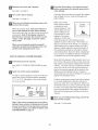
The decaJs shown here have been pJaced on the treadmill.
If a decal is missing, or if it is not legibJe, call the toil-free
teJephone number on the front cover of this manual and
order a free replacement decal Apply the deca! in the Jocation shown. Note: The decaJs are not shown at actuaJ size.
Plotect yourself a_ld
others from risk of serious
iniury. Read the user's
manual and :
side rails when
,Stand only on the
startir,g e stopping
t_ead_kll
-Charadespeed in
small inc,eme_ts
-Hold handrails to
safety clip while
o#eraUr_gtreadmill
,Stop if you feel faint,
dizzy¸ or _hort of
b_ea_h
KEEPHANDSANDFEETAWAY
FROMTHISAREAWHILETHE
TREADMILL
ISINOPERATION.
• F_lly _gage sto_age
latch before treadmill _ m_ved or
stored¸
,Reduce _cl_n_ to it_
lowest level before
folding treadmill into
storage posit_on
herin use
,Kee# clo hing,
fingers, and hair
away f_om rY®ving
belt¸
• Neve_try to adjust
o_ fix the belt while
i_is movin_
• Alwayswear
athletic shoesw_le
opera_ir_gt_eadmill
BEFORE YOU BEGIN
Thank you for seUecting the new HeaUthRide¢_H 550i
treadmill The HeaUthRider H 550i treadmHUoffers an
impressive array of features designed to heUpyou
achieve your fitness goaUs in the convenience of your
home. And when you're not exercising, the unique
H 550i treadmHUcan be foUded up, requiring Uessthan
haft the floor space of other treadmHUs.
For your benefit, read this manual carefully before
you use the treadmill. Ufyou have questions after
reading this manual pUease see the front cover of this
manual To heUpus assist you, note the product modeU
number and sedaU number before calling. The model
number of the treadmill is HRTL77105.0. The serial
number can be found on a decal attached to the tread°
mill (see the front cover of this manual for the location).
To avoid a registration fee for any service needed
under warranty, you must register the treadmill at
www.healthriderservice.com/registration.
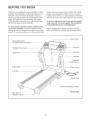
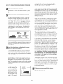
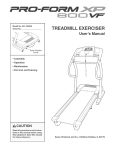
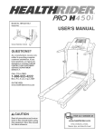
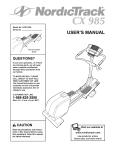
Before reading further, please review the drawing
below and familiarize yourself with the labeled parts.
Book Holder
Water Bottle Holder
(no water bottle is included)
Handgrip Pulse Sensor
Latch Knob
Console
Key/Clip
Handrail
Reset/Off
Breaker
Walking Belt
Foot Rail
Power Cord
Cushioned Walking Platform
To hire an authorized
service technician
to assemble the treadmill,
call toll-free 1-800-445-2480.
AssembJy requires two persons. Set the treadmHUin a cUeared area and remove aUU
packing materiaUs. Do not
dispose of the packing materiaUs untiUassembUy is compUeted. Assembly requires the incJuded allen wrenc h i
and your own phillips
screwdriver
(_L2_,
wire cutters _- _1.:>}>, and rubber mallet _
._'
Note: The underside of the treadmHUwaUking belt is coated with high-performance lubricant. During shipping, a
small amount of lubricant may be transferred to the top of the walking belt or the shipping carton. This is a normal
condition and does not affect treadmill performance. If there is lubricant on top of the walking belt, simply wipe off
the lubricant with a soft cloth and a mild, non-abrasive cleaner.
To identify
small parts during assembly,
use the part identification
3/4" Tek Screw (65)-2
drawings
1" Tek Screw (100)-4
below.
1 1/4" Tek Screw (118)-2
Nut (20)-2
Handrail Star
Washer (77)-2
Foot Screw (74)-2
Wheel Bolt (94)-2
Console Bolt (78)-2
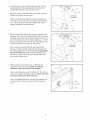
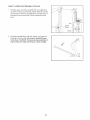
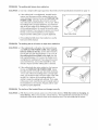
1. With the help of a second person, carefully raise the
Uprights (69) to the position shown.
Next, insert one of the Extension Legs (102) into the base
of the Uprights (69) as shown. Make sure that the
Extension Leg is turned so the Base Pad (99) is underneath it. Note: It may be helpful to tip the Uprights forward and use a rubber mallet to fully insert the Extension
Leg.
insert the other Extension Leg (not shown) in the same
way.
99
6
2, insert the tab on one of the Handrail Brackets (70) into
the indicated sbt in the right Upright (69), Attach the
Handrail Bracket with a 3/4" Tek Screw (65),
Attach the other Handrail Bracket (not shown) to the bft
Upright (not shown) the same way,
Console
Assembly
While a second person hoUdsthe consob assemMy, remove the Consob BoUts(78), the Handrail Star Washers
(77), and the Nuts (A) from both Uprights (69) and the
consob assemMy, Discard the Nuts,
3, While a second person hoUdsthe consob assemHy, insert
the upper end of one of the Handrails (55) into the consob
assemMy; make sure that the Handrail Bracket (70) is inside of the bwer end of the Handrail, Tighten a 1 1/4" Tek
Screw (118) into the bottom of the Handrail, Repeat with
the other Handrail on the bft side (not shown),
77
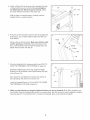
Console
Assembly
Next, insert two Consob BoUts(78) with Handrail Star
Washers (77) into the right Upright (69) and the Handrail
(55), Finger tighten the Console Bolts; do not fully tighten
the ConsoJe Bolts yet, Repeat with the Handrail on the
left side (not shown), After all four Console Bolts have
been started, tighten them,
With the help of a second person, carefully tip the
Uprights (69) down as shown, Make sure that the
Extension Legs (!02} remain in the Uprights.
69
Attach each Extension Leg (102) with two 1" Tek Screws
(100) and one Base Pad (99) as shown; attach the lower
Tek Screw, without the Base Pad, first,
Note: One replacement Base Pad may be included, Use
the Base Pad to replace any Base Pad that becomes
worn,
O0
_1
O2
Attacha Wheel(95)tothebaseoftheUprights(69)with
a WheelBolt(94)anda Nut(20),Donot overtighten
the WheetNut;the Whee!shouldturn freely.Attach
theotherWheel(notshown)inthesameway,
69
Withthehelpofa secondperson,carefullyraisethe
Uprights(69)toa verticalposition,
6, PresstheLockKnobSleeve(56)intotheleftUpright(69),
if necessary,
usea rubbermalletto fullyinserttheLock
KnobSleeve,
Knob
56
Removetheknobfromthepin,Makesurethatthe colar
andthe springareon the pin. Next,insertthepininto
theLockKnobSleeve(56)andtheleftUpright(69),and
tightentheknobbackontothepin,
69
7, Hacethetreadmillinthestorageposition(seeHOWTO
FOLDTHETREADMILL
FORSTORAGE
on page20),
identifytheRightEndcapFoot(50),AttachtheRight
EndcapFoottothebottomof theRightEndcap(58)with
a FootScrew(74),
Next,attachtheLeftEndcapFoot(49)tothebottomof
theLeftEndcap(96)witha FootScrew(74),
LowerthetreadmillFrame(110)(seeHOWTOLOWER
THETREADMILL
FORUSEonpage21),
7
49
\
74
11
8, Makesurethatal partsareproperlytightenedbeforeyou usethetreadmtLNote:Extrahardware
may
be included,Keeptheincludedallenwrenchina secureplace;theallenwrenchis usedtoadjustthewalking
belt(seepage23),Toprotecttheflooror carpetfromdamage,placea matunderthetreadmill,
HOW TO USE THE CHEST PULSE SENSOR
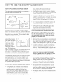
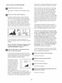
HOW TO PUT ON THE CHEST PULSE SENSOR
essary, draining the battery prematurely,
The chest pube sensor consists of two components-the chest strap and the sensor unit,
Store the chest pulse sensor in a warm, dry place,
Do not store the chest pulse sensor in a plastic bag
or other container that may trap moisture,
_Chest
Strap
Do not expose the chest pulse sensor to direct
sunlight for extended periods of time; do not expose
it to temperatures above 122 ° Fahrenheit (50 °
Celsius) or below 14 ° Fahrenheit (-10 ° Celsius),
Do not excessively bend or stretch the sensor unit
when using or storing the chest pulse sensor,
Sensor Unit'
Unit
insert the tab on one end of the chest strap into the
hob in one end of the sensor unit, as shown in the inset
drawing above, Press the end of the sensor unit under
the buckle on the chest strap, The tab should be flush
with the front of the sensor unit,
Next, wrap the chest
pulse sensor around
your chest and attach
the other end of the
chest strap to the
sensor unit, Adjust
the length of the
chest strap, if necessaG,, The chest pulse
sensor should be under your clothes, tight against your
skin, and as high under the pectoral muscles or
breasts as is comfortable, Make sure that the logo on
the sensor unit is facing forward and is right-side-up,
Pull the sensor unit away from your body a few inches
and locate the two electrode areas on the inner side
(the electrode areas are covered by shallow ridges),
Using saline solution such as saliva or contact lens so°
lution, wet both electrode areas, Return the sensor unit
to a position against your chest,
CHEST PULSE SENSOR CARE AND MAINTENANCE
Thoroughly dry the chest pulse sensor after each
use, The chest pulse sensor is activated when the
electrode areas are wetted and the heart rate
monitor is put on; the chest pulse sensor shuts off
when it is removed and the electrode areas are
dried, if the chest pulse sensor is not dried after
each use, it may remain activated longer than nee-
Clean the sensor unit using a damp cloth--never
use alcohol, abrasives, or chemicals, The chest
strap may be hand washed and air dried,
CHEST PULSE SENSOR TROUBLESHOOTING
The instructions on the following pages explain
how the chest puJse sensor is used with the console. If the chest puJse sensor does not function
properly, try the steps below.
Make sure that you are wearing the chest pulse sensor as described at the left, Note: if the chest pulse
sensor does not function when positioned as described, move it slightly lower or higher on your chest,
Use saline solution such as saliva or contact lens
solution to wet the two electrode areas on the
sensor unit, if heart rate readings do not appear until
you begin perspiring, rewet the electrode areas,
As you walk or run on the treadmill, position yourself near the center of the walking belt, For the
console to display heart rate readings, the user
must be within arm's tength of the console.
The chest pulse sensor is designed to work with
people who have normal heart rhythms, Heart rate
reading problems may be caused by medical
conditions such as premature ventricular contractions (pvcs), tachycardia bursts, and arrhythmia,
The operation of the chest pulse sensor can be
affected by magnetic interference caused by high
power lines or other sources, if it is suspected that
this is a problem, try relocating the treadmill,
The CR2032 battery may need to be replaced (see
page 24),
OPERATmON AND ADJUSTMENT
THE PRE-LUBRmCATED WALKmNG BELT
tric shock. This product is equipped with a cord having
an equipment-grounding conductor and a grounding
plug. Plug the power cord into a surge suppressor,
and plug the surge suppressor into an appropriate
outlet that is property installed and grounded in
accordance with aH JocaJ codes and ordinances.
Your treadmHUfeatures a waUking beUtcoated with high°
performance Uubdcant. IMPORTANT: Never apply silicone spray or other substances to the walking
belt or the walking platform. Such substances will
deteriorate the walking belt and cause excessive
wear.
Important: The treadmill
GFCl-equipped outJets.
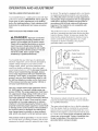
HOW TO PLUG IN THE POWER CORD
is not compatible
with
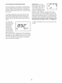
This product is for use on a nominal 120-volt circuit,
and has a grounding plug that looks like the plug illustrated in drawing 1 below. A temporary adapter that
looks like the adapter illustrated in drawing 2 may be
used to connect the surge suppressor to a 2-pob
receptacle as shown in drawing 2 if a properly
grounded outlet is not available.
of the equJpmentogrounding
conductor can
result in an increased risk of electric shock.
Check with a qualified electrician or serviceman if you are in doubt as to whether the
product is properly grounded. Do not modify
the plug provided with the product--if
it will
not fit the outlet, have a proper outlet
installed by a qualified electrician.
I
_-I
Your treadmill, like any other type of sophisticated
electronic equipment, can be seriously damaged by
sudden voltage changes in your home's power.
Voltage surges, spikes, and noise interference can
result from weather conditions or from other appliances being turned on or off. To decrease the possibility of your treadmill being damaged, aJways
use a surge suppressor with your treadmill (see
drawing 1 at the right). To purchase a surge suppressor, see your Jocal NeaJthRider dealer or can
the toil-free telephone number on the front cover
of this manuaJ and order part number 146148, or
see your tocal electronics store.
-Grounded
Outlet Box
_
Surge Suppressor
... Grounding Pin
2
_rounded Outlet Box
Adapter
Surge Suppressor
Use onJy a singJe-ouflet surge suppressor that is
UL 1449 listed as a transient voltage surge suppressor (TVSS). The surge suppressor must have a
UL suppressed voltage rating of 400 voJts or tess
and a minimum surge dissipation of 450 jouJes.
The surge suppressor must be eJectdcaHy rated for
120 volts AC and !5 amps. There must be a monitoring Jight on the surge suppressor to indicate
whether it is functioning properly. Failure to use a
properly functioning surge suppressor couM result
in damage to the controJ system of the treadmill. If
the control system is damaged, the walking belt
may change speed, accelerate or stop une×pectedty, which may result in a fan and serious injury.
The temporary adapter should be used only until a
properly grounded outlet (drawing 1) can be installed
by a qualified electrician,
This product must be grounded, if it should maffunc°
tion or break down, grounding provides a path of least
resistance for electric current to reduce the risk of sbc°
grounded
The green-colored rigid ear, lug, or the like extending
from the adapter must be connected to a permanent
ground such as a properly grounded outlet box cover,
Whenever the adapter is used it must be held in place
by a metal screw. Some 2-poJe receptacle outJet box
covers are not grounded. Contact a qualified electrician to determine if the outlet box cover is
10
before using an adapter.
]
pERSONAL
TRAINER
_
1
CREI\T[ _ YOUR OWN
/
2
12 I
',
Matrix
Priority Dbplay
,,:":.:;i"..../
/
\
_
_AN
,
t
_,
'ERSQN
"
\_
L
A Nt:R
',
I
[_'!_
(
I
,
1
/
H
','
'C
"_ 2
"
OneTuu_h
3
--
OneTo,_ch
3
",i
4
J
mN
CLm_E_
.......
4
,
2
STAR[
'
5
6
5
SPEED
6
'k_
_
_
_
EA
T
/_ E CON
;
,
7
9
'
8
9
DE/
/
10
"
10
/
/
L)ISPL/W
/
/
,'"
_
8
.......
7
g
J
//
;:
,/
//
}
11
12
o;
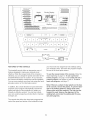
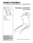
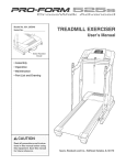
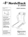
FEATURES OF THE CONSOLE
your heart rate near target heart rate settings during
your workouts, Note: The heart rate programs require
the use of the chest pulse sensor,
The treadmill console offers an impressive array of
features designed to make your workouts more
effective, When the manual mode of the console is
selected, you can change the speed and incline of the
treadmill with the touch of a button, As you exercise,
the console will display continuous exercise feedback,
You can even measure your heart rate using the hand°
grip pulse sensor or the chest pulse sensor,
To use the manual mode of the console, follow the
steps beginning on page 12, To use a personal
trainer program, see page 14, To create and use a
custom program, see pages 15 and 16, To use a
heart rate program, see page 17,
Note: If there is a sheet of c_ear plastic on the face
of the console, remove the plastic. To prevent damage to the walking p_atform, a_ways wear clean
shoes while using the treadmill. The first time the
treadmill is used, observe the alignment of the
walking beR, and center the walking be_t if necessary (see page 23).
in addition, the console features ten personal trainer
programs, Each program automatically controls the
speed and incline of the treadmill as it guides you
through an effective workout, You can even create
your own custom programs and store them in memory
for future use,
The console also offers four heart rate programs that
control the speed and incline of the treadmill to keep
11
HOW TO TURN ON THE POWER
walking belt as desired by pressing the Speed increase and decrease buttons, Each time a button
Hug in the power cord
(see page 10), Next, locate
the reset/off circuit breaker
on the treadmill near the
is pressed, the speed setting wiii change by 0,1
mph; if a button is held down, the speed setting
wiii change in increments of 0,5 mph, Note: After
the buttons are pressed, it may take a moment for
the walking belt to reach the selected speed setting,
power cord, Make sure that
the circuit breaker is in the
reset position,
Position
Reset
if one of the twelve numbered speed buttons is
pressed, the walking belt wiii gradually increase in
speed until it reaches the selected speed setting,
Next, stand on the foot rails of the treadmill, Find the
clip attached to the key (see the drawing on page 11 ),
and slide the clip onto the waistband of your clothes,
Then, insert the key into the console; after a moment,
the matrix and the display wiii light, Important: In an
emergency situation, the key can be pulled from
the console, causing the walking belt to slow to a
stop. Test the clip by carefully taking a few steps
backward; if the key is not pulled from the console,
adjust the position of the clip.
NOW TO USETHE
To stop the walking belt, press the Stop button, To
restart the walking belt, press the Start button, the
Speed increase button, or one of the twelve numbered buttons,
Change the incline of the treadmill
as desired.
To change the incline of the treadmill, press the
Incline increase and decrease buttons, Each time
a button is pressed, the incline will change by
0,5%, Note: After the buttons are pressed, it may
take a moment for the treadmill to reach the selected incline setting,
MANUAL MODE
Insert the key into the console.
Follow your progress with the matrix and the
display.
See HOW TO TURN ON THE POWER above.
When the manual mode
is selected, the matrix
wiii show a track representing 1/4 mile, As you
[]
walk or run on the tread°
mill, the indicators
around the track wiii appear in succession until
the entire track appears,
The track wiii then disappear and the indicators wiii
again begin to appear in succession,
Select the manuaJ mode.
Each time the key is inserted, the manual
mode wiii be selected
and a track will appear
in the matrix, if a program has been selected, reselect the
manual mode by removing the key from
the console and then reinserting it,
The lower left corner of
the display wiii show the
Start the waJking belt.
calories you have
burned and the incline
level of the treadmill,
To start the walking belt, press the Start button,
the Speed increase button, or one of the twelve
When you use the handgrip pulse sensor or the
chest pulse sensor, the lower left corner of the display will also show your heart rate,
if the Start button or the Speed increase button is
pressed, the walking belt will begin to move at 1
mph, As you exercise, change the speed of the
12
The lower right corner
of the display wiii show
the distance that you
SoLJsP_Eo
have walked or run,
the elapsed time, your
pace in minutes per
mile, and the speed of the walking belt, Note:
When a program is selected (except for custom
programs and heart rate program 13), the lower
right corner of the display will show the time rein the program instead of the elapsed
time,
Next, stand on
the foot rails
and hold the
metal contacts-avoid
The center of the dis°
reading, continue
15 seconds.
'.S5°'s'
1,,
moving your
hands, When
Contacts
your pulse is detected, the heart
symbol in the
lower left corner of the display will appear, one or
two dashes will appear, and then your heart rate
will be shown, For the most accurate heart rate
play is the priority dis°
play, Press the Display
button repeatedly until
the priority display
shows the information
to hotd the contacts
for about
Turn on the fans if desired.
To turn on the fans, press the Fan button, To turn
on the fans at high speed, press the button a second time, To turn off the fans, press the button a
third time, Note: if the fans are left on when the
that you want to view, Note: While information is
displayed in the priority display, the same information wiii not be displayed in the lower left or right
corner of the display,
walkin 9 belt is stopped, the fans will automatically
turn off after a few minutes,
Note: The console can display speed and distance in either miles or kilometers, To change the
unit of measurement, see THE iNFORMATiON
MODE/DEMO MODE on page 19, Note: For simplicity, all instructions in this section refer to
miles,
When you are finished
key from the consote,
exercising,
remove the
Step onto the foot rails, press the Stop button, and
adjust the incline of the treadmill to the lowest
setting. The incline must be at the towest setting
when the treadmii! is fotded to the storage pos6
tion or the treadmill will become damaged. Next,
remove the key from the console and put it in a secure place, Note: If the display remains tit after
the key is removed, the eonsoJe is in the
"demo" mode. See page 19 and turn off the
demo mode.
To reset the display, press the Stop button, remove the key, and then reinsert the key,
Measure your heart rate if desired.
Note: if you use the handgrip pulse sensor and
the chest pulse sensor at the same time, the consob will not display your heart rate accurately,
When you are finished using the treadmill,
switch the reseL/off circuit breaker to the "off"
To use the handgrip pulse sensor, first remove the
sheets of clear plastic from the metal contacts, in
addition, make sure that your hands are clean,
position
13
and unptug the power cord.
settings for the next several segments wiii be
shown in the columns to the right,
HOW TO USE A PERSONAL TRAINER PROGRAM
mnsert the key into the console.
When only three seconds remain in the first segment of the program, both the Current Segment
column and the column to the right will flash and a
series of tones will sound, if the speed and/or incline of the treadmill is about to change, the speed
setting and/or the incline setting wiii flash in the
display to alert you,
See HOW TO TURN ON THE POWER on page
12.
Select one of the personal
trainer programs.
To select a personal trainer program, press the
Certified Personal Trainer Programs button repeatedly; "P-1 ," "P-2," "P-3," "P-4," "P-5," "P-6,"
"P-7," "P-8," "P-9," or "P-IO" will appear in the priority display for a few seconds. In addition, the
maximum incline setting of the program and the
maximum speed setting of the program will flash
in the display for a few seconds. A profile of the
speed settings of the program will scroll across
the matrix.
When the first segment is completed, allepeed
ee4@7_5"v/i//move one coidmn to the ie,_t.The
speed setting for the second segment will then be
shown in the flashing Current Segment column,
and the treadmill will automatically adjust to the
speed and incline settings for the second segment. Note: if all seven of the indicators in the
Current Segment column are lit, the epeed'ee4_i_'9':¢
maymove downwafdso that only the highest indicators appear in the matrix.
The program wiii continue in this way until the
speed setting for the last segment is shown in the
Current Segment column and the last segment
ends, The walking belt wiii then slow to a stop,
:23
LJoP.J
P,oG,,_,, 'U.&J
t.JJLJ&JLJ
3S_ED
if the speed or incline setting for the current segment is too high or too low, you can manually
override the setting by pressing the Speed or
Incline buttons, Every few times a Speed button is
pressed, an additional indicator wiii appear or disappear in the Current Segment column; if any of
the columns to the right of the Current Segment
column have the same number of lit indicators as
A few seconds after a personal trainer program is
selected, the display will show how long the program will last,
Press the Start button or the Speed increase
button to start the program.
the Current Segment column, an additional indicator may appear or disappear in those columns as
well. Important: When the current segment of
the program ends, the treadmill will automatically adjust to the speed and incline settings
for the next segment.
A moment after the button is pressed, the treadmill will automatically adjust to the first speed and
incline settings of the program, Hold the handrails
and begin walking,
Each program is divided into either 30 or 60 oneminute segments, One speed setting and one incline setting are programmed for each segment,
Note: The same speed setting and/or incline setting
may be programmed for two or more consecutive
segments,
The speed setting for
the first segment wiii
be shown in the flash-
To stop the program at any time, press the Stop
button. To restart the program, press the Start button or the Speed increase button. The walking belt
will begin to move at 1 mph. When the next segment of the program begins, the treadmill will automatically adjust to the speed and incline settings
for the next segment.
Current
Segment
Fottow your progress with the disptay.
ing Current Segment
column of the matrix,
(The incline settings
are not shown in the
See step 5 on page 12.
PROGRAtd
matrix,) The speed
14
Measure your heart rate if desired.
Press the Start button or the Speed increase
button and program the desired speed and incline settings.
See step 6 on page 13.
A moment after the button is pressed, the walking
belt will begin to move. Hold the handrails and
begin walking.
Turn on the fans if desired.
See step 7 on page 13.
When you are finished
key from the console.
exercising,
Refer to the matrix.
Each custom program
is divided into one=
remove the
minute segments. One
speed setting and one
I
Segment
incline setting can be
CUSTOM PROGRAm4
programmed for each
segment. The speed
setting for the first segment will be shown in the flashing Current
Segment column of the matrix. (The incline settings are not shown in the matrix.) To program a
speed setting and an incline setting for the first
segment, simply adjust the speed and incline of
the treadmill as desired by pressing the Speed
and Incline buttons. Every few times a Speed button is pressed, an additional indicator will appear
or disappear in the Current Segment column.
When the program ends, make sure that the incline of the treadmil! is at the lowest setting.
Next, remove the key from the consob and put it in
a safe pUace.Note: If the display remains lit
after the key is removed, the console is in the
"demo" mode. See page 19 and turn off the
demo mode.
When you are finished using the treadmill,
switch the reset/off circuit breaker to the "off"
position and unplug the power cord.
HOW TO CREATE A CUSTOM PROGRAM
When the first segment of the program ends, a series of tones wiii sound and the current speed setting and the current incline setting will be saved in
memory. The t,#Feeco/umne of /hd/_wtoFe v/ill then
mo_:e one column to the left, and the speed setting for the second segment will be shown in the
flashing Current Segment column. Program a
speed setting and an incline setting for the second
segment as described above.
Insert the key into the console.
See HOW TO TURN ON THE POWER on page
12.
Select one of the custom programs.
To sebct a custom program, press the Custom &
Heart Rate ControU Programs button repeatedUy;
"P=I 1" or "P=12" wHUappear in the priority display
for a few seconds.
p
CUSTOM
P,OG.A_
Continue programming speed and incline settings
for as many segments as desired; custom programs can have up to forty segments. When you
are finished with your workout, press the Stop button twice. The speed and incline settings that you
have programmed and the number of segments
that you have programmed wiii then be saved in
memory.
d
LJ.U
ZJ.ZJ
U.ZJ _
Current
'
ZJo_ s_D
When you are finished
key from the consote.
Note: If the custom program has not yet been
defined, three columns of indicators will scroll
across the matrix, if more than three columns
of indicators appear, see HOW TO USE A CUSTOM PROGRAM on page 16.
See step 7 on this page.
15
exercising,
remove the
HOW TO USE A CUSTOM PROGRAM
in the matrix,) The speed settings for the next four
segments are shown in the columns to the right,
mnsert the key into the console.
When only three seconds remain in the first segment of the program, both the Current Segment
column and the column to the right will flash, a
series of tones will sound, and the speed setting
and the incline setting wiii flash in the display.
When the first segment ends, aiispe.e.d'seLff/7ds
wiii mo_'e,one co/dmn to tA_eie_ The speed setting
for the second segment will then be shown in the
flashing Current Segment column, and the treadmill will automatically adjust to the second speed
and incline settings that you programmed previously.
See HOW TO TURN ON THE POWER on page
12.
Select one of the custom
programs.
To sebct a custom program, press Custom &
Heart Rate ControU Programs button repeatedUy;
"P-11" or "P-12" wHUappear in the priority dispUay
for a few seconds, in addition, the maximum indine setting of the program and the maximum
speed setting of the program wHUflash in the dispUayfor a few seconds. A profile of the speed settings of the program wHUscroll across the matrix.
p
t
_oLJ
The program will continue in this way until the
speed setting for the last segment is shown in the
Current Segment column and the last segment
ends. The walking belt wiii then slow to a stop.
t
" LJ.LJULJ
if desired, you can redefine to the program while
using it. To change the speed or incline setting
for the current segment, simply press the Speed
or Incline buttons. When the current segment ends,
the new setting will be saved in memory. To increase the length of the program, first wait until
the program is completed. Then, press the Start button and program speed and incline settings for as
many additional segments as desired. When you
have added as many segments as desired, press
the Stop button twice. To decrease the Jength of
the program, press the Stop button twice at any
time before the program is completed.
"
_.&JSPEED
A few seconds after a custom program is sebcted, the display will show how long the program
will last.
Note: if only three columns of indicators scroll
across the matrix, see HOW TO CREATE A
CUSTOM PROGRAM on page 15.
To stop the program at any time, press the Stop
button, To restart the program, press the Start button or the Speed increase button,
Press the Start button or the Speed increase
button to start the program.
A moment after the button is pressed, the treadmill will automatically adjust to the first speed and
incline settings that you programmed previously.
Hold the handrails and begin walking.
Fottow your progress with the display.
See step 5 on page 12.
Measure your heart rate if desired.
Each custom program
is divided into several
Current
Segment
See step 6 on page 13.
I ad-
One speed setting and
one
programmed for each
CUSTOM PROGRAM
segment. (The same
speed setting and/or
incline setting may be
programmed for two or more consecutive segments.) The speed setting for the first segment wiii
be shown in the flashing Current Segment column
of the matrix. (The incline settings are not shown
Turn on the fans if desired.
See step 7 on page 13.
When you are finished
key from the consote.
See step 7 on page 15.
16
exercising,
remove the
.OWTO
USE
A.EART
RATE
PROGRAM
Enter a target heart rate setting.
If heart rate program
13 is selected, the target heart rate setting for
the entire program will
flash in the priority display, If desired, press
the increase and decrease buttons beside the Custom & Heart Rate
CA UTI O N: ifyouhove
heart
prob=
!
lems, or if you are over 60 years of age and
have been inactive, do not use the pulse programs. If you are taking medication regularly,
consult your physician to find whether the
medication will affect your exercise heart rate.
Control Programs button to change the target
heart rate setting (see EXERCISE INTENSITY on
page 25}.
Follow the steps bebw to use a heart rate program,
If heart rate program 14, 15, or !6 is selected,
the maximum target heart rate setting of the program will flash in the priority display, if desired,
press the increase and decrease buttons beside
the Custom & Heart Rate Control Programs button
to change the maximum target heart rate setting
(see EXERCISE INTENSITY on page 25}. Note:
If the maximum target heart rate setting is
changed, the intensity level of the entire program
will change,
Put on the chest pulse sensor.
You must wear the chest pulse sensor to use a
pulse program.
Insert the key into the consote.
See HOW TO TURN ON THE POWER on
page 12,
Select one of the heart rate programs.
Press the Start button or the Speed increase
button to start the program.
To sebct a heart rate program, press the Custom
& Heart Rate Control Programs button repeatedly;
"P-13/"P-14," "P-15# or "P-16," will appear in the
priority display for a few seconds,
A moment after the button is pressed, the treadmill will automatically adjust to the first speed and
incline settings of the program. Hold the handrails
and begin walking.
Heart rate program 13 is divided into 100 oneminute segments. The same target heart rate setting is programmed for all segments. (For a
shorter workout, simply stop the program before it
ends.) Heart rate programs 14, 15, and 16 are divided into either 20 or 30 one-minute segments.
One target heart rate setting is programmed for
each segment. Note: The same target heart rate
setting may be programmed for two or more consecutive segments.
p
rl rl_cu.E
LtoLJ
eu
L.MJ t.J _,.J
r_
_oU SPEED
If heart rate program !3 is selected, a pulse
symbol will scroll across the matrix (see the drawing above),
if heart rate program
14, 15, or 16 is selected, the target heart
rate setting for the first
segment will be shown
in the flashing Current
If heart rate program
14, 15, or 16 is selected, a profile of the
target heart rate settings of the program
will scroll across the
matrix,
Current
Segment
PULSE
PROGRAM
matrix, The target heart
rate settings for the next
several segments will be shown in the columns to
the right, When only three seconds remain in the
first segment of the program, both the Current
Segment column and the column to the right will
flash and a series of tones will sound,
17
/
When the first segment ends, allta,%etheaftrate
settings wiii move one coiumn tothe/eft.
The tar=
get heart rate setting for the second segment will
then be shown in the flashing Current Segment
column,
To stop the program at any time, press the Stop
button, To restart the program, press the Start button or the Speed increase button, The walking belt
will begin to move at 1 mph, When the console
compares your heart rate to the target heart rate
setting, the speed and/or incline of the treadmill
may automatically change to bring your heart rate
closer to the target heart rate setting,
During each heart rate program, the console wiii
regularly compare your heart rate to the target
heart rate setting, if your heart rate is too far
below or above the target heart rate setting for the
current segment, the speed of the walking belt will
automatically increase or decrease to bring your
heart rate closer to the target heart rate setting,
Follow your progress with the display.
See step 5 on page 12,
Turn on the fans if desired.
if the speed or incline setting is too high or too low
at any time during the program, you can adjust the
setting with the Speed or Incline buttons, However,
when the console compares your heart rate to the
target heart rate setting, the speed of the treadmill
may automatically change to bring your heart rate
closer to the target heart rate setting,
See step 7 on page 13,
When you are finished
key from the console.
See step 7 on page 15,
if your pulse is not detected during the program,
the letters "PLS" wiii flash in the display and the
speed of the treadmill may automatically
decrease, if this occurs, see CHEST PULSE SENSOR TROUBLESHOOTING on page 9,
18
exercising,
remove the
THE mNFORMATmONMODE/DEMO MODE
IMPORTANT: if a "d" appears in the lower left corner
of the display, the console is
in the "demo" mode. This
mode is intended to be used
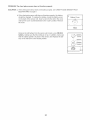
The console features an information mode that keeps
track of treadmHi usage information. The information
mode aiso allows you to select miles or kilometers as
the unit of measurement and to turn on and turn off the
demo mode.
only when a treadmill is displayed in a store. When the console is in the demo
mode, the power cord can be plugged in, the key can
be removed from the console, and the indicators in the
display will automatically appear in a preset sequence;
the buttons on the console will not operate. If a "d" appears when the information mode is selected, press
the Speed decrease button so the "d" disappears.
To select the information mode, hoid down the Stop
button while inserting the key into the console, and
then release the Stop button. When the information
mode is selected, the following information wHi be dispiayed:
play wiii show the
total number of
hours that the
treadmill has
been operated,
The lower right
corner of the dis°
To exit the information mode, remove the key from the
console.
Ce
E
play wiii show the
total number of miles or kilometers that the walking belt
has moved, An "E" for English miles or an "M" for metric
kilometers will appear in the lower left corner of the dis°
play, Press the Speed increase button to change the
unit of measurement if desired,
19
HOW TO FOLD AND MOVE THE TREADMILL
HOW TO FOLD THE TREADMILL
FOR STORAGE
Before folding the treadmill, adjust the incline to the
Jowest position, ff this is not done, the treadmill may be
permanently damaged. Next, unptug the power cord.
CAUTION: You must be able to safety tift 45 pounds (20
kg) to raise, Jower, or move the treadmi&
1, HoUdthe treadmHUwith your hands in the Uocations shown
by the arrow, CAUTION: To decrease the possibility of
injury, bend your legs and keep your back straight. As
you raise the treadmill, make sure to tift with your tegs
rather than your back. Raise the treadmHUabout haffway
to the vertical position,
2, Move your right hand to the position shown and hold the
treadmill firmly, Using your left hand, pull the latch knob
to the left and hold it, Raise the treadmill until the catch is
aligned with the pin on the latch knob, Slowly release the
latch knob, Make sure that the pin is fully inserted into
the catch.
Open
To protect the floor or carpet from damage, ptace a
mat under the treadmill. Keep the treadmill out of
direct sunlight. Do not leave the treadmill in the storage position in temperatures above 85 ° Fahrenheit.
Closed
HOW TO MOVE THE TREADMILL
Before moving the treadmill, convert the treadmill to the storage position as described above. Make sure that the pin
on the tatch knob is fully inserted into the catch.
1, Hold the uprights and place one foot against one of the
wheels,
2, Tilt the treadmill back until it rolls freely on the wheels,
Carefully move the treadmill to the desired location,
Never move the treadmill without tipping it back. To
reduce the risk of injury, use extreme caution while
moving the treadmi& Do not attempt to move the
treadmill over an uneven surface.
3, Place one foot against one of the wheels, and carefully
lower the treadmill to the storage position,
2O
Wheels
Base
HOW TO LOWER THE TREADMmLL FOR USE
1,
HoUdthe upper end of the treadmHUwith your right hand
as shown, Using your bft hand, pull the Uatehknob to the
bft and hoUdit, Pivot the treadmHUdown until the frame is
past the pin on the bck knob, SbwUy rebase the Uatch
knob,
Open
2,
Hold the treadmill firmly with both hands, and lower the
treadmill to the floor, Do not drop the treadmill frame
to the floor. CAUTION: To decrease the possibility of
injury, bend your tegs and keep your back straight.
21
/
TROUBLESHOOTmNG
Most treadmill problems can be solved by following the steps below. Find the symptom that applies, and
follow the steps listed, mffurther assistance is needed, see the front cover of this manual.
PROBLEM:
The power does not turn on
SOLUTmON: a, Make sure that the power cord is plugged into a surge suppressor, and that the surge suppressor
is plugged into a properly grounded outlet (see page 10). Use only a singleooutlet surge suppressor that meets all of the specifications described on page 10. important: The treadmill is not como
patible with GFCI-equipped outlets.
b. After the power cord has been plugged in, make sure that the key is inserted into the console.
C,
Check the circuit breaker located on the treadmill
near the power cord. if the switch protrudes as
shown, the circuit breaker has tripped. To reset the
circuit breaker, wait for five minutes and then press
the switch back in.
c
Reset
Tripped
PROBLEM:
The power turns off during use
SOLUTION:
a. Check the circuit breaker located on the treadmill frame near the power cord (see c. above), if the
circuit breaker has tripped, wait for five minutes and then press the switch back in.
b. Make sure that the power cord is plugged in. if the power cord is plugged in, unplug it, wait for
five minutes, and then plug it back in.
c. Remove the key from the console. Reinsert the key fully into the console.
d. if the treadmill still will not run, see the front cover of this manual.
PROBLEM:
The speed display on the console
does not function
properly
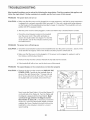
SOLUTmON: a, Remove the key from the console and UNPLUG THE
POWER CORD. Carefully tip the treadmill down as
shown at the right. Remove the 1" Screws (48) and
the 2" Screws (83) from the Hood (23). Then, raise
the Uprights (69) and carefully remove the Hood.
Next, locate the Reed Switch (10) and the Magnet (7)
on the left side of the Pulley (8). Turn the Pulley until
the Magnet is aligned with the Reed Switch. Make
sure that the gap between the Magnet and the
Reed Switch is about 1/8". if necessary, loosen the
Screw (27), move the Reed Switch slightly, and then
retighten the Screw. Reattach the hood, and run the
treadmill for a few minutes to check for a correct
speed reading.
22
_-
1/8'
Top
_-_
1,
L ]
_
48
PROBLEM:
The walking
SOLUTION:
a, Use onUya singb-outbt
b,
C,
belt slows when waJked on
surge suppressor that meets aH of the specifications described on page 10,
ff the waUking beUtis overtightened, treadmHUperformance may decrease and the waUking beUtmay become damaged, Remove the key and UNPLUG THE
POWER CORD, Using the allen wrench, turn both
rear roller bouts counterclockwise, 1/4 of a turn, When
the waUking beUtis propedy tightened, you shouUd be
abb to Hft each edge of the waUking beUt3 to 4 inches
off the waUking pUatform, Be carefuU to keep the waUking beUtcentered, Then, pUugin the power cord, insert
the key, and run the treadmill for a few minutes,
Repeat until the walking belt is properly tightened,
Rear Roller Bolts
If the walking belt still slows when walked on, see the
front cover of this manual,
PROBLEM:
The walking
heft is off-center
or slips when walked on
SOLUTION:
a, If the walking belt is off-center, first remove the key
and UNPLUG THE POWER CORD, If the walking
belt has shifted to the Jeft, use the allen wrench to
turn the left rear roller bolt clockwise 1/2 of a turn; if
the walking beJt has shifted to the right, turn the
bolt counterclockwise 1/2 of a turn, Be careful not to
overtighten the walking belt, Then, plug in the power
cord, insert the key, and run the treadmill for a few
minutes, Repeat until the walking belt is centered,
b,
if the walking belt slips when walked on, first remove
the key and UNPLUG THE POWER COBB, Using
the allen wrench, turn both rear roller bolts clockwise,
1/4 of a turn, When the walking belt is correctly tight°
ened, you should be able to lift each edge of the walking belt 3 to 4 inches off the walking platform, Be
careful to keep the walking belt centered, Then, plug
in the power cord, insert the key and carefully walk on
the treadmill for a few minutes, Repeat until the walking belt is properly tightened,
PROBLEM:
The incline of the treadmill
does not change correctly
SOLUTION:
a, With the key in the console, press one of the Incline buttons, While the incline is changing, remove the key. After a few seconds, reinsert the key, The treadmill will automatically rise to the
maximum incline level and then return to the minimum level, This will recalibrate the incline,
23
PROBLEM:
The chest pulse sensor does not function
properly
SOLUTION:
a, if the chest pulse sensor does not function properly, see CHEST PULSE SENSOR TROUBLESHOOTING on page 9,
b, if the chest pulse sensor still does not function properly, the battery
should be changed, To replace the battery, locate the battery cover
on the back of the sensor unit, insert a coin into the slot in the cover
and turn the cover counterclockwise to the "open" position, Remove
the cover,
Remove the old battery from the sensor unit, insert a new OR 2032
battery, making sure that the writing is on top, in addition, make sure
that the rubber gasket is in place in the sensor unit, Replace the battery cover and turn it to the closed position,
b
Battery Cover
Battery
Cover
I
i
z Battery
Rubber
24
CONDiTiONiNG
&WARNING:
GUiDELiNES
Before
beginning
th s
or any exercise program, consuJt your physi=
clan. This is especially important for individuals over the age of 35 or individuals with preexisting health problems.
For maximum fat burning, adjust the speed and incline
of the treadmill until your heart rate is near the middle
number in your training zone,
The putse sensors are not medical devices.
Various factors, including the user's movement, may affect the accuracy of heart rate
readings. The pulse sensors are intended
only as e×ercise aids in determining
heart rate
trends in general
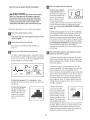
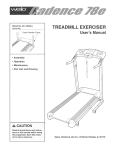
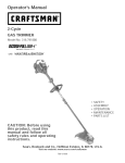
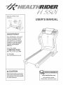
Aerobic
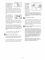
EXERCISE iNTENSiTY
WORKOUT
Whether your goal is to burn fat or to strengthen your
cardiovascular system, the key to achieving the
desired results is to exercise with the proper
The proper intensity level can be found by using your
heart rate as a guide, The chart below shows recom=
mended heart rates for fat burning and aerobic exercise,
HEART
RATE
TRAmMNG
155
t45
140
130
t25
1!5
MAX
145
138
I30
125
118
110
103
125
120
1t5
110
105
95
90
20
30
40
50
60
70
80
FAT BURN
FAT BURN
Age
GUiDELiNES
Each workout should include the following three parts:
A Warm-up--Start
each workout with 5 to 10 minutes
of stretching and light exercise, A proper warm-up in=
creases your body temperature, heart rate and circula=
tion in preparation for exercise,
ZONES
165
Exercise
if your goal is to strengthen your cardiovascular system, your exercise must be "aerobic," Aerobic exercise
is activity that requires large amounts of oxygen for
prolonged periods of time, This increases the demand
on the heart to pump blood to the muscles, and on the
lungs to oxygenate the blood, For aerobic exercise,
adjust the speed and incline of the treadmill until your
heart rate is near the highest number in your training
zone.
The following guidelines wiii help you to plan your ex=
ercise program, For more detailed exercise informa=
tion, obtain a reputable book or consult your physician,
AEROBIC
begin to use stored fat caiorie,_for energy, if your goal
is to burn fat, adjust the speed and incline of the treadmill until your heart rate is near the lowest number in
your training zone,
Training Zone Exercise--After
warming up, increase
the intensity of your exercise until your pulse is in your
training zone for 20 to 60 minutes, (During the first few
weeks of your exercise program, do not keep your
pulse in your training zone for longer than 20 minutes,)
Breathe regularly and deeply as you exercise--never
hold your breath,
To find the proper heart rate for you, first find your age
near the bottom of the chart (ages are rounded off to
the nearest ten years), Next, find the three numbers
above your age, The three numbers define your "train=
ing zone," The lower two numbers are recommended
heart rates for fat burning; the higher number is the
recommended heart rate for aerobic exercise,
A CooFdown--Finish
each workout with 5 to 10 min-
utes of stretching to cool down, This will increase the
flexibility of your muscles and will help prevent post-exercise problems,
EXERCISE FREQUENCY
Fat Burning
To maintain or improve your condition, complete three
workouts each week, with at bast one day of rest between workouts, After a few months, you may corn=
plete up to five workouts each week if desired, The key
to success is to make exercise a regular and enjoyable
part of your everyday life,
To burn fat effectively, you must exercise at a relatively
low intensity level for a sustained period of time,
During the first few minutes of exercise, your body
uses easily accessible carbof_dr3te c3/'oriesfor en=
ergy, Only after the first few minutes does your body
25
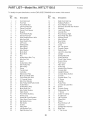
PART LiST--Model
No. HRTL77105.0
Rt005A
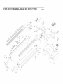
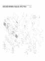
To identify the parts Hsted beUow,see the EXPLODED DRAWUNG in the center of this manual
Key
No.
Qty.
Key
No.
Qty.
1
2
3
4
5
2
2
1
1
2
Foot Rail Insert
Foot Rail
Front Roller Nut
Left Foot Rail Cap
Frame Pivot BoUt
51
52
53
54
55
1
1
2
1
2
6
7
8
9
10
11
12
13
2
1
1
4
1
1
1
1
Frame Pivot Spacer
Magnet
Lift Frame
56
57
58
59
60
61
62
63
1
1
1
2
1
1
1
4
14
15
16
17
18
19
20
1
1
1
1
1
2
4
WaUking BeUt
UdUerSpring
Drive Motor
UdUerWasher
Motor BeUt
Motor BoUt
Nut
64
65
66
67
68
69
70
1
10
1
2
1
1
2
21
22
23
24
25
26
27
28
29
30
31
1
1
1
1
1
1
7
1
1
1
1
UncHneMotor BoUt,Top
UdUerArm Nut
Hood
UncHneMotor BoUt
UdUerPulley Nut
UdUerPulley
Screw
Transformer
Controller
Electronics Plate
Motor Controller Wire
71
72
73
74
75
76
77
78
79
80
81
1
1
1
2
1
2
4
4
2
1
1
32
33
34
1
4
1
Front Roller Adj, Bolt
2" Console Screw
Idler Pivot Washer
82
83
84
1
2
1
35
36
37
38
39
40
3
1
1
1
1
1
Idler Pulley BoWHatform Bolt
Incline Motor
Incline Motor Stop
Motor Belly Pan
Idler Pulley Washer
Static Decal
85
86
87
88
89
90
4
1
14
88
1
4
Console Base, Top
2" Screw
Key/Clip
Pulse Plate
Console Ground Wire
Screw
Console Screw
Releaseable Tie
1" Screw
41
42
43
44
45
46
47
48
49
50
1
1
1
2
4
2
2
1
1
1
Front Roller Bushing
Power Cord
Reset/Off Circuit Breaker
Short Hood Cover Screw
Belt Guide Screw
Belt Guide
Isolator
Pulse Wire
Left Endcap Foot
Right Endcap Foot
91
92
93
94
95
96
97
98
99
100
2
5
2
2
2
1
1
1
6
16
Cable Tie Clamp
8" Cable Tie
Lift Pivot Bolt
Wheel Bolt
Wheel
Rear Endcap, Left
Grommet
Upright Wire Harness
Base Pad
1" Tek Screw
Description
Frame Pivot Nut
Reed Switch/Sensor
UdUerArm BoUt
Wire
26
Description
Right Foot Rail Cap
Walking Platform
Front Platform Screw
Electronic Bracket Star Washer
Handrail
Lock Knob Sleeve
Ground Wire
Rear Endcap, Right
Rear Roller Adj, Bolt
Warning Decal
Allen Wrench
Rear Roller
Pulse Base
Catch
3/4" Tek Screw
Console Frame
Platform Nut
Latch Pin Assembly
Upright
Handrail Bracket
Pulse Receiver
Chest Pulse Sensor
Sensor Strap
Foot Screw
Filter Wire
Pulse Grip
Handrail Star Washer
Console Bolt
Upright Endcap
Console Base, Bottom
Console
101
102
103
104
105
106
107
108
109
110
111
112
113
114
1
2
2
2
2
1
1
1
1
1
6
2
1
2
Left Fan Grill
115
116
117
118
#
#
#
#
#
#
#
#
Extension Leg
Extension Cap
Incline Warning Decal
Console Fan
Right Cup Holder
Left Cup Holder
Book Holder
Power Cord Grommet
Frame
3/4" Screw
Roller Star Washer
Right Fan Grill
Isolator Strip
1
1
4
2
1
1
1
1
1
1
1
1
Hood Cover
Idler Arm
Uonut
1 1/4" Tek Screw
12" White Wire, M/F
8" White Wire, 2F
4" Blue Wire, 2F
4" Black Wire, 2F
12" Green Wire, 2 Ring
4" Green Wire, F/2 Ring
8" Red Wire, M/F
User's Manual
# These parts are not illustrated
27
EXPLODED
DRAWHNG--ModeM No. HRTL77105.0
RlOOSA
27
34
88
29
27
39
75
32
3
9
_
6"
_•
24
52
83
14
88
61
96
45
62
59
58
74
112
_74
67
EXPLODED
DRAWING--Model
87 :
No. HRTL77105.0
moosA
7o
%
93
88
111
65
"-:
\&
88
\
/
lo4
_€
87
105
20
87
I
95
102
'i
1oo
_
_99
Y
1o2
IOO
85
___
jJ
44
111
90
"\
44
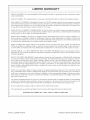
LiMiTED WARRANTY
WHAT IS COVERED--The
riaI and workmanship.
WHO
iS COVERED--The
entire HealthRider
original
'_ H550i treadmill
purchaser
or any person
("Product")
receiving
is warranted
the Product
to be free of all defects
as a gift from the original
purchaser.
HOW LONG IS IT COVERED--ICON
Health & Fitness, Inc. ("ICON"), extends a twelve (12) year warranty
motor after the date of purchase. The belt and deck are covered for one (1) year after the date of purchase.
icaI components
are covered for one (1) year after the date of purchase.
(1) year after the date of purchase. Labor is covered for one (1) year.
All electrical
components
in mate-
on the drive
All mechan-
are covered
for one
WHAT WE DO TO CORRECT
COVERED
DEFECTS--We
will ship to you, without charge, any replacement
part or
component,
providing the repairs are authorized
by ICON first and are performed
by an ICON trained and authorized
service provider, or, at our option, we wilI replace the Product.
WHAT iS NOT COVERED--Any
failures or damage caused by unauthorized
service, misuse, accident, negligence,
im_
proper assembly or installation,
alterations,
modifications
without our written authorization
or by failure on your part to
use, operate, and maintain as set out in your User's Manual ("Manual"). This warranty does not extend to products used
for commercial
WHAT
YOU
or rental purposes
MUST
or to products
DO--Always
retain
proof
used as store display
of purchase,
such
modules.
as your
bill of sale;
store,
operate,
and maintain
the
Product as specified in the Manual; notify our Customer
Service Department
of any defect within 10 days after discow
ery of the defect; as instructed,
return any defected part for replacement
or, if necessary, the entire product, for repair.
USER'S
MANUAL--It
is VERY
Remember to do the periodic
continued
satisfaction.
HOW TO GET PARTS
IMPORTANT
maintenance
THAT
YOU
requirements
AND SERVICE--Simply
READ
specified
caII our Customer
THE
MANUAL
in the ManuaI
Service
before
to assure
Department
operating
proper
the
operation
at 1°888_922-4222
Product.
and your
and te!l them
your name and address and the seriaI number of your Product. They will tell you how to get a part replaced, or if neces_
sary, arrange for service where your Product is located or advise you how to ship the Product for service. Before ship_
ping, always
your Product
obtain a Return Authorization
Number (RA No.) from our Customer
Service Department;
(save the originaI shipping carton if possible);
put the RA No. on the outside of the carton
product, include a letter explaining
vice is covered by warranty.
ICON is not responsible
the product
or liable for indirect,
or problem
special
and a copy
or consequential
of your proof
damages
of purchase
arising
securely pack
and insure the
if you believe
out of or in connection
the ser-
with the
use or performance
of the product or damages with respect to any economic Ioss, loss of property, loss of revenues or
profits, loss of enjoyment
or use, costs of removal, installation
or other consequential
damages of whatsoever
nature.
Some
itation
states do not ailow the exclusion
may not apply to you.
The warranty extended hereunder
or fitness for a particular purpose
allow
limitations
This warranty
to change,
gives you specific
of incidentai
or consequenfiaI
damages.
Accordingly,
the above lim_
is in lieu of any and all other warranties
and any implied warranties
of merchantability
is limited in its scope and duration to the terms set forth herein. Some states do not
on how long an implied
No one is authorized
or limitation
warranty
lasts. Accordingly,
the above
modify or extend the terms of this limited
legal rights and you may have other
limitation
may not apply to you.
warranty.
rights which
vary from state to state.
iCON HEALTH & FITNESS, INC., 1500 S. 1000 W., LOGAN, UT 84321o9813
Part No, 229648 R1005A
Printed in USA © 2005 ICON IP, Inc,