1
Technical Data Sheet
New
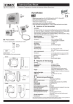
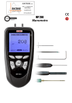
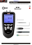
Pressure Transmitter
with large electroluminescent display
CPA 300
• Ranges from 0/+10 Pa to -10 000/+10 000 Pa (according to model)
• Transmitter resolution at 0.1 Pa on CPA 301 (optional)
• Configurable intermediate and centre zero ranges
• Air velocity and airflow functions (optional)
• Interchangeable measuring sensor (SPI technology)
• Simultaneous display of 1 to 4 parameters
• External transmitter inputs (KIMO Class 200 and 300)
• 2 analogue outputs 4-20 mA (4 wires) or 0-10 V, RS 232,
4 6A/230 Vac RCR relays (for Ref. CPA300)
2 6A/230 Vac RCR relays (for Ref. CPA300HV)
• Audible alarms (buzzer - 80 dB)
• Output diagnostics
• MODBUS network RS 485 system (optional)
• Multi-directional housing made of ABS V-0 as per UL 94
• Large display 50 x 190 mm
Part number
To order, just add the codes to complete the part number :
Measuring range
1
2
3
4
For the intermediate and
-100/+100 Pa
centre zero ranges, see
-500/+500 Pa
“Configuration”.
-1000/+1000 Pa
-10 000/+10 000 Pa
Power supply
24 Vac/dc 230 Vac
ou HV
CPA30
Example : CPA 301 HV
Pressure transmitter type CPA 300, with measuring range of -500/+500 Pa,
with power supply 230 Vac.
Transmitter features
Pressure
Measuring range ............................see “SPI features”
Units of measurement....................Pa, mmH2O, mbar, inWG, mmHG
Accuracy *.......................................±0,5% of reading ±1 Pa (CPA 301/302/303)
±0,5% of reading ± 0.8 Pa (CPA 301 with 0.1 Pa
option)
.........................................................±0,5% of reading ±10 Pa (CPA 304)
Zero drift .........................................none (see “self-calibration”)
Resolution ..........................................1 Pa - 0,1 mmH2O - 0,01 mbar - 0,01 InWG - 0,01 mmHG
Self-calibration .................................push-button or automatic (configurable)
Type of fluid......................................air and neutral gases
* All accuracies indicated in this technical data sheet were stated in laboratory conditions, and can be guaranted for
measurements carried out in the same conditions, or carried out with calibration compensation.
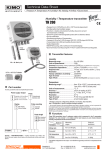
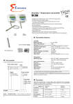
Dimensions
Functions (optional)
240 mm
Voie 1
Voie 2
Voie 3
CPA 300 has 2 analogue outputs which correspond to the first 2 parameters displayed.
You can activate 1 or 2 outputs, and for each output, you can choose between pressure,
air velocity and airflow (optional functions).
Features
120 mm
Functions
Air velocity*
Measuring ranges
2 to 100 m/s (depends on SPI board)
3
CPA
20 mm
Airflow*
0 to 100 000 m /h
(depends on air velocity and duct dimensions)
Units and resolutions
0,1 m/s - 0,1 fpm
1 m3/h - 0,1 m3/s
0,1 l/s - 1 cfm
CPA 300 can display up to 4 parameters simultaneously. The last 2 parameters are
only displayed, they have no output.
87 mm
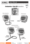
* Differential probe (Pitot tube, Debimo blade...) sold separately.
60 mm
Display features
32 mm
48 mm
Display ......................................electroluminescent alphanumeric (75 x 190 mm)
...................................................protection screen made of inactinic red PMMA
1st line (measurement) .............5 digits (dot matrix 5 x 7) 50 x 190 mm
2nd line (unit)..............................4 digits (14 segments) 13 x 45 mm
Number of channels ................from 1 to 4 channels alternatively (each 3 sec)
Location of channels ...............with 3 red identified LED
Response time .........................< 1 sec.
Housing features
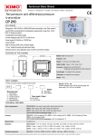
SPI system features
Interchangeable Pressure Sensor
SPI board (Interchangeable Pressure Probe) includes a piezoresistive
sensitive element with its digital electronic system.This system is
individually adjusted and records all the calibration parameters.
Via the automatic recognition by the transmitter, this digital board is
totally interchangeable. Maintenance, service and calibration are
easily performed on site, with no need to stop the process.
Configurable intermediate and centre zero ranges
Probe ref.
SPI 100
SPI 500
SPI 1000
SPI 10000
Pressure range
-100/+100 Pa
-500/+500 Pa
-1000/+1000 Pa
-10000/+10000 Pa
Air velocity range*
2 to 10 m/s
2 to 22 m/s
2 to 30 m/s
2 to 100 m/s
* Air velocity ranges are given as an indication based on a differential probe DEBIMO
(Cm = 1). They do not take into account temperature compensation.
The minimum configurable range is 10% of the full range.
Overpressure tolerated..........25 000 Pa (CPA 301, CPA 302, CPA 303)
................................................70 000 Pa (CPA 304)
Response time .......................1/e (63%) 0,3 sec
Type ........................................digital
Dimensions ............................L = 60 mm, l = 25 mm
Working temperature ............0 to +50°C
Storage temperature .............-10 to +70°C
Air velocity/airflow functions (optional)
Pressure transmitters working with a differential probe (such as débimo, Pitot
tube, orifice plate…) can be configured with a square root function.
Via this function, and from the differential pressure, the transmitter can calculate
air velocity and/or airflow in a duct.
Pitot tubes (with or
without temperature
compensation)
Housing ........................................multi-directional (30°) made of ABS
Protection.....................................IP 63
Fire-proof classification..............V-0 as per UL 94
Dimensions ..................................see drawing
Connection gland ........................polyamide for cable 7 mm max.
Fittings .........................................barbed fittings Ø 6,2 mm
Weight ..........................................1000 g
Technical Specifications
Power supply .............................24 Vac/Vdc ± 10%
230 Vac ± 10%, 50-60 Hz
Output .........................................2 x 4-20 mA or 2 x 0-10 V (4 wires)
.....................................................maximum load : 500 Ohms (4-20 mA)
.....................................................minimum load : 1 K Ohms (0-10 V)
Galvanic isolation ......................on outputs
Consumption..............................5 VA
Relay ...........................................for Ref. CPA300 :
4 6A/230 Vac RCR relays
for Ref. CPA300 HV :
2 6A/230 Vac RCR relays
Audible alarms ...........................buzzer (80 dB)
Electro-magnetical compatibility ...EN 61 326
Electrical connection ..................screw terminal block for cables
Ø 1.5 mm² max
RS 485 communication .............digital : Modbus RTU system
.....................................................communication speed configurable
....................................................from 2400 to 115200 Bauds
RS 232 communication .............digital : ASCII, proprietary protocol
Working temperature.................0 to +50°C
Storage temperature..................-10 to +70°C
Environment...............................air and neutral gases
Relays and Alarms
CPA 300 has 4 stand-alone and configuration alarms :
4 RCR relays (contacts).
CPA 300 HV has 2 stand-alone and configuration alarms :
2 RCR relays (contacts).
You can set :
- the parameter (pressure, air velocity, temperature…)
- 1 or 2 setpoints (up & down) for each alarm
- the time-delay / from 0 to 60 sec.
- the relay operation mode : positive or negative security
- the audible alarm (buzzer) activation.
Self calibration
Air velocity calculation function :
Air velocity (m/s) = CM x CC x CT x D
Pressure (Pa)
CM : cœfficient of the differential probe
CC : coefficient to adap the measuring system to the specifications of
your air movement conditions
CT : temperature compensation coefficient, with the formula below.
574,2 x temp. (°C) + 156842,77
101325
CT =
Electro-valve lifetime ..........................100-million cycles
Benefit .................................................no zero drift
Self calibration frequency .................can be disabled or
set between 1 to 60 min.
Integration of pressure measurement
Airflow calculation function :
3
Thanks to the temperature compensation of the gain (from 0 to 50°C) and to the
self calibration, CPA 300 guarantees an excellent long-term stability, along with a
great measurement accuracy.
Self calibration principle : the microprocessor drives an electro-valve that
compensates for any long-term drift of the sensitive element.
Compensation is made by regular automatic adjustment of the zero. True
differential pressure measurement is then made regardless of the environment
conditions of the transmitter.
2
Airflow (m /h) = air velocity (m/s) x surface (m ) x 3600
Surface : setting of duct type (rectangular or circular) and duct
dimensions (in mm or in inch).
The pressure measurement element is very sensitive and reacts to pressure
changes. When making measurements in unstable air movement conditions, the
pressure measurement may fluctuate. The integration coefficient (from 0 to 9)
makes an average of the measurements; this helps to avoid any excessive
variations and guarantees a stable measurement.
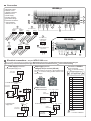
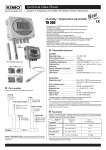
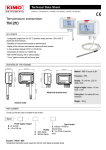
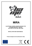
Connection
CPA 300 type
a. Analogue outputs
b. Relays 1 and 2
c. RS 485 connection
d. Relays 3 and 4
e. Power supply
f. RS 232 connector
g. Connection fittings
h. Pressure connections
i. Output selection
4-20 mA or 0-10V
i
e
d
c
a
b
a
Relay 1
g
Relay 2
e
ge
ag
lta
d
olt
.vo ound t
..v roun t
.
.
.
.
.
.
r
n
..
n
..
g
.... ......g urre
.... ....... curre
.
.
.
.
.
.
..
..
..
en
en
...
...
..c
.... ....... .......
op
op
.... ....... .......
V
V
. ....
lly
lly
.. .....
.
0
.
0
.
a
a
.
d
.
1
.
ed
e
0- D.. A ...
0-1 D... A ....
orm on los
orm on los
...n omm lly c
...n omm lly c
GN 0 m
GN 0 m
.
.
c
NO M . orma
NO M . c orma
4-2
4-2
CO .....n
CO .....n
C
NC
N
c
{
e
CPA 300 HV type
For 24 Vdc power
supply models
d
i
c
{
B A
- +
Relay 4
Relay 3
RS485
(Modbus)
_
or
+
a
b
For 24 Vac or 230 Vac power
supply models
en
en
op
op
lly
lly
a
d
a
d
n
rm
se
n
rm
se
no mo lo
no mo lo
.... com ally c
.... com ally c
NO M . orm
NO M . orm
CO .....n
CO .....n
C
NC
N
f
h
{
{
Analogue
output 2
Analogue
output 1
-
+
b
-
+
h
~
N
~
L
f
g
e
.
Electrical connections - as per NFC15-100 norm
!
This connection must be made by a qualified technician. Whilst making the connexion, the transmitter must not be energized. Before making the
connection, you must first check the power supply which is indicated on the transmitter board (see i on the connection drawing)
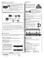
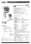
Output signal selection
voltage (0-10 V) or current (4-20 mA)
Power supply connection :
• For 24 Vdc power supply models :
The switch located on the left top of the transmitter board
(see i on connection drawing) enables selection of the
required outputs.
-
+
Power supply
terminal block
24 Vdc
power supply
Down
Up
0-10 V
4-20 mA
+
~ ~
15 14 13 12 11 10 9
230 Vac
N
N
L
L
24 Vac
230 Vac
power supply
4
B-
(RS 485)
A+
(RS 485)
*
0-10 V GND 4-20 mA
-
Regulator display
or PLC/BMS
passive type
+
• 0-10 V voltage output :
Output
terminal block
Regulator display
or PLC/BMS
passive type
+
-
7
NC
*
8
NC
*
9
RX
(RS 232)
10
NC
*
11
TX
(RS 232)
12
NC
*
0-10 V GND 4-20 mA
13
NC
*
14
NC
*
15
GND (RS 232)
+
Power supply
terminal block
*
*
-
Ground
Live
Neutral
NC
NC
NC
Power supply
• For 230 Vac power
supply models :
2
3
5
G
Power supply
Class II
*
6
+
24 Vac
~
NC
• 4-20 mA current output :
Output
terminal block
~
4 3 2 1
Output connexion :
or
G
L
L
-
or
N
230 Vac
8 7 6 5
1
Vac Vac
N
RS 232 and RS 485
(see f on connection drawing)
Pin # Description
• For 24 Vac power supply models :
Power supply
terminal block
Connection of SUB-D15
! Caution :
NC * --> DO NOT CONNECT
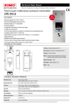
Calibration
Numerical communication
RS 232 communication
On-site adjusting and calibration:
The professional configuration interface,
with a dynamic pressure calibration
bench, enables you to adjust and
calibrate your transmitters directly on
site or in laboratories.
Output diagnostics:
With this function, you can check with a
multimeter (or on a regulator/display, or on
a PLC/BMS) if the transmitter outputs work
properly. The transmitter generates a
voltage of 0 V, 5 V and 10 V or a current of
4 mA, 12 mA and 20 mA .
Modbus network (RS 485 system)
Certificate :
• CPA 300 is supplied with adjusting certificate. Calibration
certificate is offered as an option.
• SPI sensitive elements (interchangeable pressure probes) are
supplied with adjusting certificates.
RS 232
RS 485
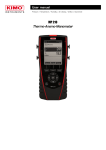
Mounting
• RS 485 digital communication is a 2-wire network, on which the transmitters are
connected in parallel. They are connected to a PLC/BMS via the RTU Modbus
communication system. In the same way as CPA 300 is configured with remote control,
Modbus system enables to configure at distance: activate/deactivate a channel, set the
measuring range of analogue outputs.
48.5 mm
14
• When a Class 200 or 300 transmitter is connected to CPA 300 (via RS 232), all the
measurements can be sent to the PLC/BMS via the RS 485, with only one address.
R
• Via CPA 300, you can set up a network of transmitters/displays, on a RS 485 home
bus (new or existing network).
With the 2 screws, install the mounting bracket in horizontal position
along a plane wall (see below dimensions / drilling drawing).
Put the display inside the mounting bracket,
mm
with the 2 screws.
Ø7
Remove the screw covers located on the
right and left side of housing, in order to
have access to the 4 shutting screws. Make
the electrical connection with the
connection glands, with soft cable Ø 7 mm
maximum. Close the housing before
powering on.
240 mm int.
150 mm
46.5 mm
Configuration
You can configure all the parameters : units, measuring ranges, alarms,
outputs, channels … via the different methods shown below :
Via remote control (optional)
This is convenient in order to configure the transmitters located far from the user
or hard to reach. Same way as with a keypad (see user manual).
Via software (optional)
Simple and user-friendly configuration. See LCC 300 user manual.
Configurable analogue outputs
Range with centre zero (-50/0/+50 Pa), with
offset zero (-30/0/+70 Pa) or standard range
(0 /+100 Pa) => you can configure your own
intermediate ranges according to your needs,
between 10% and 100% of the full scale. The
minimum configurable range is 10% of the full
scale.
-100
Range
0
-100
www.kimo.fr
EXPORT DEPARTMENT
Tel : + 33. 1. 60. 06. 69. 25 - Fax : + 33. 1. 60. 06. 69. 29
e-mail : [email protected]
Options
10V
20 mA
New range
0
0V
4 mA
50
mm
Maintenance
+100
(Pa, mmH2O...)
0V
4 mA
Ø5
Avoid aggressive solvents.
Protect the transmitter and probes from any cleaning product
containing formol, which may be used for cleaning rooms or
ducts.
Via Modbus (optional)
Configuration of all parameters from your PC, via the supervision or data
acquisition software.
Configure the range according to your
needs : outputs are automatically
adjusted to the new measuring ranges.
46.5 mm
19mm
5 mm
+100
(Pa, mmH2O...)
SQR/2 function (square root extraction for air velocity
and airflow calculation)
Digital output for Modbus network (RS 485 system)
LCC 300 configuration software with RS 232 connection
cable
Infrared remote control for configuration
Calibration certificate
Transmitter resolution at 0.1 Pa (CPA 301)
Optional accessories
Pitot tubes
Debimo measuring blades
Mounting brackets
Sliding fittings
10V
20 mA
Distributed by :
Connection gland
Clear tube
Through-connections
Pressure connections
32 mm
RS 232
Ref. FT ang - CPA300 - 08/09 F - RCS (24) Périgueux 349 282 095 Non-contractual document - We reserve the right to modify the characteristics of our products without prior notice.
• Via the RS 232 connection, CPA 300 can display 1
or 2 parameters which are measured by other
Class 200 and 300 transmitters.
Benefit : CPA 300 can display (in addition to the
pressure), other parameters such as temperature and
humidity from a TH 200 (for example).
• Via the RS 232 connection, you can also configure your
transmitter with the LCC 300 software.
• RS 232 connection cable is available in 2 m, 5 m or 10 m (maximum) lengths