1
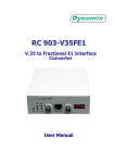
science & technology | inverters | test
The Solar Power Magazine
International
A
96.2 % at high irradiation
9/2010
www.photon-international.com
The Solar Power Magazine
Fronius submitted a device from its first
transformerless inverter series to PHOTON
Laboratory for testing – and the IG TL
5.0 made a very good impression
International
F
A
95.9 % at medium irradiation*
9/2010
www.photon-international.com
* when measured with increasing DC powers (see MPPT adjustment
efficiency section), the PHOTON efficiency was 95.7 percent, but that
also suffices for an A grade
Highlights
• The IG TL 5.0 is a transformerless
inverter with a DC nominal power of
4,730 W
• The MPP range stretches from 350 to
700 V
• The unit’s maximum conversion efficiency comes in at 98 percent; the
European efficiency is 97.4 percent,
while the Californian efficiency is 97.5
percent
• The PHOTON efficiency is 95.9 percent at medium irradiation with decreasing DC power, but 95.7 percent
with increasing DC power; it hits 96.2
percent at high irradiation
• The unit’s IP 55 protection type, and
low dependence on operational and
ambient temperatures allow for installation in a variety of locations
156
A successful debut
ronius International GmbH, based in
Wels, Austria, presented its first transformerless inverter at the European Intersolar
trade fair in June 2009. Then, after 6 months,
four devices from the company’s IG TL series finally hit the market. The company attributes the delay to the inverters being in a
»test phase.« However, it seems more likely
that Fronius, like all inverter manufacturers
at that point, was suffering from supply issues for important components. The IG TL
5.0, which PHOTON Laboratory received in
March after Fronius completed the usual test
agreement, was definitely one of the first of
its kind to hit the lab’s test bench.
While this device marks Fronius’ entry
into the ranks of manufacturers offering
transformerless devices, the IG TL series
is host to a number of other innovations as
well. The device is divided into two separate
parts: the front unit with the power electronics can be removed from the rear section without dismantling the AC and DC
connections – hardly a conventional design.
Furthermore, the datasheet promises excellent performance, which naturally piqued
curiosity at PHOTON Lab about how well
this newcomer would perform during tests.
Construction
The IG TL series consists of the IG TL
5.0 with 4,600 W of AC nominal power, the
IG TL 3.0 with 3,000 W, the IG TL 3.6 with
3,600 W, and the IG TL 4.0 with 4,000 W. All
four models in the range are transformerless, and are identical in terms of construction, dimensions and weight.
The test candidate has a well-arranged
construction and appears simple to manufacture. The first thing installers are likely
to notice is the unusual concept for attaching the unit to the wall and hooking the
unit up electrically: the wall bracket has an
integrated connection area with terminal
blocks. The connectors that attach to the
blocks are located on the bottom of the power element’s box. Therefore, when installing
the unit, first the wall bracket is installed,
and then the connectors are attached to the
clamps integrated in the bracket. The actual
inverter is located in a box that is inserted
onto the wall bracket via four tracks, and
then latched into the terminal blocks. Finally, the two separate pieces are secured
together using six screws. The goal of this
construction is to facilitate service and
maintenance. For most repairs, the device’s
core can be removed from the bracket and
replaced with a substitute (for instance, a
device with a new circuit board).
The box with the device’s central unit has
its own cover. Once removed, the inside of
the inverter is on display. At the bottom, a
filter circuit board holds the power connections, the DC- and AC-side EMI filters, as
International September 2010
90
90
83
83
76
76
68
62.8
57.8
68
62.8
60
57.8
60
52
52
44
photon-pictures.com (3)
44
36
36
28
28
20
20
The rear section of the IG TL 5.0, which is attached to the wall, contains the connectors and a slot for the communications circuit board. The box with the actual inverter
is then inserted into this section. Thermographic images showed no problematic temperatures.
well as six string fuses. The power circuit
board, which also contains the control unit,
is located on a higher level and is connected
to the filter circuit board. Soldered underneath the power circuit board is a transistor module, the heat losses from which are
directed away via a small cooling element
situated below the box. The buck converter’s
and the sinusoidal filter’s chokes are located
above the power element circuit board cast
in a cartridge inside the box. There is a
small, DC-powered fan for distributing heat
inside the box on the same level as the circuit boards. A DC circuit breaker is mounted
at the bottom of the device, on the unit that
attaches to the wall. There is also a plug-in
box for the communications circuit board.
The housing therefore consists of three
pieces: the wall bracket, the central unit
made of molded plastic and the cover made
of aluminum sheeting. The device has an IP
55 protection type and is therefore suitable
for installation outdoors, if protected from
the elements.
Both the small internal fan and the cooling element fan are easy to remove or exchange in the event of a malfunction. The
cooling element fan is subjected to surrounding conditions and can therefore clog
if operated in a dirty location.
In total, six string cables and three grid
cables are fed into the housing and directly
attached to the terminal block. All of the
International September 2010
cables are internally strain-relieved.
To ensure safe operation, the unit offers
grid monitoring with all-pole-sensitive residual current protection and DC-side insulation monitoring, according to the German DIN VDE 0126-1-1 norm. The grid is
checked for correct impedance, voltage, frequency, and an appropriate DC share in the
AC current, while residual-current monitoring is carried out based on absolute values
and changes in amplitude. An insulation test
on the solar generator, which occurs prior
to each connection to the grid, checks the
resistance between the generator’s connections and the ground. An unusual feature
of the IG TL inverter is that it continually
aligns and analyzes the current of attached
strings.
The electrolytic capacitors in the power
element have a temperature class of 105 °C
and are therefore well-designed to handle
ambient temperatures. The device’s status is
shown with a display and three LEDs. The
inverter is equipped with one USB port, a 12
V signal output, as well as a Solar Net input and output. Software updates are easy to
install: a new version can simply be downloaded from Fronius’ website onto a USB
stick and then transferred to the device via
the USB port. The Solar Net connections are
used to integrate the unit into Fronius’ Datcom system, for instance, to communicate
with additional inverters, or irradiation and
temperature sensors. The 12 V signal output (normally open contact) is available for
connecting audible alarms, visual signals or
installation relays.
Operation
The device arrives at the customer’s home
well packaged and protected in two Styrofoam molds. Mounting the wall bracket,
which contains the connection area, and inserting the power element is simple enough.
At 19.1 kg, the IG TL 5.0 is rather light.
As long as the solar generator is properly
designed and the internal DC disconnect is
switched on, the inverter can begin operation. It took about 52 seconds to run a series
of tests before connecting to the grid.
The display is level with the front cover,
has orange backlighting and is easy to read.
The menu language is available in German
or English, and the addition of other languages is planned. The display is activated
as soon as grid voltage is present and turns
off if the device isn’t used for 2 minutes.
In the set-up menu, users have the option
of setting the display lighting to turn on or
off for extended periods of time. The unit’s
four buttons can be used to set a variety of
parameters.
The display offers access to a lot of data
and is clearly structured. In addition to
various status and error messages, the unit’s
157
science & technology | inverters | test
=
=
sjmm=áå=s
At different input powers – beginning with
the highest values and decreasing to the
lowest possible values – the IG TL 5.0
reaches a consistent adjustment efficiency of above 99 percent.
= Overall efficiency
sjmm=áå=s
The MPP tracker’s consistent operation
(with decreasing DC power) results in an
overall efficiency path that is almost identical to that of conversion efficiency, though
at a slightly lower level.
OM
PM
ηpìã=áå=B
NMM
VR
VM
UR
UM
TR
TM
NM
OM
PM
TMM
SUO
SSP
SQR
SOS
SMU
RUV
RTN
RRP
RPQ
VR
RNS
QVT
QTV
VS
QSN
QQO
QOQ
VT
QMR
PUT
PSU
PRM
NM
OM
PM
QM
RM
SM
TM
UM
B=kçãáå~ä=éçïÉê=EmjmmF
VM
NMM
NNM
B
NMM
VU
VS
VQ
VO
VM
UU
US
UQ
UO
UM
TU
TS
TQ
TO
TM
M
NOM
s
NIMMM
=
UMM
SMM
QMM
=
TMM
SUO
SSP
SQR
SOS
SMU
RUV
RTN
RRP
RPQ VV
RNS
QVT
QTV
QSN
QQO
QOQ
QMR
PUT
PSU
PRM
NM
QM
RM
SM
TM
UM
VM
NMM
NNM
NOM
OMM
M
M
O
Q
S
=
QM
RM
SM
TM
UM
B=kçãáå~ä=éçïÉê=EmjmmF
VM
NMM
NNM
U NM NO ât
TMM
SUO
SSP
SQR
SOS
SMU
RUV
RTN
RRP
RPQ
RNS
QVT
QTV
QSN
QQO
QOQ
QMR
PUT
PSU
PRM
NOM
TM TR UM UR VM VR NMM
ηpìã=áå=B
=
× MPPT adjustment efficiency
(decreasing power)
158
=
sjmm=áå=s
The IG TL 5.0 reaches its highest value at
lower MPP voltages; beyond around 424 V,
the buck converter is activated, resulting
in losses in efficiency.
η áå=B
s
NIMMM
NMM
VR
UMM
VM
SMM
UR
QMM
UM
aáÉëÉå=qÉñí=ìåÇ=ÇÉå=o~ÜãÉå=ê~ìëåÉÜãÉåK=aÉê=o~ÜãÉå=áëí=NNIQ=Åã=ÄêÉáíI=~äëç=ëç=ÄêÉáí=ïáÉ=ÇáÉ
OMM
TR
O=pé~äíÉå=áã=eÉÑí=ìåÇ=áå=ÇáÉëÉê=dê∏≈É=ëçää=Ç~ë=aá~Öê~ãã=~ÄÖÉÇêìÅâíI=~äëç=Ç~ë=aá~Öê~ãã=åáÅÜí=òççãÉå
M
TM
M O Q S U NM NO ât
NM
OM
PM
QM
RM
SM
TM
UM
VM NMM NNM NOM
B
TMM
TMM
NMM
SUO
SUO
VU
SSP
SSP
VS
SQR
SQR
VQ
SOS
SOS
SMU
SMU
VO
RUV
RUV
VM
RTN
RTN
UU
RRP
RRP
RPQ
US
RPQ
VR
RNS
RNS
UQ
QVT
QVT
UO
QTV
QTV
VS
UM
QSN
QSN
QQO
QQO
TU
QOQ
QOQ
TS
VT
QMR
QMR
TQ
PUT
PUT
TO
PSU
PSU
PRM
PRM
TM
NM
OM
PM
QM
RM
SM
TM
UM
VM NMM NNM NOM
TM TR UM UR VM VR NMM
M
η áå=B
B=kçãáå~ä=éçïÉê=EmjmmF
=
Conversion efficiency
B
NMM
VU
VS
VQ
VO
VM
UU
US
UQ
UO
UM
TU
TS
TQ
TO
TM
M
International September 2010
sjmm=áå=s
TMM
SUO
SSP
SQR
SOS
SMU
RUV
RTN
RRP
RPQ
RNS
QVT
QTV
QSN
QQO
QOQ
QMR
PUT
PSU
PRM
B
NMM
VU
VS
VQ
VO
VM
UU
US
UQ
UO
UM
TU
TS
TQ
TO
TM
M
VV
VU
NM
OM
PM
QM
RM
SM
TM
UM
B=kçãáå~ä=éçïÉê=EmjmmF
»present« mode shows the following values:
fed-in power, grid voltage, output current,
grid frequency, and generator voltage and
current. Using a Fronius Sensor Box, users
can also access data on module temperature,
ambient temperature and irradiation values.
The time and date are also displayed.
The device also has a »today« mode, in
which the display informs users about oper-
VM
NMM
NNM
NOM
ating duration, fed-in energy, the monetary
value of the achieved yield – whereby the tariff level is entered by the operator, choosing
the applicable currency from over 20 different countries available worldwide – and an
estimated value for CO2 savings, as well as
the maximum value for output power, grid
voltage and generator voltage. In conjunction with the Sensor Box, users can access
MPPT adjustment efficiency
(increasing power)
If different power values are applied, progressing from low to high powers, the IG
TL 5.0’s MPP tracking precision decreases,
particularly at lower powers and voltages.
This causes the PHOTON efficiency to decrease slightly.
data on the maximum and minimum values
for module and ambient temperatures, as
well as the maximum irradiation value.
Instruction manual
The device also includes a very comprehensive and informative user’s manual. It
applies to all units in the IG TL range. In ad-
Qinhuangdao Donwoo Electronic Co.,Ltd,
which registered for setting
up in 2005, is the specialization company on manufacture the welding
ribbon of the Solar PV modules.
The engineers of Donwoo are all the
experts in the field of PV product production&application.
Profession
& engrossment ensure the product quality.
PV ribbon wire, bus-bar wire with vacuum packing.
Offer advanced technology and rich experience on products.
Provide good quality and large amount production.
Add.:
No.24, Xihuan North Road, Economic and Technological
Development Zone, Qin Huangdao
Phone: 86-335-5311568
Fax: 86-335-5311817
E-mail: [email protected]
Web:
http://www.pv-ribbon.com
ABS cylinder
Vacuum-packed
International September 2010
Paper box for cut off
Vacuum-packed
Paper disk
Vacuum-packed
159
science & technology | inverters | test
Weighted conversion efficiency
tÉáÖÜíÉÇ=ÅçåîÉêëáçå=ÉÑÑáÅáÉåÅó=ηbìêçI=η`b`=áå=B
NMM
ηbìêç=ã~åìÑ~ÅíìêÉê=ëéÉÅáÑáÉÇ=Z=VTKP=B
VU
The European efficiency is almost as high
as the Californian efficiency over the entire
MPP voltage range. The use of a buck converter results in a considerable decrease
in efficiency.
VS
VQ
VO
VM
UU
US
UQ
UO
UM
=bìêçéÉ~å=ïÉáÖÜíÉÇ
==ηbìêçj~ñ=Z=VTKQ=B
TU
=`~äáÑçêåá~å=ïÉáÖÜíÉÇ
==η`b`j~ñ==Z=VTKR=B
TS
TQ
TO
TM
Overall efficiency
at different VMPP voltages
PRM
PSU
PUT
QMR
QOQ
QQO
QSN
QTV
QVT
lîÉê~ää=ÉÑÑáÅáÉåÅó=ηpìã=áå=B
NMM
RNS RPQ
sjmm=áå=s
RRP
RTN
RUV
SMU
SOS
SQR
SSP
SUO
TMM
ηpìãj~ñ
VU
VS
The IG TL 5.0 appears to be more comfortable at low voltages. However, efficiency
develops as it should at all voltage levels:
increasing steeply at the start, then remaining at a constant level (shown here when
measured at decreasing powers).
VQ
VO
VM
UU
US
UQ
UO
UM
==sjmm=Z=PRMKM=s=EsjmmãáåF
TU
==sjmm=Z=TMMKM=s=Esjmmã~ñF
==^îÉê~ÖÉ=çîÉê~ää=ÉÑÑáÅáÉåÅó
TS
ηpìãj~ñ=Z=VTKVT=B
ηpìãj~ñ=Z=VRKVM=B
=η^îÖpìãj~ñ Z=VSKRQ=B
ηmãÉÇ Z=VRKV=BI=ηmÜáÖÜ Z=VSKO=B
TQ
TO
TM
Accuracy of inverter display
=
The Fronius inverter’s display is highly accurate.
160
R
NM
NR
OM
OR
PM
PR
QM
QR
RM RR SM SR TM TR
B=kçãáå~ä=éçïÉê=EmjmmF
UM
UR
VM
VR NMM NMR NNM NNR NOM
aÉîá~íáçå=áå=B
PM
OU
OS
OQ
OO
OM
NU
NS
NQ
NO
NM
U
S
Q
O
M
JO
JQ
JS
JU
JNM
JNO
JNQ
JNS
JNU
JOM
JOO
JOQ
JOS
JOU
JPM
R NM NR
OM
OR
PM
PR
QM
QR
RM RR SM SR TM TR
B=kçãáå~ä=éçïÉê=EmjmmF
UM
UR
VM
VR NMM NMR NNM NNR NOM
International September 2010
science & technology | inverters | test
Manufacturer’s response
The efficiency measurements match
our own results. Measurements in our
lab and examinations at AIT (previously
Arsenal Research) did not detect the
changes in MPP tracking behavior at
very low powers. We will examine and
analyze these test results in greater
detail.
dition to technical data and general information, it contains descriptions of installation,
implementation and operating the inverter,
as well as instructions on troubleshooting
and maintenance.
The user’s manual can also be downloaded from the manufacturer’s website
in the following languages: Czech, Dutch,
English, French, German, Italian, Slovakian
and Spanish. The technical datasheet is also
available in Greek and Portuguese.
Circuit design
The IG TL 5.0 has a two-stage topology, is
transformerless and has one MPP tracker for
all of the strings. First, energy from the PV
generator reaches a buck converter, serving
as a DC/DC converter, via an EMI filter. The
buck converter reduces the input voltage to
a DC voltage of 440 V at most and feeds the
voltage into an intermediate circuit, which
is connected to the output bridge. In an
MPP voltage range of 350 to 440 V, the buck
converter is by-passed by a relay, which, depending on the power, results in a conversion efficiency around 0.7 to 1.4 percentage
points higher. Via a subsequent output filter,
the output bridge feeds pulse-width modulated sinusoidal voltage into the grid. All of
the power semiconductors are located in a
semiconductor module.
A subsequent automatic disconnection
unit, made of four AC output relays (two
connected in series for both the neutral
and live wires) separates the inverter from
the grid in the event that grid voltage, grid
frequency or grid impedance deviate from
designated limits. The same applies in the
event that residual current is measured on
the DC side or grid side. An output filter,
installed by the grid clamp, eliminates any
radio interference.
Measurements
All of the following measurements are
based on a grid voltage of 230 V. The IG TL
5.0’s maximum DC voltage is 850 V and the
DC nominal power is 4,730 W. At most, the
inverter can accept a generator power of
5,250 W.
Depending on whether the DC power is
preset to increase or decease, the device
displays different behavior in terms of MPP
tracking. The differences are small, but significant, and also have an impact on the
PHOTON efficiency. Therefore, both cases
are documented in this overview.
Locating the MPP: At the start of the
measurements, the DC and AC sides were
switched off. At a predetermined IV curve
with nominal power and an MPP voltage of
515 V, the inverter needs about 52 seconds
to connect to the grid, and then another 53
seconds to reach its MPP. When switching
162
from 515 V to 497 V, the device needs about
61 seconds, while switching to the next
higher MPP voltage of 533 V takes about 77
seconds.
MPP range: The MPP range stretches
from 350 to 700 V, which is a wide range.
The distance between the upper limit and
the unit’s maximum DC voltage of 850 V is
not quite adequate enough.
Conversion efficiency: The inverter
can operate with 110 percent of its nominal
power in an MPP voltage range of 350 to 700
V. Therefore, efficiency was calculated for
this area.
A small area in the diagram with hatching
going from the bottom left to the top right
represents limitations on the MPP voltage
range when the device is used with crystalline modules; the area with hatching in the
opposite direction reveals limitations on the
device when used with thin-film modules,
due to the inadequate distance between the
maximum MPP voltage and maximum DC
voltage.
The area of maximum efficiency forms a
plateau within a power range of 25 to 105
percent and up to an MPP voltage range of
424 V. At higher voltages, the buck converter
is activated, meaning conversion efficiency
drops by 0.7 to 1.4 percentage points.
The vertical line at 60 percent of nominal power and the horizontal line at an MPP
voltage of 350 V meet at the unit’s maximum
efficiency of 98 percent. Therefore, PHOTON Lab’s measurements exceed the manufacturer’s specification of a maximum efficiency of 97.7 percent considerably. At high
MPP voltages, maximum conversion efficiency decreases by around 2.1 percentage
points. At low powers, below 15 percent of
nominal power, efficiency decreases by 5 to
8 percentage points. The power factor cos ϕ
at nominal power was about one.
MPPT adjustment efficiency: The
MPPT adjustment efficiency is consistent
and high over the entire operating range, if
measured when power is set to decrease. A
slight exception is recorded at low powers
and MPP voltages due to the buck converter. Otherwise, the inverter’s MPP power is
consistently above 99 percent of available
power.
If power is set to increase, the MPPT adjustment efficiency is somewhat less consistent. It drops at low powers when the
buck converter comes into play, as well as
at higher voltages. Otherwise, the values are
consistently above 99 percent here, too.
Overall efficiency: The area of maximum overall efficiency is found at low MPP
voltages. The vertical line at 60 percent of
nominal power and the horizontal line at
an MPP voltage of 350 V – so at the lower
edge of the MPP voltage range – meet at the
maximum overall efficiency of 98 percent.
Weighted conversion efficiency: EuroInternational September 2010
science & technology | inverters | test
pean efficiency reaches its peak at low MPP
voltages. At 97.4 percent, it exceeded the
manufacturer’s specifications of 97.3 percent. The difference between the maximum
conversion efficiency and maximum European efficiency is just 0.6 percentage points.
Californian efficiency reaches its peak at
97.5 percent, with the highest values also
occurring at low MPP voltages. The diagram
clearly shows that efficiency drops when the
buck converter is activated.
Course of overall efficiencies, average
overall efficiency and PHOTON efficiency: The PHOTON efficiency at medium irradiation and simulated decreasing DC power
is 95.9 percent; at high irradiation, it reaches
96.2 percent. When simulating an increase
in DC power, the PHOTON efficiency for
medium irradiation is 0.2 percentage points
lower at 95.7 percent.
Feed-in at nominal power: The inverter
feeds in 100 percent of its nominal power
over an input voltage range of 350 to 700 V
at an ambient temperature of 25 °C.
Displayed output power: If the test candidate is fed with different powers between
5 and 110 percent of nominal power at a
constant MPP voltage of 515 V, so in the medium range, there are only slight deviations
between the values displayed by the inverter
and those taken by a power analyzer over the
entire power range. The difference fluctuates between +0.7 and -1.4 percent. Therefore, the display’s accuracy is equivalent to
that of a class B meter (formerly known as
precision class 1).
In this context, the user’s manual notes
that the inverter’s measuring device is not
calibrated and that slight deviations up to
a few percentage points can occur. That
kind of admission is one that PHOTON Lab
would like to see other manufacturers make,
since a lot of devices are considerably less
accurate than the IG TL 5.0.
Operation at high temperatures: The
manufacturer specifies a wide temperature
range of -20 to 55 °C. Together with its IP
55 protection type, that means the unit can
be installed in either very cold or very warm
locations, for instance, under a roof or outdoors. There are no temperature-related
power reductions to take into consideration
when the ambient temperature increases
– Fronius’ inverter feeds 100 percent of its
nominal power into the grid until around
55.3 °C. At that point, the device reduces its
power and efficiency falls, but only by about
0.4 percentage points. The selected operating point was 4,730 W of DC power and an
MPP voltage of 515 V.
Overload behavior: If the IG TL 5.0 is offered an overload of 1.3 times its nominal
input power, so 6,149 W, at an MPP voltage
of 515 V and an ambient temperature of 27
°C, the unit limits its power to around 5,245
W, which is 10.9 percent above the DC nom164
inal power of 4,730 W. Thus, the device’s
overload range is quite large. When power
limitations take effect, the unit pushes the
operating point toward higher input voltages. The DC voltage adjusts itself to a value
of around 568 V.
Own consumption and night consumption: The inverter’s own consumption in its
tested construction is up to 8 W on the AC
side and 2.6 W on the DC side. The manufacturer makes no specifications here. At
night, the inverter consumes around 0.3 W
of real power from the grid. The manufacturer specifies 0.2 W.
Thermography: Thermographic images show the inverter from above while
operating at nominal power at an ambient
temperature of 26 °C. However, the unit’s
multi-level construction makes it impossible to measure the temperatures for all components. Component temperatures as high
as 62.8 °C were seen on the circuit board.
These values aren’t exactly low, but within
reasonable limits for power electronics. The
temperature of the electrolytic capacitors in
the power element is in a safe range.
Summary
The Fronius IG TL 5.0 is clearly arranged
and appears simple to manufacture. The
system employed with the wall bracket and
power connections is unusual, and – as with
most unconventional solutions – it remains
to be seen whether it will prove itself in
practice.
The maximum conversion efficiency of 98
percent is a very high value, but only occurs
at the lowest possible voltages. The device
reaches its highest conversion efficiency
at MPP voltages of between 350 and 424
V, that is, when the buck converter, which
functions as a DC/DC converter, is bypassed
by a relay. At low powers, the conversion efficiency drops by 5 to 8 percentage points;
at higher MPP voltages it drops by up to 2.1
percentage points.
The European efficiency deviates from
the maximum conversion efficiency by 0.6
percentage points. Thanks to its very consistent and high MPPT adjustment efficiency,
the graph for overall efficiency is almost
identical to that of conversion efficiency.
The MPP voltage range of 350 to 700 V
specified by the manufacturer is not quite
far enough removed from the inverter’s
maximum DC voltage of 850 V. Assuming a
fill factor of 75 percent, it can be exploited
up to 680 V for crystalline modules and 629
V for thin-film modules.
If decreasing DC power is simulated, the
PHOTON efficiency for medium irradiation
is very high at 95.9 percent. The difference
of around 2.1 percentage points between the
maximum conversion efficiency and PHOTON efficiency reflects the rather consider-
able dependence on voltage and power. The
PHOTON efficiency for high irradiation is
slightly higher, at 96.2 percent.
If increasing DC power is simulated, the
MPPT adjustment efficiency drops at low
powers. As a result, the PHOTON efficiency
at medium irradiation decreases slightly to
95.7 percent. The manufacturer states that
it is currently analyzing this situation (see
box, p. 162). The PHOTON efficiency for
high irradiation with increasing DC power
was identical to the value seen with decreasing power.
When selecting the PV system’s MPP, the
lower third of the MPP voltage range should
be chosen. Overall efficiency also reaches its
peak in this range.
The IG TL 5.0 has a large overload range
of 110.9 percent. The inverter’s output power display is accurate over the entire power
range.
The efficiency’s dependence on temperature is low at 0.4 percentage points and the
usable ambient temperature range is fairly
wide at -20 to 55 °C, so there is no need to
take power reductions into account.
This light, easy to operate inverter with a
good PHOTON efficiency is a great addition
to Fronius’ product line. It takes its place in
the top fourth of the inverters that PHOTON
Lab has tested thus far. It is suited for use
with all module types (even thin films) that
don’t need to be grounded. The company is
planning to obtain the corresponding approvals from module manufacturers for its
product.
Text Heinz Neuenstein, Jochen Siemer
Further information
Contacts page 264
International September 2010