1
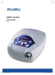
VPAP™ III ST-A
Reorder number: 248107/1 05 02
USER’S MANUAL
English
VPAP™ III ST-A
Reorder number: 248107/1 05 02
USER’S MANUAL
English
Manufactured by:
ResMed Ltd 1 Elizabeth MacArthur Drive Bella Vista NSW 2153 Australia
Tel: +61 (2) 8884 1000 or 1 800 658 189 (toll free) Fax: +61 (2) 8883 3114 Email: [email protected]
Distributed by:
ResMed Corp 14040 Danielson Street Poway CA 92064-6857 USA
Tel: +1 (858) 746-2400 or 1-800-424-0737 (toll free) Fax: +1 (858) 746-2900 Email: [email protected]
ResMed (UK) Limited 65 Milton Park Abingdon Oxfordshire OX14 4RX UK
Tel: +44 (1235) 862 997 Fax: +44 (1235) 831 336 Email: [email protected]
ResMed Asia Pacific Ltd 97 Waterloo Road North Ryde NSW 2113 Australia
Tel: +61 (2) 9886 5000 or 1 800 991 900 (toll free) Fax: +61 (2) 9889 1471 Email: [email protected]
ResMed Finland Niittykatu 6 FIN 02200 ESPOO Suomi
Puh: +358 9 8676820 Faksi: +358 9 86768222 Sähköposti: [email protected]
ResMed GmbH & Co. KG Fraunhoferstraße 16 82152 Martinsried Deutschland
Tel: +49 (0) 89/99 01 - 00 Fax: +49 (0) 89/99 01 - 10 55 Email: [email protected]
ResMed Hong Kong Limited Room 1714, Miramar Tower 132-134 Nathan Road Tsim Sha Tsui Hong Kong
Tel: +852 2366 0707 Fax: +852 2366 4546 Email: [email protected]
ResMed Japan Nihonbashi Hisamatsu Bldg. 4F, 2-28-1 Nihonbashi-Hamacho, Chuo-Ku, Tokyo 103-0007, Japan
Tel: +81 (3) 3662 5056 Fax: +81 (3) 3662 5040
ResMed Malaysia Sdn Bhd Suite E-10-20, Plaza Mon’t Kiara No. 2 Jalan 1/70C Mon’t Kiara 50480 Kuala Lumpur
Malaysia Tel: +60 3 6201 7177 Fax: +60 3 6201 2177 Email: [email protected]
ResMed NZ Ltd PO Box 51-048 Pakuranga Auckland New Zealand
Tel:+64 274 737 633 Fax:+64 9 239 0193 Email: [email protected]
ResMed SA Parc de la Bandonnière 2, rue Maurice Audibert 69800 Saint-Priest France
Tél. : +33 (0) 4 37 251 251 Fax : +33 (0) 4 37 251 260 Email: [email protected]
ResMed Singapore Pte Ltd 238A Thomson Road #12-03/04, Novena Square, Tower A Singapore 307684
Tel: +65 6284 7177 Fax: +65 6284 7787 Email: [email protected]
ResMed Spain SL C/Arturo Soria, 245 28033 Madrid España
Tel: +34 (93) 5908154 Fax: +34 (93) 5908153 Email:[email protected]
ResMed Sweden AB Industrigatan 2 S-461 37 Trollhättan Sverige
Tel: +46 520 420 110 Fax: +46 520 397 15 Email: [email protected]
Labhardt AG Thannerstrasse 57 CH-4054 Basel Schweiz
Tel: +41 (061) 307 9711 Fax: +41 (061) 307 9722 Email: [email protected]
US DESIGNATED AGENT: ResMed Corp
EU AUTHORISED REPRESENTATIVE: ResMed (UK) Ltd
Internet: www.resmed.com
Protected by patents: AU 697652, AU 699726, AU 713679, EP 0661071, US 4944310, US 5199424, US 5522382,
US 6213119, US 6240921, US 6705315. Other patents pending.
Protected by design registrations: AU 147283, AU 147335, AU 147336, CH 128.709, CH 128.710, CH 128.711,
CH 128.712, DE 40201723, DE 40202007, DE 40202008, DE 40202020, ES 153514, ES 153515, ES 153516,
ES 153518, ES 156135, ES 156136, FR 02 1407, GB 3001791, GB 3001819, GB 3001820, GB 3001821, JP 1164087,
JP 1164265, JP 1164266, JP 1164267, SE 75598, SE 75599, SE 75600, SE 75715, US D467335,
US D468011, US D476077, US D477868, US D487311. Other designs pending.
VPAP, Activa, HumidAire, HumidAire 2i, HumidAire 2iC, Mirage, SmartStart, Smart Data, Ultra Mirage and
Vista are trademarks of ResMed Ltd, and VPAP, Activa, HumidAire, HumidAire 2i, HumidAire 2iC, Mirage,
SmartStart, Ultra Mirage and Vista are are Registered in U.S. Patent and Trademark Office.
© 2005 ResMed Ltd.
INTRODUCTION . . . . . . . . . . . . . . . . . . . . . . . . . . . . . . . . . . . . . . . . . . . . 1
DEFINITIONS
USER/OWNER RESPONSIBILITY
1
1
ENGLISH
CONTENTS
MEDICAL INFORMATION . . . . . . . . . . . . . . . . . . . . . . . . . . . . . . . . . . . . . 1
WHAT THE VPAP™ III ST-A IS FOR
CONTRAINDICATIONS
WARNINGS
CAUTIONS
1
1
2
2
THE VPAP III ST-A SYSTEM . . . . . . . . . . . . . . . . . . . . . . . . . . . . . . . . . . . 5
VPAP III ST-A COMPONENTS
MASKS
HUMIDIFIER
ACCESSORIES
5
6
7
7
PREPARING FOR USE . . . . . . . . . . . . . . . . . . . . . . . . . . . . . . . . . . . . . . . . . 9
SETTING UP THE VPAP III ST-A
FEATURES OF THE VPAP III ST-A
9
14
OPERATING INSTRUCTIONS . . . . . . . . . . . . . . . . . . . . . . . . . . . . . . . . . . 21
STARTING TREATMENT
STOPPING TREATMENT
THE ALARMS
USING THE MASK-FITTING FEATURE
USING DC POWER TO RUN THE VPAP III ST-A
HELPFUL HINTS
21
23
23
27
28
28
CLEANING AND MAINTENANCE . . . . . . . . . . . . . . . . . . . . . . . . . . . . . . . 31
DAILY
WEEKLY
PERIODICALLY
REPLACING THE AIR FILTER
SERVICING
31
31
31
32
32
TROUBLESHOOTING . . . . . . . . . . . . . . . . . . . . . . . . . . . . . . . . . . . . . . . .
SYSTEM SPECIFICATIONS . . . . . . . . . . . . . . . . . . . . . . . . . . . . . . . . . . . . .
LIMITED WARRANTY . . . . . . . . . . . . . . . . . . . . . . . . . . . . . . . . . . . . . . . .
INDEX . . . . . . . . . . . . . . . . . . . . . . . . . . . . . . . . . . . . . . . . . . . . . . . . . . .
33
35
43
45
CONTENTS
iii
iv
DEFINITIONS
This manual contains special terms and icons that appear in the margins to draw your
attention to specific and important information.
!
WARNING
!
CAUTION
ENGLISH
INTRODUCTION
Alerts you to possible injury.
Explains special measures for the safe and effective use of the device.
Note: Is an informative or helpful note.
USER/OWNER RESPONSIBILITY
The user or owner of this system shall have sole responsibility and liability for any injury
to persons or damage to property resulting from:
• operation which is not in accordance with the operating instructions supplied
• maintenance or modifications carried out unless in accordance with authorised
instructions and by authorised persons.
Please read this manual carefully before use.
MEDICAL INFORMATION
WHAT THE VPAP™ III ST-A IS FOR
The VPAP™ III ST-A system is intended to provide non-invasive ventilation for patients
with respiratory insufficiency or obstructive sleep apnoea (OSA), in the hospital or
home.
CONTRAINDICATIONS
The VPAP III ST-A should not be used if you have an insufficient respiratory drive to
endure brief interruptions in non-invasive ventilation therapy. The VPAP III ST-A is not
a life support ventilator and may stop operating with power failure or in the unlikely
event of certain fault conditions.
If you have any of the following conditions, tell your doctor before using the
VPAP III ST-A:
• acute sinusitis or otitis media
• epistaxis causing a risk of pulmonary aspiration
• conditions predisposing to a risk of aspiration of gastric contents
INTRODUCTION
1
•
impaired ability to clear secretions
• hypotension or significant intravascular volume depletion
• pneumothorax or pneumomediastinum
• recent cranial trauma or surgery.
!
WARNINGS
•
•
•
•
•
•
•
•
•
•
•
•
•
!
2
The entire manual should be read before using the VPAP III ST-A.
Advice contained in this manual should not supersede instructions given by the
prescribing physician.
The VPAP III ST-A should be used with masks and accessories recommended by
ResMed or the prescribing physician. Use of incorrect masks and accessories may
adversely affect the function of the VPAP III ST-A.
The VPAP III ST-A is designed for use with masks that allow exhaled gases to be
flushed out through vent holes. Exhaled gases will be rebreathed if the mask is
worn with the machine turned off, or the vent holes are occluded. If this occurs
over prolonged periods, suffocation may occur.
In the event of power failure or machine malfunction, remove the mask.
At low EPAP pressures, the flow through the mask vent holes may be inadequate
to clear all exhaled gases, and some rebreathing may occur.
The air flow for breathing produced by this device can be as much as 6oC (11oF)
higher than the temperature of the room. Caution should be exercised if the room
temperature is warmer than 32oC (90oF).
The VPAP III ST-A can be set to deliver pressures up to 30 cmH2O. In the unlikely
event of certain fault conditions, pressures up to 40 cmH2O are possible.
The VPAP III ST-A is not suitable for use in the vicinity of flammable anaesthetics.
The VPAP III ST-A should not be used with anaesthetised patients, whose
breathing depends on artificial ventilation.
If oxygen is used with the VPAP III ST-A, the oxygen flow should be stopped
when the device is not operating. If oxygen flow continues when the device is not
operating, oxygen may accumulate within the device and create a risk of fire.
Do not use the VPAP III ST-A if there are obvious external defects, unexplained
changes in performance or unusual noises.
Do not open the VPAP III ST-A case. There are no user serviceable parts inside.
Repairs and internal servicing should only be performed by an authorised service
agent.
CAUTIONS
You should report unusual chest pain, severe headache or increased breathlessness to
your physician. An acute upper respiratory tract infection may require temporary
discontinuation of treatment.
The following side effects may arise during the course of therapy with the
VPAP III ST-A:
• drying of the nose, mouth or throat
•
•
•
•
bloating
ear or sinus discomfort
eye irritation
skin rashes
chest discomfort.
ENGLISH
•
The above are general warnings and cautions. Further specific warnings,
cautions and notes appear next to the relevant instructions in the
manual.
MEDICAL INFORMATION
3
4
VPAP III ST-A COMPONENTS
Please identify and familiarise yourself with the following components of the
VPAP III ST-A unit:
ENGLISH
THE VPAP III ST-A SYSTEM
VPAP III ST-A Unit
Rear View
Front View
LCD
screen
Filter
cover
Control
panel
Power
switch
Power
sockets
Removable
front cap
Air outlet
Power cord
!
Carry bag
Auxiliary
port
Serial
communications
port
Air tubing (2m)
WARNING
•
Do not connect any device to the auxiliary port. Although your health care
provider may connect specially designed devices to the auxiliary port of the
VPAP III ST-A unit, connection of other devices could result in injury, or
damage of the unit.
• In the home environment the only device that may be connected to the
communications port is a modem that is locally approved. Locally approved
modems may also be connected in the clinical environment.
• In the clinical environment any PC that is used with the VPAP III ST-A system
must be at least 1.5m (5ft) away from, or at least 2.5m (8ft) above the patient. It
must also comply with IEC 60950 or equivalent.
THE VPAP III ST-A SYSTEM
5
MASKS
You will also need a ResMed mask system (supplied separately).
The following ResMed mask systems are recommended for use with the
VPAP III ST-A:
MIRAGE ACTIVA™
NASAL MASK
ULTRA MIRAGE™
FULL FACE MASK
MIRAGE VISTA™
NASAL MASK
MIRAGE™ MASK
ULTRA MIRAGE™
NASAL MASK
MODULAR MASK
Note: ResMed VPAP III ST-A has been designed and manufactured to provide optimum
performance using ResMed vented mask systems. Other mask systems may be used,
however performance and data outputs may be affected. To select an appropriate setting
for another mask system, find the closest match to a ResMed mask in the “Mask Flow/
Pressure Characteristics” on page 38.
6
A humidifier may be required if you are experiencing dryness of the nose, throat or
mouth. The VPAP III ST-A is compatible for use with the following humidifiers:
!
HUMIDAIRE 2i™ heated humidifier
HUMIDAIRE™ 2iC passover humidifier
HUMIDAIRE™ heated humidifier
ResMed PASSOVER humidifier
ENGLISH
HUMIDIFIER
WARNING
Only the HumidAire 2i, HumidAire 2iC, HumidAire heated humidifier and the
ResMed Passover are compatible for use with the VPAP III ST-A. Please refer to
Warnings on page 2.
ACCESSORIES
The following accessories are available for use with the VPAP III ST-A:
VPAP III ST-A ACCESSORY
Air tubing
(3m)
HUMIDIFIER ACCESSORY (HUMIDAIRE AND RESMED PASSOVER ONLY)
Medium air tubing
(52cm)
THE VPAP III ST-A SYSTEM
7
8
SETTING UP THE VPAP III ST-A
1
Place the VPAP III ST-A unit on a flat surface near the head of your bed. If the unit is
placed on the floor, ensure that the area is free from dust and clear of bedding, clothes
or any other objects that could block the air inlet.
!
2
ENGLISH
PREPARING FOR USE
CAUTION
Be careful not to place the device where it can be bumped or where someone is
likely to trip over the power cord.
Connect the power cord
There are two sockets at the rear of the flow generator — the top one for an AC
(standard mains electricity) and the lower one for a DC (backup) power cord (see
“Using DC Power to Run the VPAP III ST-A” on page 28).
ResMed recommends using the AC power cord supplied with the unit.
If the customised ResMed power cord is supplied, it can be held in place with the
locking clips. To insert the locking clip, pinch the free ends together and fit the pins into
the holes on both sides of the socket. Insert the power cord into the socket. Push the
locking clip down so that the groove holds the power cord in place.
Power switch
AC locking clip
AC power cord
DC locking clip
DC power cord
Plug the free end of the power cord into a power outlet.
!
WARNING
Make sure the power cord and plug are in good condition and the equipment is not
damaged.
The air filter cover protects the device in the event of accidental liquid spillage onto
the device. Ensure that the air filter and air filter cover are fitted at all times.
PREPARING FOR USE
9
3
Connect one end of the air tubing firmly onto the air outlet of the unit.
!
WARNING
Only ResMed air tubing should be used with your flow generator. A different type
of air tubing may alter the pressure you actually receive reducing the effectiveness
of your treatment.
4
Assemble your mask system according to the mask user instructions.
5
Connect your mask system to the free end of the air tubing.
The VPAP III ST-A is now ready for use. To start treatment, see “Operating
Instructions” on page 21.
10
!
WARNING
When using a humidifier, position it lower than you, and at the same level or lower
than the VPAP III ST-A.
ENGLISH
HUMIDIFIER USE
HUMIDAIRE 2i™
The HUMIDAIRE 2i™ attaches to the front of the VPAP III ST-A to provide heated
humidification. No other accessories are required for its use. The VPAP III ST-A
automatically detects the presence of the HUMIDAIRE 2i. No menu changes are
required. Please refer to the HumidAire 2i User’s Manual for details.
HUMIDAIRE™ 2iC
The HUMIDAIRE™ 2iC attaches to the front of a VPAP III ST-A unit to provide
passover humidification. No other accessories are required for its use. Please refer to
the HumidAire 2iC User’s Manual for details.
PREPARING FOR USE
11
HUMIDAIRE AND PASSOVER
Medium size (52cm) air tubing is a necessary accessory for connecting the
VPAP III ST-A unit to the HUMIDAIRE and ResMed PASSOVER humidifiers.
To set up the VPAP III ST-A with the HUMIDAIRE or ResMed PASSOVER:
1
Fill the HUMIDAIRE or PASSOVER with water as described in the humidifier manual.
2
HumidAire Users Place the filled water chamber inside the HUMIDAIRE. Connect
the medium (52cm) air tubing to the right connector port, and the long air tubing
(2m or 3m) to the left connector port on the humidifier. Close the HUMIDAIRE lid.
ResMed Passover Users Connect the medium (52cm) air tubing to the right
connector port, and the long air tubing (2m or 3m) to the left connector port on the
humidifier.
Medium (52cm)
air tubing
Medium (52cm)
air tubing
Long air tubing
HumidAire
3
ResMed Passover
Place the VPAP III ST-A on top of the HUMIDAIRE or PASSOVER. Do not place the
VPAP III ST-A unit underneath the humidifier. (This is to avoid water spilling into the
unit.)
HumidAire
12
Long air tubing
ResMed Passover
4
ENGLISH
Connect the free end of the medium air tubing to the air outlet of the VPAP III ST-A.
HumidAire
5
ResMed Passover
Connect the mask system to the free end of the long air tubing. The final assembly
should look like this:
HumidAire
ResMed Passover
6
HumidAire Users Plug the HUMIDAIRE power cord into a power outlet.
7
Connect the power cord to the socket at the rear of the VPAP III ST-A. Plug the other
end of the power cord into a power outlet.
!
8
WARNING
Make sure that the power cord and plug are in good condition and the equipment
is not damaged.
Navigate to the humidifier setting (if available) in the VPAP III ST-A menu. See
“Detailed Menu” on page 16.
The VPAP III ST-A is now ready for use with the HUMIDAIRE or the ResMed PASSOVER.
To start treatment, see “Operating Instructions” on page 21.
PREPARING FOR USE
13
FEATURES OF THE VPAP III ST-A
LCD SCREEN AND KEYPAD
The control panel of the VPAP III ST-A includes an LCD screen and keypad.
LCD screen
QuickView
LEDs
Left key
Right key
Start/Stop
Alarm Mute
Up/down key
The VPAP III ST-A control panel has the following displays and keys:
Display or Key
Function
LCD Screen
• Displays various VPAP III ST-A information including the menus,
treatment screens and alarm conditions.
LEDs
• Displays the status of the device when active.
Start/Stop
• Starts or stops treatment.
• Extended hold for at least 3 seconds starts the Mask-Fitting feature.
14
Up/Down
• Allows you to scroll through the VPAP III ST-A menus, submenus and
setting options.
Left
• Performs the function indicated by the guiding text displayed above it
on the LCD screen. Guiding text includes menu, enter, change and
apply.
Function
Right
• Performs the function indicated by the guiding text displayed above it
on the LCD screen. Guiding text includes exit and cancel.
Alarm Mute
• Press once to mute alarms. If the problem is still present, the alarm will
sound again after two minutes. See “The Alarms” on page 23.
QuickView
• Clinical menu function key. Clinical use only.
ENGLISH
Display or Key
To assist you in adjusting the VPAP III ST-A, the keypad and LCD are equipped with
a backlight. The LCD backlight comes on when the unit is turned on or when you press
a key, and turns off after 2 minutes. Your clinician may have set the LCD backlight to
be on continually. The keypad backlight is on at all times when the VPAP III ST-A is
powered.
The green treatment LED is clinician selectable and may be on during therapy.
USING THE MENUS
The VPAP III ST-A unit provides a set of functions which are arranged in menus and
submenus. Via the LCD screen, the menus and submenus allow you to view and
change the settings for a particular function. You can access the menus regardless of
whether the VPAP III ST-A is in standby mode or delivering therapy.
After the Welcome screen appears and device self-checks are complete, the VPAP (or
Ramp) screen appears.
RAMP SCREEN
If your clinician has set a maximum ramp time, the Ramp screen is displayed after the
Welcome screen. On the Ramp screen, you can immediately set a ramp time. Ramp
time is the period during which the pressure increases from a low pressure to the
prescribed treatment pressure. See “Ramp time” on page 23.
Ramp time can be altered in 5 minute increments (from OFF to a maximum ramp time
set by your clinician) by using the Up/Down key.
MENU TYPE
Depending on the type of menu that your clinician has set for your machine, either a
standard menu or a detailed menu appears.
STANDARD MENU
The standard menu allows you to view details about the time used and the current
software version of your VPAP III ST-A. The Used (time) screen displays the total
number of hours for which the device has been used. It also displays the number of
days the VPAP III ST-A was used out of the total number of days available for use.
PREPARING FOR USE
15
Figure 1 summarises the VPAP III ST-A standard menu series.
• To access the VPAP III ST-A menus:
Press the Left key (menu) while the VPAP (or Ramp) screen is displayed.
• To scroll through items within the menu:
Press the Up/Down key
• To exit out of the menu:
Press the Right key (exit)
VPAP screen
Ramp screen
RESMED VPAP III
RAMP: 20min
menu
menu
USED:
0000hrs
000/000days
exit
View only
SW: S11601009#5
exit
View only
OFF, 5, 10, 15, 20, 25,
30, 35, 40, 45 min
Figure 1: VPAP III ST-A Standard Menu Series
DETAILED MENU
The detailed menu allows you to view and change settings such as mask type, tube
length and the humidifier used. You can also view the serial number and current
software version of your VPAP III ST-A.
Figure 2 summarises the VPAP III ST-A detailed menu series.
• To access the VPAP III ST-A menus:
Press the Left key (menu) while the VPAP (or Ramp) screen is displayed.
• To scroll through items within a menu or submenu:
Press the Up/Down key.
• To enter a submenu:
Press the Left key (enter).
• To change a setting option for a function:
1. Press the Left key (change).
2. Press the Up/Down key until the desired setting option appears.
3. Press the Left key (apply) to select the setting option.
• To exit without changing options:
Press the Right key (cancel).
• To exit out of a menu or submenu:
Press the Right key (exit).
Note: You can return to the VPAP (or Ramp) screen at any time by holding the Right key
for at least 3 seconds.
16
Ramp screen
RESMED VPAP III
RAMP: 20min
menu
menu
OFF, 5, 10, 15, 20, 25,
30, 35, 40, 45 min
ENGLISH
VPAP screen
SETTINGS
enter
exit
MASK: ULTRA
change
exit
TUBE LENGTH: 2m
2M
change
exit
HUMID: NONE
change
exit
SMARTSTART: OFF
change
exit
MASK ALARM: OFF
change
exit
MIRAGE, MIR FULL,
STANDARD, ULTRA
2m, 3m
NONE, PASSOVER, HUMIDAIRE.
If the HumidAire 2i is used, the above
options do not appear and H2i is
displayed.
ON, OFF
ON, OFF
RESULTS
enter
exit
MASK FIT: ∗∗∗ − −
good
exit
USAGE: 4.34hrs
exit
These menus appear
only if at least one
Smart Data option has
been enabled by the
clinician
OPTIONS
enter
exit
SMART DATA
enter
exit
AUTO APPEAR: OFF
change
exit
LANGUAGE:ENGLISH
change
exit
ENGLISH, GERMAN, FRENCH,
ITALIAN, SPANISH, PORTUGUESE,
SWEDISH, DUTCH
SERVICING
enter
exit
represents a menu item
represents a submenu item
MASK: MIRAGE
change
exit
2m, 3m
function
setting option
SN:123456789123
456789
exit
View only
PCB: 123456789123
4567
exit
View only
SW: S11601009#5
exit
View only
bold text indicates
default setting
Figure 2: VPAP III ST-A Detailed Menu Series
PREPARING FOR USE
17
MENU FUNCTIONS (DETAILED MENU ONLY)
The VPAP III ST-A menu functions are summarised in Tables 1–4 below with a brief
description of what each function does and the available setting options. To access
these functions, see “Detailed Menu” on page 16.
SETTINGS MENU
The Settings Menu allows you to view and change certain operating features of the
VPAP III ST-A unit.
Table 1: Settings Menu Functions
Function
Function Description
Setting Options
Mask
Selects your mask type.
MIRAGE, MIR FULL
(Ultra Mirage Full
Face), STANDARD
(Vista, Modular),
ULTRA (Ultra Mirage)
Tube Length
Selects the length of air tubing connecting
your mask to the VPAP III ST-A.
2m / 3m
Humidifier
Selects the type of humidifier to be used with
the VPAP III ST-A.
NONE, PASSOVER,
HUMIDAIRE
If the HumidAire 2i is
used, the above setting
options do not appear
and H2i is displayed.
SmartStart™
Turns the SmartStart function on or off.
See “SmartStart™” on page 23.
ON/OFF
Mask Alarm
Turns the Mask Alarm signal on or off.
If enabled, the Mask Alarm feature will alert
you when a high mask leak is detected. An
audible tone will sound and a high leak
message will appear on the LCD screen.
ON/OFF
Note: If you select “Mir Full” as the mask option, SmartStop is automatically disabled.
SmartStart may not work with a Ultra Mirage Full Face Mask due to safety features of the
mask.
When Mask Alarm is set to ON, SmartStart/Stop automatically reverts to OFF. SmartStop
cannot be used with Mask Alarm because if a high leak occurs, SmartStop will stop
treatment before the Mask Alarm signal is activated.
18
Table 2: Results Menu
Function
Function Description
Setting Options
Mask Fit
(Smart Data)
Displays a star rating corresponding to the
mask leak from the previous session.
View only
Usage
(Smart Data)
Displays usage hours from the previous
session.
View only
ENGLISH
RESULTS MENU
Note: These menus appear only if at least one Smart Data option has been enabled by
the clinician. See the VPAP III Smart Data Diary for further details.
OPTIONS MENU
Table 3: Options Menu
Function
Function Description
Setting Options
Smart Data –
Auto Appear
The Smart Data menu is displayed only if one
or more of the options have been set to ON
by the clinician.
If Auto Appear is set to ON, the Smart Data
screens are displayed upon powering up of
the device. If Auto Appear is set to OFF, Smart
Data is displayed in the Results menu only.
ON/OFF
Language
Selects the language the VPAP III ST-A uses for
all its display text. English is the default
language.
English, German,
French, Italian,
Spanish, Portuguese,
Swedish, Dutch.
SERVICING MENU
Table 4: Servicing Menu
Function
Function Description
Setting Options
Serial Number
(SN)
Displays the serial number for the VPAP III
ST-A.
View only
Printed Circuit
Board (PCB)
Displays the printed circuit board number.
View only
Software*
Displays the current software version installed
in the VPAP III ST-A.
View only
* This item also appears in the Standard Menu.
PREPARING FOR USE
19
20
STARTING TREATMENT
The VPAP III ST-A unit should be assembled beside your bed with the air tubing and
mask system connected. See “Setting Up the VPAP III ST-A” on page 9.
1
ENGLISH
OPERATING INSTRUCTIONS
Turn the main power switch at the back of the unit to on (I).
Main
power
switch
When the VPAP III ST-A is turned on, a welcome message is displayed on the LCD
screen. The VPAP (or Ramp) screen then appears.
Note: If you have the HumidAire 2i attached, please refer to the HumidAire 2i User’s
Manual for operating instructions.
2
Fit your mask as described in the mask user instructions.
3
Lie down and arrange the air tubing so that it is free to move if you turn in your sleep.
!
4
CAUTION
•
Do not leave long lengths of air tubing around the top of your bed. It could
twist around your head or neck while you are sleeping.
• Make sure the area around the flow generator is dry and clean. It should also be
clear of bedding, clothes and other potential blockages.
To start treatment, press the Start/Stop key
or
if your clinician has enabled the SmartStart function, simply breathe into the mask and
treatment will begin.
After starting treatment, you can display one of the treatment screens below. Press the
Up/Down key to switch between views.
OPERATING INSTRUCTIONS
21
Ramping indicator
}
Set pressure(s)
S:RAMP
S>>>>>C
}
Treatment mode
Trigger indicator
8.0–16.6
PS:8.6
Pressure support
Pressure bar graph
Cycle indicator
Leak
Minute ventilation
Oxygen saturation
level
Pulse rate
LK: 24L/min RR: 12
MV: 12.0
VT:1000
SpO2: 93%
HR: 105
exit
Respiratory rate
Tidal volume
(This screen only
appears if ResLink™ and
oximeter are attached.)
The treatment screens contain the following information:
Treatment mode: Mode of treatment set by your clinician. Options include: CPAP,
Spontaneous, Spontaneous/Timed and Timed.
Ramping indicator: Appears if the VPAP III ST-A is in ramp mode. This disappears
once the ramp time has elapsed.
Set pressure(s): In CPAP mode, this displays the set treatment pressure
(centimetres of water). In other modes, it is exhalation and inhalation pressures
(centimetres of water).
Pressure support: The difference between exhalation and inhalation pressures
(centimetres of water).
Trigger indicator: How the VPAP III ST-A changes the pressure when you are
inhaling. "S" (Spontaneous) indicates a patient-triggered change and "T" (Timed)
indicates a device-triggered change.
Cycle indicator: How the VPAP III ST-A changes the pressure when you are
exhaling. "C" (Spontaneous) indicates a patient-cycled change and "T" (Timed)
indicates a device-cycled change.
Pressure bar graph: Graphical display of the changing pressure.
Leak: Current mask leak (litres per minute).
Respiratory rate: Number of breaths per minute.
Minute ventilation: Volume of air inhaled per minute (litres per minute). It is the
product of respiratory rate and tidal volume.
Tidal volume: Volume of air inhaled per breath (millilitres per breath).
Oxygen saturation level: Percentage of oxygen in your blood stream (only
appears if RESLINK™ and oximeter are attached).
Pulse rate (HR): Measured in beats per minute (only appears if RESLINK and
oximeter are attached).
22
NON–VENTED MASK
DISABLED
exit
ENGLISH
If the non-vented mask alarm has been disabled by your clinician, the following screen
is displayed after starting therapy. To exit this screen, press any key to display the
treatment screens, or stop treatment.
RAMP TIME
Ramp time is a feature which can be enabled by your clinician. If you have difficulty
falling asleep with full pressure, select a ramp time. The airflow will start very gently
while you fall asleep. The pressure will slowly increase to full operating pressure over
the selected ramp time. The clinician has set a maximum ramp time; you may select
any value up to the maximum.
SMARTSTART™
The VPAP III ST-A has a function called SmartStart which can be enabled by your
clinician. If SmartStart is enabled, VPAP III ST-A will start automatically when you
breathe into the mask and will stop automatically when you take your mask off. This
means you do not have to press the Start/Stop key to begin or end treatment.
STOPPING TREATMENT
To stop treatment at any time, remove your mask and press the Start/Stop key
or
if your clinician has enabled the SmartStart function, simply remove your mask and
treatment will end (SmartStop is not applicable with the "Mir Full" mask setting).
THE ALARMS
The VPAP III ST-A unit is fitted with alarms to alert you to changes that will affect your
treatment. The most common reason for an alarm to sound is because the system has
not been properly assembled. Check that the air tubing has been properly attached to
the flow generator and mask (and humidifier if used).
You can mute an alarm by pressing the Alarm Mute key once. If the problem is still
present, the alarm will sound again after two minutes. An Alarm LED will remain lit for
as long as the problem is present.
To test the alarm, hold down the Alarm Mute key for 3 seconds. On release of the
Alarm Mute key, the alarm should sound and the LED should flash for 10 seconds
and then stop. ResMed recommends testing the alarm each week.
All menus remain available during an alarm. Treatment screens are not viewable during
an alarm condition.
OPERATING INSTRUCTIONS
23
LCD screen
Alarm LEDs
Alarm Mute key
ALARMS TROUBLESHOOTING
When an alarm has been activated, the bottom line of the LCD screen will display
either alarm information or recommended instructions for you or your clinician.
Note: The alarm actions listed below are based on having the appropriate alarm settings
for your therapy. When an alarm is activated, confirm the alarm settings with your clinician.
!
CAUTION
Remove the mask from your face if the power fails.
Warning Signal
Cause
Action
The flow generator stops
delivering air pressure.
Sound: Two alternating
tones sounding
continuously
LCD: LCD turns off
LED: Red flashing
Alarm: Power fail
• Power failure.
Alarm will stop:
when the Alarm Mute key is pressed, or
after 2 minutes, or
when power is restored.
The flow generator stops
delivering air pressure.
Sound: Single intermittent
tone
LCD: CHECK TUBE
LED: Yellow flashing
Alarm: System fault
• Air tubing
disconnected from
the HumidAire 2i/
2iC.
• Machine is
disconnected or
switched off while
delivering treatment.
• Hardware failure.
1. Check that the air tubing is connected
properly to the HumidAire 2i/2iC.
2. Check that the HumidAire 2i/2iC or
front cover is connected properly to
the flow generator.
3. Turn the VPAP III ST-A off and on
again at the power switch.
If the alarm persists, return the unit to
ResMed for servicing.
Sound: Single intermittent
tone
LCD: PRESSURE ERROR!
LED: Yellow flashing
Alarm: Over pressure
24
Treatment pressure
delivered above a set
level.
• Return the VPAP III ST-A for servicing.
• DO NOT USE THE VPAP III ST-A
DEVICE.
Cause
Action
Sound: Single intermittent
tone
LCD: IPAP LOWER ALARM
LED: Yellow flashing
Alarm: Overuse
VPAP III ST-A is
operating outside
device specifications.
Continue using and contact your
clinician about this alarm. Device
settings may require adjustment.
Sound: Single intermittent
tone
LCD: SENSOR ERROR!
LED: Yellow flashing
Alarm: System Fault
Hardware error.
• Return the VPAP III ST-A for servicing.
Sound: Single intermittent
tone
LCD: SYSTEM ERROR
Call service!
LED: Yellow flashing
Alarm: System Error
Component failure.
Sound: Single intermittent
tone
LCD: HIGH LEAK!!!
LED: Yellow flashing
Alarm: Mask off
High mask leak for
more than 20 seconds.
Adjust the mask to minimise leak. See
“Using the Mask-Fitting Feature” on
page 27.
Sound: Single intermittent
tone
LCD: LOW PRES ALARM
LED: Yellow flashing
Alarm: Low mask pressure
• Air pressure at the
mask has fallen
below a set level
1. Check that the air tubing is connected
properly.
2. Turn the VPAP III ST-A off and on
again at the power switch. If the alarm
persists, return the unit to ResMed for
servicing.
Sound: Single intermittent
tone
LCD: HIGH PRES ALARM
LED: Yellow flashing
Alarm: High mask pressure
ENGLISH
Warning Signal
• DO NOT USE THE VPAP III ST-A
DEVICE.
• Return the VPAP III ST-A for servicing.
• DO NOT USE THE VPAP III ST-A
DEVICE.
• Mask is removed
and SmartStop has
been disabled.
Mask pressure exceeds
alarm setting.
1. The treatment will stop.
2. Turn power off.
3. Turn power back on.
4. Try using the flow generator one more
time.
5. If the high pressure alarm activates
repeatedly, discontinue use and
return to ResMed for servicing. If the
alarm does not recur, then continue
to use as normal.
OPERATING INSTRUCTIONS
25
26
Warning Signal
Cause
Action
Sound: Single intermittent
tone
LCD: LOW MV ALARM
LED: Yellow flashing
Alarm: Low minute
ventilation
Minute ventilation level
has dropped below a
set limit.
Contact your clinician.
Sound: Single intermittent
tone
LCD: NVENT ALARM
LED: Yellow flashing
Alarm: Non-vented mask
• Connection of a
non-vented mask.
• Ensure your mask has an expiratory
flow port (vent).
• Mask expiratory
flow port (vent) may
be blocked.
• Ensure your mask expiratory flow
ports (vents) are not blocked.
• Use of supplemental
oxygen with a
vented mask.
• Contact your clinician.
The VPAP III ST-A Mask-Fitting feature can be used to help you fit your mask properly.
The mask-fitting feature delivers air pressure for a three-minute period, prior to starting
treatment, for checking and adjusting your mask fit to minimise leaks. If a Ramp time is
selected, the mask can be adjusted at a pressure closer to the prescribed pressure. To
use the mask-fitting feature:
1
Fit your mask as described in the user instructions.
2
Hold down the Start/Stop key for at least 3 seconds until air pressure delivery starts.
The following display will appear on the LCD screen indicating that the Mask-Fitting
feature is in operation. The flow generator will ramp to the Mask-Fit pressure and will
remain at this pressure for 3 minutes. A Mask-Fit star rating is also displayed. See
“Definitions of Mask-Fit Star Rating” on page 27.
Mask Fit
excelnt
*****
ENGLISH
USING THE MASK-FITTING FEATURE
Mask-Fit Star rating
Notes
•
The Mask-Fit star rating display disappears after 3 minutes.
• The Mask-Fitting feature can only be started from the VPAP (or Ramp) screen.
• The Mask-Fit pressure is the set treatment pressure or 10 cmH20, whichever is greater.
3
Adjust your mask, mask cushion and headgear until you have a secure and comfortable
fit.
Once you have a secure and comfortable fit, check your Mask-Fit star rating on the
LCD screen. Definitions of the Mask-Fit star ratings are presented in Table 5.
Note: If there is another person nearby to check your Mask-Fit star rating, you can adjust
your mask, mask cushion and headgear while lying down.
4
After 3 minutes, treatment will begin. Definitions of the Mask-Fit star ratings are
presented in Table 5.
• If you do not wish to wait 3 minutes, hold down the Start/Stop key for at
least 3 seconds and treatment will begin immediately.
• If you press the Start/Stop key for less than 3 seconds, the unit will return to
standby mode (the VPAP or Ramp screen is displayed).
Table 5: Definitions of Mask-Fit Star Rating
Star rating
Definition
∗∗∗∗∗
Excellent
∗∗∗∗−
Very good
OPERATING INSTRUCTIONS
27
Star rating
Definition
∗∗∗−−
Good
∗∗−−−
Adjust mask
∗−−−−
Adjust mask
HIGH LEAK
Adjust mask
USING DC POWER TO RUN THE VPAP III ST-A
The VPAP III ST-A can be run on DC in case of power failure. ResMed supplies a
convertor that allows a 12V battery to be connected to the DC input of the VPAP III
ST-A. When using DC, power is turned on and off via the switch on the connector to
the power source, not the power switch at the back of the VPAP III ST-A. The DC
converter is a separate accessory that can be purchased through your ResMed
distributor.
The humidifier heater will be automatically disabled when the VPAP III ST-A is
operating from the DC supply.
Power consumption of the VPAP III ST-A varies with treatment settings. Adequate
battery type and sizing is required before operation on DC, and it is recommended
that ResMed’s Technical Services division be contacted for information on your specific
application.
HELPFUL HINTS
STARTING OUT
MOUTH LEAKS
If using a nasal mask, try to keep your mouth closed during treatment. Air leaks from
your mouth can decrease the effectiveness of your treatment. If mouth leaks are a
problem, a full face mask or chin strap may help. Contact your clinician or equipment
supplier for further details.
MASK FITTING
The flow generator delivers the most effective treatment when the mask is well fitted
and comfortable. Treatment can be affected by leaks, so it is important to eliminate
any leaks that may arise.
If you have problems trying to get a comfortable mask fit, contact your sleep clinic or
equipment supplier. You may benefit from a different size or style of mask.
You can also use the Mask-Fitting feature to help you fit your mask properly. See “Using
the Mask-Fitting Feature” on page 27.
Before wearing your mask, wash your face to remove excess facial oils. This will allow
a better fit and prolong the life of the mask cushion.
28
DRYNESS
You may experience dryness of the nose, mouth and/or throat during the course of
treatment, especially during winter. In many cases, a humidifier may resolve this
discomfort. Contact your clinician for advice.
ENGLISH
NASAL IRRITATION
RUNNY OR BLOCKED NOSE
You may experience sneezing and/or a runny or blocked nose during the first few
weeks of treatment. In many cases, nasal irritation can be resolved with a humidifier.
Consult your clinican for advice.
TRAVELLING WITH THE VPAP III ST-A
INTERNATIONAL USE
Your VPAP III ST-A flow generator has an internal power adapter that enables it to
operate in other countries. It will operate on power supplies of 100–240V and 50–
60Hz. No special adjustment is necessary, but you may need a plug adapter for the
power outlet.
OPERATING INSTRUCTIONS
29
30
You should regularly carry out the cleaning and maintenance described in this section.
DAILY
ENGLISH
CLEANING AND MAINTENANCE
1. Disconnect the air tubing and hang it in a clean, dry place until next use. Do not
hang the air tubing in direct sunlight as it may harden and crack over time.
2. Clean the mask according to the mask user instructions.
3. If you are using a humidifier, clean it according to the instructions in the manual.
WEEKLY
1. Remove the air tubing from the VPAP III ST-A unit and the mask.
2. Wash the mask system according to the instructions supplied with it.
3. Wash the air tubing in warm water using mild detergent. Rinse thoroughly, hang
and allow to dry.
4. Before next use, assemble the mask and headgear according to the mask user
instructions.
5. Reconnect the air tubing to the air outlet and mask.
6. Test the alarm. See “The Alarms” on page 23.
!
CAUTION
•
Do not use bleach, chlorine-, alcohol- or aromatic-based solutions (including all
scented oils), moisturising or antibacterial soaps to clean the cushion, mask, air
tubing or the VPAP III ST-A. These solutions may cause hardening and reduce
the life of the product.
• Do not wash or dry the mask frame at a temperature above 80oC (176oF).
Exposure to higher temperatures may reduce the life of the product.
• Do not hang the air tubing in direct sunlight as the tubing may harden over time
and eventually crack.
PERIODICALLY
1. The mask and air tubing are subject to normal wear and tear. Inspect them
regularly for damage.
2. Clean the exterior of the flow generator with a damp cloth and mild detergent.
3. Inspect the air filter to check if it is blocked by dirt or contains holes. See
“Replacing the Air Filter” on page 32.
!
WARNING
Beware of electric shock. Do not immerse the flow generator or power cord in
water. Always unplug the flow generator before cleaning and be sure that it is dry
before reconnecting.
CLEANING AND MAINTENANCE
31
!
CAUTION
Do not attempt to open the VPAP III ST-A. There are no user serviceable parts
inside. Repairs and internal servicing should only be performed by an authorised
service agent.
REPLACING THE AIR FILTER
Inspect the air filter every month to check if it is blocked by dirt or contains holes. With
normal use of a VPAP III ST-A unit, the air filter needs to be replaced every six months
(or more often if your unit is in a dusty environment). To replace the air filter:
1. Remove the air filter cover at the back of the VPAP III ST-A.
Air
filter
cover
2. Remove and discard the old air filter.
3. Insert a new filter with the blue tinted side facing out.
4. Replace the air filter cover.
!
WARNING
Do not wash the air filter. The air filter is not washable or reusable.
Note: The air filter should be inspected once a month.
SERVICING
This product (VPAP III ST-A) should be inspected by an authorized ResMed Service
Center 5 years from the date of manufacture. Prior to this, the device is intended to
provide safe and reliable operation provided that it is operated and maintained in
accordance with the instructions provided by ResMed. Applicable ResMed warranty
details are provided with the device at the time of original supply. Of course, as with
all electrical devices, if any irregularity becomes apparent, you should exercise caution
and have the device inspected by an Authorized ResMed Service Center.
If you feel that your unit is not performing properly, see “Troubleshooting” on page 33.
!
32
CAUTION
Inspection and repair should only be performed by an authorised agent. Under no
circumstances should you attempt to service or repair the flow generator yourself.
If there is a problem, try the following suggestions. If the problem cannot be solved,
contact your equipment supplier or ResMed. Do not attempt to open the unit.
Problem
Possible Cause
Solution
No display.
Power not connected or
switch at back is not on.
Ensure the power cable is
connected and that the
switch at the back of the unit
is in the ON position.
Insufficient air delivered
from the VPAP III ST-A.
Ramp Time is in use.
Wait for air pressure to build
up.
Air filter is dirty.
Replace air filter.
Air tubing is kinked or
punctured.
Straighten or replace tubing.
Air tubing not connected
properly.
Check air tubing.
Mask and headgear not
positioned correctly.
Adjust position of mask and
headgear.
Plug(s) missing from access
port(s) on mask.
Replace plug(s).
Pressure required for
treatment may have changed.
See your clinician to adjust
the pressure.
Power cord not connected
properly.
Connect power cord firmly at
both ends.
Power outlet may be faulty.
Try another power outlet.
The VPAP III ST-A unit not
switched on.
Switch power switch at rear
of the VPAP III ST-A to ON.
SmartStart not on.
Enable SmartStart.
Mask Alarm has been
enabled; SmartStart has
automatically been disabled.
Disable Mask Alarm to
enable SmartStart.
Breath is not deep enough to
trigger SmartStart.
Take a deep breath in and
out through the mask.
The VPAP III ST-A does
not start when you
breathe into the mask.
TROUBLESHOOTING
ENGLISH
TROUBLESHOOTING
33
Problem
Possible Cause
Solution
There is excessive leak.
Adjust position of mask and
headgear.
Plugs may be missing from
ports on mask. Replace them.
Air tubing not connected
properly. Connect firmly at
both ends.
Air tubing kinked or
punctured. Straighten or
replace.
SmartStart/Stop is disabled.
Enable SmartStart/Stop.
Use of a Ultra Mirage Full
Face Mask.
SmartStop does not work
with a full face mask.
SmartStart is enabled but
the flow generator does
not stop automatically
when you remove your
mask.
Incompatible humidifier or
mask system being used.
Use only equipment as
recommended and supplied
by ResMed.
Displays error message:
SYSTEM ERROR
Call service!
Component failure.
Return your VPAP III ST-A for
servicing.
Excessive motor noise.
Component failure.
Return your unit for
servicing.
Display error message:
High leak in last
session.
You have experienced
excessively high leak levels
during the night.
Check that your air tubing is
connected properly and that
your mask does not leak
excessively.
Use the mask-fitting feature
to help you to fit your mask
properly.
If this message appears again,
contact your clinician.
VPAP III ST-A unit does
not stop when you
remove your mask.
34
Dynamic pressure characteristics
IPAP: 2 cmH2O to 30 cmH2O (measured at the end of standard 2m air tubing)
EPAP: 2 cmH2O to 25 cmH2O (measured at the end of standard 2m air tubing)
Maximum single fault pressure: 40 cmH2O
Dynamic flow characteristics
130 L/min at 2 to 30 cmH2O
Sound pressure level: <30 dB (tested in accordance with the requirements of ISO
17510-1:2002)
Dimensions (L x W x H): 270mm x 230mm x 141mm
Weight: 2.3kg
Air outlet: 22mm taper, compatible with EN 1281-1:1997 Anaesthetic & Respiratory
Equipment - Conical Connectors
Pressure measurement: Internally mounted pressure transducer
Flow measurement: Internally mounted flow transducer
Power Supply: AC 100–240V, 2.2A ~ 50–60Hz; DC 24V, 2A
Housing Construction: Flame retardant engineering thermoplastic
Environmental Conditions
Operating Temperature: +5oC (41oF) to +40oC (104oF)
Operating Humidity: 10%–95% non-condensing
Storage and Transport Temperature: -20oC (-4oF) to +60oC (140oF)
Storage and Transport Humidity: 10–95% non-condensing
Electromagnetic Compatibility
Product complies with all applicable electromagnetic compatibility requirements
(EMC) according to IEC60601-1-2, for residential, commercial and light industry
environments. For further details, see “Guidance and Manufacturer’s Declaration —
Electromagnetic Emissions and Immunity” on page 39.
Air Filter: Two-layered, powder-bonded, polyester non-woven fiber
Air Tubing: Flexible plastic, 2m or 3m length
IEC 60601-1 Classifications
Class II (double insulation)
Type CF
Continuous operation
This flow generator is not suitable for use in the presence of a flammable anaesthetic
mixture with air or with oxygen or nitrous oxide entrained in the flow generator
airpath.
ENGLISH
SYSTEM SPECIFICATIONS
SYSTEM SPECIFICATIONS
35
Table 6: Displayed values
Value
Range
Accuracy
Display Resolution
±0.5 cmH2O
0.1 cmH2O
Pressure sensor at air outlet
Pressure
-5 to 30 cmH2O
Flow sensor in flow generator*
Leak
0–120 L/min
**
1 L/min
Tidal volume
100–3000 mL
**
1 mL
Respiratory rate
6–60 BPM
Minute ventilation
0.6–60 L/min
±0.5 BPM
1 BPM
**
0.1 L/min
* Results may be inaccurate in the presence of leaks.
** The displayed values are estimates. They are provided for trending purposes only.
Table 7: Maximum low impedance flow at stated pressures
Pressure
(cmH2O)
Flow
(L/min)
6.6
180
13.2
250
20.0
261
PRESSURE VARIATION
25.00
Max Pressure
Pressure (cmH2O)
20.00
15.00
2/3 Max Pressure
10.00
1/3 Max Pressure
5.00
10 BPM
15 BPM
20 BPM
0.00
0
1
2
Breaths
36
3
PRESSURE VOLUME CURVE
ENGLISH
600
500
400
300
200
100
0
2/3 Max Pressure
600
Volume (mL)
Volume (mL)
1/3 Max Pressure
500
400
300
200
100
0
6.4
6.45
6.5
6.55 6.6
6.65 6.7 6.75
13.25 13.3 13.35 13.4
Pressure (cmH2O)
13.45 13.5
13.55 13.6
Pressure (cmH2O)
Volume (mL)
Max Pressure
600
500
400
300
200
100
0
19.95
10 BPM
15 BPM
20 BPM
20
20.05 20.1
20.15 20.2 20.25
Pressure (cmH2O)
Note: The manufacturer reserves the right to change these specifications without notice.
SYMBOLS WHICH MAY APPEAR ON THE PRODUCT
Attention, consult accompanying documents
Class II equipment
Type CF equipment
Start/Stop
Mask-Fit
Alarm LEDs
Alarm Mute
QuickView
AC switch only
SYSTEM SPECIFICATIONS
37
MASK FLOW/PRESSURE CHARACTERISTICS
70
Flow (L/min)
60
50
40
30
20
10
0
4 5 6 7 8 9 10 11 12 13 14 15 16 17 18 19 20
Pressure (cmH2O)
STANDARD
MIRAGE
MIR FULL
ULTRA
38
Guidance and manufacturer’s declaration – electromagnetic emissions
The VPAP III ST-A is intended for use in the electromagnetic environment specified below. The customer
or the user of the VPAP III ST-A should assure that it is used in such an environment.
ENGLISH
GUIDANCE AND MANUFACTURER’S DECLARATION — ELECTROMAGNETIC
EMISSIONS AND IMMUNITY
Electromagnetic environment guidance
Emissions test
Compliance
RF emissions CISPR11
Group 1
The VPAP III ST-A uses RF energy only
for its internal function. Therefore, its RF
emissions are very low and are not likely
to cause any interference in nearby
electronic equipment.
RF emissions CISPR 11
Class B
Harmonic Emissions
IEC 61000-3-2
Class A
Voltage Fluctuations/Flicker
Emissions IEC 61000-3-3
Complies
The VPAP III ST-A is suitable for use in all
establishments, including domestic
establishments and those directly
connected to the public low-voltage
network that supplies buildings used for
domestic purposes.
Medical Electrical Equipment needs special precautions regarding EMC and needs to be installed and put
into service according to EMC information provided in this document.
Warnings: The VPAP III ST-A should not be used adjacent to or stacked with other equipment.
If adjacent or stacked use is necessary, the VPAP III ST-A should be observed to verify normal operation in
the configuration in which it will be used.
The use of accessories (eg humidifiers) other than those specified in this manual is not recommended.
They may result in increased emissions or decreased immunity of the VPAP III ST-A.
SYSTEM SPECIFICATIONS
39
Guidance and manufacturer’s declaration – electromagnetic immunity
The VPAP III ST-A is intended for use in the electromagnetic environment specified below. The customer
or the user of the VPAP III ST-A should assure that it is used in such an environment.
IEC60601-1-2
test level
Compliance level
Electrostatic
discharge (ESD)
IEC 61000-4-2
±6 kV contact
±6 kV contact
±8 kV air
±8 kV air
Electrical fast
transient/burst
IEC 61000-4-4
±2 kV for power
supply lines
±2 kV
±1 kV for input/
output lines
Not Applicable
±1 kV differential
mode
±1 kV differential
mode
±2 kV common
mode
±2 kV common
mode
<5% Ut
(>95% dip in Ut)
for 0.5 cycle
< 12V
(>95% dip in 240V)
for 0.5 cycle
40% Ut
(60% dip in Ut)
for 5 cycles
96V
(60% dip in 240V)
for 5 cycles
70% Ut
(30% dip in Ut)
for 25 cycles
168V
(30% dip in 240V)
for 25 cycles
<5% Ut
(>95%dip in Ut)
for 5 sec
<12V
(>95%dip in 240V)
for 5 sec
3 A/m
3 A/m
Immunity test
Surge
IEC 61000-4-5
Voltage dips, short
interruptions and
voltage variations on
power supply input
lines.
IEC 61000-4-11
Power frequency
(50/60 Hz)
magnetic field
IEC 61000-4-8
NOTE: Ut is the a.c. mains voltage prior to application of the test level.
(Continued next page)
40
Electromagnetic
environment –guidance
Floors should be wood,
concrete or ceramic tile. If
floors are covered with
synthetic material, the
relative humidity should be
at least 30%.
Mains power quality should
be that of a typical
commercial or hospital
environment.
Mains power quality should
be that of a typical
commercial or hospital
environment.
Mains power quality should
be that of a typical
commercial or hospital
environment.
If the user of the VPAP III STA requires continued
operation during power
mains interruptions, it is
recommended that the VPAP
III ST-A be powered from an
uninterruptible power source
Power frequency magnetic
fields should be at levels
characteristic of a typical
location in a typical
commercial or hospital
environment
The VPAP III ST-A is intended for use in the electromagnetic environment specified below. The customer or the
user of the VPAP III ST-A should assure that it is used in such an environment.
Immunity test
IEC60601-1-2
test level
Compliance
level
ENGLISH
Guidance and manufacturer’s declaration – electromagnetic immunity (Continued)
Electromagnetic environment – guidance
Portable and mobile RF communications
equipment should be used no closer to any part
of the VPAP III ST-A, including cables, than the
recommended separation distance calculated
from the equation applicable to the frequency of
the transmitter.
Recommended separation distance
Conducted RF
IEC 61000-4-6
3 Vrms
150 kHz to 80 MHz
3 Vrms
d = 1.17 √P
Radiated RF
IEC 61000-4-3
10 V/m
80 MHz to 2.5 GHz
10 V/m
d = 0.35 √P 80 MHz to 800 MHz
d = 0.70 √P 800 MHz to 2.5 GHz
where P is the maximum output power rating of
the transmitter in watts (W) according to the
transmitter manufacturer and d is the
recommended separation distance in meters (m).
Field strengths from fixed RF transmitters, as
determined by an electromagnetic site survey,a
should be less than the compliance level in each
frequency range.b
Interference may occur in the vicinity of
equipment marked with the following symbol:
NOTE 1: At 80 MHz and 800MHz, the higher frequency range applies.
NOTE 2: These guidelines may not apply in all situations. Electromagnetic propagation is affected by absorption
and reflection from structures, objects and people.
a
Field strengths from fixed transmitters, such as base stations for radio (cellular/cordless) telephones and land
mobile radios, amateur radio, AM and FM radio broadcast and TV broadcast cannot be predicted theoretically
with accuracy. To assess the electromagnetic environment due to fixed RF transmitters, an electromagnetic site
survey should be considered. If the measured field strength in the location in which the VPAP III ST-A is used
exceeds the applicable RF compliance level above, the VPAP III ST-A should be observed to verify normal
operation. If abnormal performance is observed, additional measures may be necessary, such as reorienting or
relocating the VPAP III ST-A.
b
Over the frequency range 150 kHz to 80 MHz, field strengths should be less than 10 V/m.
SYSTEM SPECIFICATIONS
41
Recommended separation distances between portable and mobile RF communications
equipment and the VPAP III ST-A
The VPAP III ST-A is intended for use in an environment in which radiated RF disturbances are controlled. The
customer or the user of the VPAP III ST-A can help prevent electromagnetic interference by maintaining a
minimum distance between portable and mobile RF communications equipment (transmitters) and the VPAP III
ST-A as recommended below, according to the maximum output power of the communications equipment.
Separation distance according to frequency of transmitter
m
Rated maximum output
power of transmitter
W
150kHz to 80MHz
80 MHz to 800 MHz
800MHz to 2.5 GHz
d = 1.17 √P
d = 0.35 √P
d = 0.35 √P
0.01
0.17
0.04
0.04
0.1
0.37
0.11
0.11
1
1.17
0.35
0.35
10
3.69
1.11
1.11
100
11.70
3.50
3.50
For transmitters rated at a maximum output power not listed above, the recommended separation distance d in
metres (m) can be determined using the equation applicable to the frequency of the transmitter, where P is the
maximum output power rating of the transmitter in watts (W) according to the transmitter manufacturer.
NOTE 1: At 80 MHz and 800 MHz, the separation distance for the higher frequency range applies.
NOTE 2: These guidelines may not apply in all situations. Electromagnetic propagation is affected by absorption
and reflection from structures, objects and people.
42
LIMITED WARRANTY
Product
Warranty Period
ResMed humidifiers, ResControl™, ResLink™
1 Year
ResMed flow generators
2 Years
Accessories, mask systems (including mask frame, cushion,
headgear and tubing). Excludes single-use devices.
90 Days
ENGLISH
ResMed warrants that your ResMed product shall be free from defects in material and
workmanship for the period specified below from the date of purchase by the initial
consumer. This warranty is not transferable.
Note: Some models are not available in all regions.
If the product fails under conditions of normal use, ResMed will repair or replace, at its
option, the defective product or any of its components. This Limited Warranty does
not cover:
a) any damage caused as a result of improper use, abuse, modification or alteration of
the product;
b) repairs carried out by any service organization that has not been expressly
authorized by ResMed to perform such repairs;
c) any damage or contamination due to cigarette, pipe, cigar or other smoke;
d) any damage caused by water being spilled on or into a flow generator.
To make a warranty claim, the initial consumer must return the defective product to
the point of purchase, freight prepaid.
This warranty is in lieu of all other express or implied warranties, including any implied
warranty of merchantability or fitness for a particular purpose. Some regions or states
do not allow limitations on how long an implied warranty lasts, so the above limitation
may not apply to you.
R001-307/1 05 02
ResMed shall not be responsible for any incidental or consequential damages claimed
to have occurred as a result of the sale, installation or use of any ResMed product.
Some regions or states do not allow the exclusion or limitation of incidental or
consequential damages, so the above limitation may not apply to you. This warranty
gives you specific legal rights, and you may also have other rights which vary from
region to region.
For further information on your warranty rights, contact your local ResMed dealer or
ResMed office.
LIMITED WARRANTY
43
44
A
Accessories 7
Air filter 32, 35
Air Tubing 35
K
Key
alarm mute 23
Keys, functions 14
B
Back-light, LCD and Keypad 15
L
LCD Screen 14
LCD Screen and Keypad 14
LED 14
Left Key 14
C
Cautions 2
Cleaning and Maintenance 31
Cleaning Periodically 31
Components 5
D
Daily Cleaning 31
DC 28
Definitions 1
Detailed Menu 15, 16, 17
Dimensions 35
Dryness 29
Dynamic flow characteristics 35
Dynamic pressure characteristics 35
E
Electromagnetic Compatibility 35
Environmental Conditions 35
Error Messages 34
F
Features of the VPAP 14
G
Glossary of Symbols 37
H
Helpful Hints 28
High Leak Message 18
Housing Construction 35
HumidAire 2i 11
HumidAire 2iC 11
Humidifier 7, 11
Humidifier Use 11
I
IEC 60601-1 Classifications 35
International Use 29
ENGLISH
INDEX
M
Mask Alarm 18
Mask Fitting 28
Mask Flow/Pressure Characteristics 38
Mask-Fit Star Rating, definitions 27
Mask-Fitting Feature 27
Masks 6
Medical Information 1
Menu Functions 18
Menu Type 15
Menus, using the VPAP 15
Mouth Leaks 28
N
Nasal Irritation 29
O
Operating Instructions 21
Options Menu 19
P
Passover 12
Power cord
AC 9
connection 9
DC 9
locking clip 9
Power Supply 35
Preparing for Use 9
R
Ramp Screen 15
Ramp time 15
Replacing the Air Filter 32
Responsibility, user/owner 1
Results Menu 19
Right Key 15
INDEX
45
Runny or Blocked Nose 29
S
Servicing 32
Servicing Menu 19
Setting Up 9
Settings Menu 18
SmartStart 23
Standard Menu 15, 16
Start/Stop Key 14
Starting Treatment 21
Stopping Treatment 23
System Specifications 35
T
Travelling 29
Troubleshooting 33
U
Up/Down Key 14
Used (time) screen 15
User/Owner Responsibility 1
Using the Mask-Fitting feature 27
Using the Menus 15
W
Weekly Cleaning 31
Weight 35
46
www.resmed.com Waking people up to sleep