1
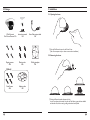
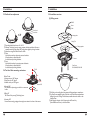
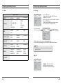
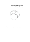
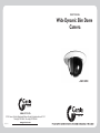
USER MANUAL Wide Dynamic Slim Dome Camera · DSF120PX GENIE CCTV LTD. CCTV House, City Park,Watchmead,Welwyn Garden City,Hertfordshire,AL7 1LT Tel +44(0)1707 330541 Fax +44(0)1707 330543 www.geniecctv.com 111010-1 Table of Contents Dear Customer By selecting this product, you have chosen to use a professional camera that guarantees high quality and reliability. We would like to thank you very much for your confidence and request that you read the following instructions carefully before installation and operation.You can then take full advantage of all the advanced features of this product. CAUTION RISK OF ELECTRIC SHOCK DO NOT OPEN CAUTION TO REDUCE THE RISK OF ELECTRIC SHOCK, DO NOT REMOVE THE COVER (OR BACK). NO USER SERVICEABLE PARTS INSIDE. REFER SERVICING TO QUALIFIED PERSONNEL. The lighting flash with an arrowhead symbol, within an equilateral triangle is intended to alert the user to the presence of uninsulated dangerous voltage within the product’s enclosure that may be of sufficient magnitude to constitute a risk of electric shock to persons. The exclamation point within an equilateral triangle is intended to alert the user to the presence of important operating and maintenance (servicing) instructions in the literature accompanying the appliance. 1. Precautions ----------------------------------------------------------------- 4 2. Limitation of liability ------------------------------------------------------- 5 3. Disclaimer of warranty --------------------------------------------------- 5 4. Package ---------------------------------------------------------------------- 6 5. Installation ------------------------------------------------------------- 7~10 6. Name and function of each part---------------------------------------- 11 7. State-of-the-art image enhance technologies--------------------11~12 8. Other features ------------------------------------------------------------12 INFORMATION This equipment has been tested and found to comply with limits for a Class A digital device, pursuant to part 15 of the FCC Rules. These limits are designed to provide reasonable protection against harmful interference when the equipment is operated in a commercial environment. This equipment generates, uses, and can radiate radio frequency energy and, if not installed and used in accordance with the instruction manual, may cause harmful interference to radio communications. Operation of this equipment in a residential area is likely to cause harmful interference in which case the user will be required to correct the interference at his own expense. WARNING Changes or modifications not expressly approved by the manufacturer could void the user’s authority to operate the equipment. 9. OSD Key ------------------------------------------------------------------ 13 10. How to operate key functions-----------------------------------14~21 11. Trouble shooting guide ------------------------------------------------22 12. Dimension --------------------------------------------------------------- 22 CAUTION – To prevent electric shock and the risk of fire hazards Do NOT use a power source other than that specified. This installation should be made by a qualified service person and should conform to all local codes. 13. Specification ------------------------------------------------------------- 23 1. Precautions · Please read the manual carefully before the installation in order to make use the camera to be set up correctly and to have the best picture quality. · Please keep the manual in good condition for your future reference and service application. · Installation and services should only be carried out by an authorized personnel according to local safety regulations. · If any liquid or solid matter gets into the housing, immediately disconnect the camera from power supply and have it checked by your authorized dealer before reusing. · Avoid installing the camera at extremely hot or cold places. · If you are not a certified person, never try to dismantle the camera. To avoid electric shock, never remove the screws or covers. There are no parts inside that need maintenance by the user. All maintenance should be carried by qualified personnel. · Avoid installing the camera at a place of high humidity. · Avoid installing the camera at the place exposed to gas or oil. · Keep the top glass of the lens always clean in order to obtain the best picture quality all the time. Be careful not to be stained by fingerprint. · Please give a special attention to keep the unit from dangerous drop or external shock during the process of transportation or handling. · Never try to touch the camera in wet hand. It may cause an electric shock. · Do not expose the camera to radioactivity. It causes a serious damage on the sensor. 4 2. Limitation of liability This publication is provided “AS IS” without warranty of any kind, either express or implied, including but not limited to, the implied warranties of merchantability, fitness for any particular purpose, or noninfringement of the third party's right. This publication could include technical inaccuracies or typographical errors. Changes are added to the information herein, at any time, for the improvements of this publication and/or the corresponding product(s). 3. Disclaimer of warranty In no event shall seller be liable to any party or any person, except for replacement or reasonable maintenance of the product, for the cases, including but not limited to below : (1) Any damage and loss, including without limitation, direct or indirect, special, consequential or exemplary, arising out of or relating to the product; (2) Personal injury or any damage caused by inappropriate use or negligent operation of the user; (3) unauthorized disassemble, repair or modification of the product by the user; (4) Inconvenience or any loss arising when images are not displayed, due to any reason or cause including any failure or problem of the product; (5) Any problem, consequential inconvenience, or loss or damage, arising out of the system combined by the devices of third party. (6) Any claim or action for damages, brought by any person or organization being photogenic subject, due to violation of privacy with the result of that surveillancecamera's picture, including saved data, for some reason, becomes public or is used for the purpose other than surveillance. 5 4. Package 5. Installation 5-1. Opening the dome USER MANUAL Wide Dynamic Slim Dome Camera · DSF120PX Wide Dynamic Slim Dome Camera 1EA Instruction manual 1EA Extra Video output cable 1EA ྙ Push the Push Button forward on the Dome Cover. (Take off a transparent vinyl on dome curvature when installation) 5-2. Removing the dome Tapping screws 4EA Plastic anchor 4EA Drilling template 1EA [Option] Fixed Screws 4EA Adaptor plate 1EA ྙ Pushing the Button forward, unfastens the lock. In order to unfasten the forward lock with the Push Button, grasp the dome bubble and take this off, and the cover, by pulling out backward and upward. 5. Installation 5. Installation 5-3.Varifocal Lens adjustment 5-5. Installation overview (1) Ceiling mount 56 Power Video Zoom Knob Focus Knob Adaptor plate Ceiling Tile ྙ Open dome bubble and cover as 5-1 & 5-2. ྚ Unfasten Tilt Locking Lever by turning counter clockwise and adjust Camera to wanted location. And then, fasten Tilt Locking Lever tightly by turning clockwise. ྛ Adjust focus using Tele-Wide & Near-Far Knob. ྜ Zoom 8QORFNWKH]RRPOHYHUE\WXUQLQJFRXQWHUFORFNZLVH 0RYHWKHOHYHUWRDGMXVWWKH]RRP /RFNWKHOHYHUE\WXUQLQJFORFNZLVH ྜྷ Focus 8QORFNWKHIRFXVOHYHUE\WXUQLQJFRXQWHUFORFNZLVH 0RYHWKHOHYHUWRDGMXVWWKHIRFXV /RFNWKHOHYHUE\WXUQLQJFORFNZLVH 5-4.Tool-free 3-Axis mounting mechanism 7LOWÜ Perfect Tri-axis ̲ Panning axis up to 360° degree ̲ Tilting axis up to 90° degree ̲ Rotation axis up to 180° degree a. Panning 360° Pan Camera Set by turning post which is a camera set holder. Camera Fixed Screw 3+060[3[/($ Dome-Ass'y 5RWDWLRQÜ 3DQÜ b. Tilting 90° Tilt Camera Set by turning Tilt Locking Lever. c. Rotation 180° Rotate Camera set by grasping and turning the serration in the front of the camera. 8 Drilling template ྙ Drill holes on the ceiling after doing paste a drilling template to wanted spot. ྚ Put Fixed Screws supplied in the screw hole on the Dome Base and penetrate drilling holes on the Ceiling Tile. And then, assemble them to the holes on the Adaptor Plate. ྛ After fixing the location of the Camera, push the Dome Ass’y (Dome Bubble and Cover) to the Dome Base. 9 5. Installation 6. Name and function of each part (2) Wall or Slope mount Drilling template RS485 Power Video Dome-Ass'y Tapping Screw Ø4*20L-3EA Camera Set Plastic Anchor Ø6*30L-3EA ྙ Drill holes on the wall after pasting a drilling template to the desired position. 7. State-of-the-art image enhance technologies ྚ Fix Plastic Anchors in the holes. ྛ Fix the Dome Base to the wall using self-tapping Screws supplied. 7-1. Powerful Wide Dynamic range ྜ After fixing the location of the Camera push the Dome Ass’y (Dome Bubble and Cover) to the Dome Base. NORMAL CCD TYPE NORMAL CCD TYPE 10 Pixim WDR Pixim WDR Conventional CCD cameras are unable to process images with simultaneously bright and dark areas, even with BLC. However, this unit utilises a Pixim WDR digital imaging device and can do this, as in the above picture. It’s suitable for bright, bright reflecting areas & locations with lots of windows, such as Banks, Airports etc. When conventional CCD cameras face directly toward strong light there are smear and blooming effects on the picture. However, this unit with its Pixim WDR digital imaging device provides clear subject recognition without such artifacts. 11 7. State-of-the-art image enhance technologies 8. Other features 7-2. Maximum sensitivity with the best sensor and the latest techology 8-1. Camera ID setting Conventional Using the latest Pixim WDR sensor, this unit provides the highest light sensitivity of 0.03 Lux/F1.4 (DSS On). In addition, the built-in Day/Night function completely removes the colour signal noises for an ultra clear night time image quality. Pixim WDR Users can use the camera identification (Camera ID) to assign a name of the camera. The camera ID consists of up to 11 characters. 8-2. Privacy zone masking When the unit is observing a wide area, the captured image can be masked for privacy purposes. Users can easily configure the size and position of the required privacy zones. :LGHUDQJHRI$XWRPDWLF:KLWH%DODQFHÜ.aÜ. False White Balance Pixim WDR Automatic White Balance of this unit provides an extensive range of colour temperature FRQWUROWKDWFRYHUVIURPÜ.WR Ü.JHQHUDWLQJDQDWXUDOcolour image without being red or blue in varying light conditions. 7-4. Sens-up ~ 2x The DSS function means the camera can display bright images even in extreme darkness. ~ 16 x 'XDOVZLWFKLQJSRZHUZ$XWR/LQHORFN The unit builds in highly efficient switching power control that self configures 12VDC or 24VAC input and 24VAC line pulse automatically (Automatic line-lock). Double insulated power design guarantees no ground loop when used with multiple cameras and system equipment together through one power source. 9. OSD Key 9-1. Setting up the Menu UP MENU (PUSH) 32 x Important Tips : Sensitivity can be much more improved when <DSS> is set 2x ~ 32 x. LEFT Caution : When DSS is adjusted to more than 8 times(8x), the picture becomes brighter but the frame rate becomes slower resulting in the picture being displayed in slow motion. RIGHT DOWN 9-2. Cable Connection POWER INPUT(AC/DC) VIDEO OUTPUT (BNC) TRX+(RED CABLE) TRX- (BLACK CABLE) 12 13 10. How to operate key functions 10. How to operate key functions 10-1. Menu 10-2. Settings SETUP menu PRESETS EXPOSURE WDR WHITE BALANCE ืNORMAL SETUP ืOUTDOOR ืINDOOR MIDDLE WHITE BALANCE ATW DAY/NIGHT AUTO.. ืEXPOSURE MODE ืAGC SPECIAL.. ืDNR ืHIGHLIGHT ืCOLOR ROLL ืSENS-UP ืHIGH IMAGE ADJ.. EXIT MENU. ืUSER Select the function using the UP or DOWN button. ืLOW ืATW ืINDOOR ืOUTDOOR 1. Press the SET button ㆍSettings can now be made. The SETUP menu is displayed on the monitor. 2. Select a menu item from the list available by using the UP and DOWN buttons. ืFuntions are selected using up and down buttons. ืThe selected position is displayed in blue. SETUP PRESETS NORMAL EXPOSURE.. WDR MIDDLE WHITE BALANCE ATW DAY/NIGHT AUTO.. Change the status using the LEFT or RIGHT button. IMAGE ADJ.. SPECIAL.. ืMANUAL DAY/NIGHT ืAUTO ืCOLOR ืBW IMAGE ADJ ืFREEZE ืCOLOR GAIN ืFLIP ืGAMMA ืSHARPNESS ืCAMERA ID ืMOTION ืRS485 SETUP ืVIDEO OUT ืPRIVACY SETUP ืRESET ืDZOOM ืSYNC ืRETURN EXIT MENU WDR ืFOCUS ืAWB SPECIAL EXPOSURE.. ืLENS ืMIDDLE NORMAL PRESETS EXIT MENU. 3. Set up a selected item by using the Left and Right buttons. 4. To finish and save the settings, select 'EXIT MENU' and press the SET button. Note An item with the .. icon also has sub-menus. To select a sub-menu, press the SET button. ̰ PRESETS SETUP PRESETS NORMAL EXPOSURE.. WDR MIDDLE WHITE BALANCE ATW DAY/NIGHT AUTO.. IMAGE ADJ.. SPECIAL.. 1250$/1RUPDOHQYLURQPHQW ,1'225,QGRRUHQYLURQPHQW 287'2252XWGRRUHQYLURQPHQW EXIT MENU. 15 10. How to operate key functions 10. How to operate key functions ̰ EXPOSURE ̰G WDR SETUP SETUP PRESETS NORMAL EXPOSURE.. WDR MIDDLE WHITE BALANCE ATW DAY/NIGHT AUTO.. When the SETUP menu screen is displayed, select‘EXPOSURE’by using the Up and Down buttons so that the arrow indicates‘EXPOSURE’. EXPOSURE DC / Manual : Select Lens Type - LENS : To adjust the DC and VIDEO lens focus. - EXPOSURE MODE : To select the number of fields and 50i /25p selectable number of exposure cycles. - AGC (AUTO GAIN CONTROL) : In dark environments, the higher the gain level, the brighter the screen but the higher the noise. OFF / LOW / MIDDLE / HIGH selectable - DNR (Digital Noise Reduction) : The level of background noise in low light decreases automatically as the level of gain changes. LENS FOCUS.. EXPOSURE MODE AGC DNR HIGHLIGHT COLOR ROLL SENS-UP PREVIOUS PAGE. AI THRESH EXPOSURE.. WDR MIDDLE WHITE BALANCE ATW DAY/NIGHT AUTO.. -30 30 36 0 36 PREVIOUS PAGE. EXIT MENU. 50i MIDDLE MIDDLE ON OFF 2X - WDR : When the image has simultaneous bright and dark areas, the Wide Dynamic Range makes both areas distinct. 0 120 255 -48 -14 60 Use the White Balance function to adjust the screen colours. 1. Position the cursor to point to WHITE BAL on the SETUP menu screen, select using the Up and Down buttons. 2. Select the desired mode using the Left and Right buttons. Select one of the following 5 modes, as appropriate. SETUP FOCUS DETECTOR FOCUS METER SET FOCUS REGION.. LOW / MIDDLE / HIGH / USER selectable ̰G WHITE BALANCE 88 PREVIOUS PAGE. PRESETS EXPOSURE.. WDR WHITE BALANCE DAY/NIGHT IMAGE ADJ.. SPECIAL.. NORMAL MIDDLE ATW AUTO.. SET FOCUS REGION OFF / LOW / MIDDLE / HIGH selectable MANUAL WHITE BALANCE RED BLUE -18 -20 20 13 -20 20 PREVIOUS PAGE. - HIGHLIGHT : To optimise the scene when high dynamic range lighting is detected. ON : bright parts of the image are most visible. OFF : dark parts of the image are most visible. - COLOR ROLL : To control a detector that finds colour fluorescent roll. OFF / LOW / MIDDLE / HIGH selectable - SENS-UP : When it is night or dark, the camera automatically detects the light 2X, 4X, 8X, 16X, 32X OFF : Deactivates the SENS-UP function. 2 LIMIT SPECIAL.. DC.. PREVIOUS PAGE. level and maintains a clear picture if this mode is activated. BIAS IMAGE ADJ.. LENS MENU DC GAIN WDR LEVEL NORMAL PRESETS ATW : The ATW mode continuously monitors. INDOOR : Select when the colour temperature is between Ü.DQGÜ. OUTDOOR : Select when the colour temperature is EHWZHHQÜ.DQGÜ. AWB : To obtain the optimum state under the current luminance levels, direct the camera to point toward a sheet of white paper and press the SET button. If the environment changes, including the light source, the white balance will requirere-adjustment. MANUAL : Select to "fine-tune" the White Balance manually. Set White Balance first using the ATW or AWB mode. Afterwards switch to MANUAL mode, fine-tune the White Balance and then press the SET button. Note 8QGHUWKHIROORZLQJFRQGLWLRQV:KLWH%DODQFHPD\QRWZRUNSURSHUO\ In such cases, select the AWC mode. ① When the colour temperature of the subject environment has a very high temperature range (e.g. clear sky, or sunset) ② When the ambient illumination of the subject is low. ③ If the camera is directed toward a fluorescent light, or is installed in a place where illumination changes dramatically, the White Balance operation may become unstable. 10. How to operate key functions 10. How to operate key functions ̰ DAY/NIGHT ̰G SPECIAL SETUP NORMAL PRESETS EXPOSURE.. WDR MIDDLE WHITE BALANCE ATW DAY/NIGHT AUTO.. IMAGE ADJ.. AUTO : This camera has an IR Cut-Filter and automatically changes to the appropriate mode according to lighting levels.To set up the switching time for the AUTO mode press the SET button. COLOR : The picture is displayed in colour. B/W : The picture is always displayed in black and white. SPECIAL.. EXIT MENU. When the SETUP menu screen is displayed, select 'SPECIAL' by using the Up and Down buttons so that the arrow indicates 'SPECIAL'. SETUP NORMAL PRESETS EXPOSURE.. WDR MIDDLE WHITE BALANCE ATW DAY/NIGHT AUTO.. - CAMERA ID : User can enter a unique name for the respective camera. The maximum length of the ID is ten characters. IMAGE ADJ.. SPECIAL.. When the SETUP menu screen is displayed, select 'IMAGE ADJ' using the Up and Down buttons. SETUP PRESETS IMAGE NORMAL EXPOSURE.. WDR MIDDLE WHITE BALANCE ATW DAY/NIGHT AUTO.. FREEZE OFF FLIP OFF SHARPNESS COLOR GAIN -8 4 8 2 8 GAMMA SPECIAL.. PREVIOUS PAGE.. 45 - FREEZE :View still pictures. -8 IMAGE ADJ.. 25 100 OFF / ON selectable SPECIAL - FLIP : OFF / HORIZ / VERT / BOTH selectable HORIZ - SHARPNESS : The outline of the video image becomes cleaner and more distinctive as the level of SHARPNESS increases. If the level gose up excessively, however, it may affect the video image and generate noise. The available range of level is -8 ~ 8 VERT BOTH - COLOR GAIN : To control the colour level in the video. The available range of level is -8 ~ 8 - GAMMA : Users can change the gamma setting between 25 and 100 OFF CAMERA ID VIDEO OUT.. DZOOM MOTION PRIVACY SETUP.. SYNC RS485 SETUP.. RESET RETURN 3OHDVHVHOHFWWKHVHWXSEXWWRQZKLOHLQ2QPRGH OFF OFF 6HOHFWWKHGHVLUHGSRVLWLRQZLWKWKHVHOHFWRU INT CAMERA ID EXIT MENU. OFF <RXFDQFKRRVHWKH21DQG2))ZLWKWKHVHOHFWRU If you select ON, the entered camera ID is displayed at the selected position in the video picture (normal operation). EXIT MENU. ̰ IMAGE ADJ ID CAM-001 POSITION PREVIOUS PAGE. UP-LEFT 0RYHWKHFXUVRUWRWKHOHWWHUUHTXLUHGE\XVLQJWKH Set-Up button. 6HOHFWDQ,'IURP$%a<=DEa\]aE\XVLQJWKH LEFT and RIGHT buttons. 5HSHDWWKHDERYHVWHSVXQWLOWKH,'LVFRPSOHWH CAMERA ID ID CAM-001 POSITION UP-LEFT PREVIOUS PAGE. VIDEO STANDARD VIDEO SELECT VIDEO LEVEL 80 SYNC LVL 0 -16 BURST LVL 0 -16 COLOR BAR PREVIOUS PAGE.. PAL 110 150 15 15 OFF 6HOHFWWKHSRVLWLRQZKHUHWKH,'LVWREHGLVSOD\HG by using the LEFT and RIGHT buttons. - VIDEO OUT : Move the cursor to select the video system VIDEO STANDARD :You can control NTSC / PAL,Video level, Sync level, Burst level. 10. How to operate key functions DZOOM ZOOM 1 1 PAN 0 -100 100 TILT 0 -100 100 12 PREVIOUS PAGE.. MOTION DETECTION ACTIVITY THR. MESSAGE TIME 0 25 225 1 3 10 SETUP MOTION ZONE.. PREVIOUS PAGE. MOTION ZONE SETUP - DZOOM : Digital P/T/Z are used to create a zoom lens effect. Zoom Factor (1X to 4X), Pan (±100%, center of image can be moved to left and right edges of screen), Tilt (±100%, center of image can be moved to top and bottom edges of screen) - MOTION : This product has a feature that allows you to observe movements of objects in on the screen, hence a single individual can conduct supervision efficiently. The camera detects an object's movement by sensing disparity of outline, and level of brightness and colour. White : MOTION ZONE Position movement Green : MOTION ZONE Size enlargement Red : MOTION ZONE Size reduction For MOTION ZONE Confirm, long press SET button 10. How to operate key functions LINE LOCK V PHASE 0 519 624 PREVIOUS PAGE. - SYNC : Two synchronisation modes are available, INTERNAL and EXTERNAL LINELOCK. In LINE-LOCK mode, it synchronises the video signal between cameras without a synchronous generator. The line-lock synchronisation is only used in areas of 60Hz (NTSC) / 50Hz (PAL). INT : Internal synchronisation LL : External line-lock synchronisation - If 'LL' is selected, it can be adjusted to the desired phase. Press the SET button. - Adjust to the desired phase from 0 to 624. RS485 SETUP CAMERA # : 1 < 1 > 255 PROTOCOL PELCO-D BAUD RATE < 2400 > < 4800 > < 9600 > < 19200 > PREVIOUS PAGE. - RS485 SETUP : This function sets up the camera communication status when controlling the camera through an external control device. - RESET : Resets the camera settings to the factory defaults. PRIVACY MASK SETUP PRIVACY MASK OFF MASK COLOR WHITE - PRIVACY SETUP : Hide an area you want to hide on the screen. PREVIOUS PAGE. ENABLE MASKS (1 to 6) ENABLE MASKS (7 to 12) MASK 1 ON MASK 7 OFF MASK 2 OFF MASK 8 OFF MASK 3 OFF MASK 9 OFF MASK 4 OFF MASK 10 OFF MASK 5 OFF MASK 11 OFF MASK 6 OFF MASK 12 OFF PREV. NEXT. PREV. White : PRIVACY-ZONE Position movement Blue : PRIVACY-ZONE Size enlargement or reduction For PRIVACY-ZONE Confirm, long press SET button ̰G EXIT MENU Saves all the setting menus and then exits. 11.Trouble shooting guide 13. Specification Before sending the camera back for repair, check the items below. If the problem persists after checking these items, contact your distributor. Problems Troubleshooting Nothing appears on the screen. · Check the power connections. · Check the video signal line connection. The video image is not clear. · Make sure the lens and dome cover are clean. - Dirt or fingerprints affect the image and can cause blooming or reflection. Gently wipe any dirt or fingerprints from the lens and dome using a soft cloth. · Check and adjust the monitor contrast. The screen is dark. · Check and adjust the monitor contrast. · If there is any intermediate equipment, check and set the Hi-z terminations correctly. · Check that the power supply is within specification. - If the power cable is too long, it may require a higher rated power supply or additional power or video amplification. The camera’s surface is too hot and black stripes appear on the screen. · Check if the power supply is regulated and is within the standard requirement of the product. Colours are not quite right. · Check the <white balance> setting. Weak power level. · Check if the distance of the cable installation is too long, and the cable is UL standard. Using a low grade cable or a long distance cable installation can cause a serious voltage drop. Check the voltage output level at the cable and change the power source if necessary. Take special care not to supply too much power to the camera as this is equally damaging. 12. Dimension (mm) MODEL Image Sensor EffectivePixels Pixels Effective DSF120PX 1/3" Pixim WDR digital imaging device 410,000 pixels 758(H) x 540(V) H.Resolution 690 HTVL effective Sync System Scanning System Video Output S/N Ratio Internal NTSC/PAL - compatible 1.0 Vp-p composite. 75 Ohms More than 50 dB (AGC Off) Min. Illumination 0.1Lux at F1.4 (DSS off), 0.01Lux at F1.4(DSS on) Noise Reduction 3D DNR Motion Adaptive,2D DNR(ON/OFF) Camera ID CAM1~CAM255 selectable by OSD Gamma Correction White balance Smear Effect Power Source White balance Operating Current (Max) Lens Operating Temperature Standard r=0.45 2,000Ü.aÜ. ATW / Indoor / Outdoor / AWB / MANUAL selectable by OSD 0.005% 12VDC, 12VDC/24VAC Dual Power 12VDC : 200mA, 12VDC/24VAC Dual Power : 300mA at 12VDC/150mA at 24VAC 3.3~12mm Varlfocal Lens (F1.4) Ü)aÜ)Ü&aÜ& Humidity Within 90% RH Measurement (mm) 180(Ȱ)x81(H) Weight (Approx.in grams) 500g OSD MENU WDR White balance Gain Control Low/Middle/High/User(0~36) ATW/AWC/MANUAL - User selectable 26dB/28dB/34dB/38dB/40dB/42dB/45dB/47dB/50dB/ selectable by OSD Sens-up Off/2x~32x(DSS) Day/Night Auto/Colour/BW Specifications are subject to change without prior notice.