1
The
Colne Robotics
A R M D R O I D
Construction and Operation Manual
Published by
COLNE ROBOTICS LIMITED
1 Station Road
Twickenham
Middlesex TW1 4LL
[C] Copyright 1981
CONTENTS
Page N o .
1.
Introduction
*1-1*
2.
Mechanics
2.1
2.2
2.3
2.4
2.5
3.
*2-l*
*2-2*
*2-3*
*2-4* - *2-8*
*2-9* - *2-14*
Electronics
3.1
3.2
3.3
4.
Description
Technical Hints
Tools
Mechanical Parts
Assembly
Description
Component List
Assembly
*3-1* - *3-3*
*3-3 * - *3-3 *
*3-4* - *3-5*
Software
4.1
4.2
4.3
4.4
4.5
4.6
4.7
Introduction
*4-l*
Loading
*4-l*
General Description
*4-l*
Command Explanation
*4-l* - *4-4*
Introductory Demonstration Sequence
*4-5*
Detailed Software Description
*4-6* - *4-48*
Applications
*4-48* - *4-58*
INTRODUCTION
The development of Armdroid I arose as a result of a survey of
industrial robots. It became apparent that educationalists and
hobbyists were starting to show interest in medium and small
sized robotic devices. There was however no robot on sale anywhere in the world at a price suitable to these markets. The
Armdroid micro-robot now fulfils this role, providing a
fascinating new microcomputer peripheral.
Purchase of the robot in kit form enables the assembler to
understand its principles and allows for modification, although
of course the machine may also be purchased ready assembled.
This manual has been compiled as a guide to the construction and
operation of your Armdroid micro-robotic arm, and should be
followed carefully. There are separate sections covering both
the mechanical and electronic aspects of the robot, as well as
the specially written software.
*1-1*
MECHANICS
2.1
Description
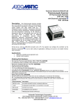
The ARMDROID consists of five main parts.
The base
The base performs not just its obvious function of supporting
the rest of the arm. It also houses the printed circuit boards
and the motor that provides the rotation.
The Shoulder
The shoulder, which rotates on the base by way of the main
bearing, carries five motors and their reduction gears which
mesh with the reduction gears on the upper arm.
The Upper Arm
The lower end of the upper arm carries the gears and pulleys
that drive the elbow, wrist and hand. It rotates about a
horizontal axis on the shoulder.
The Forearm
The forearm rotates about a horizontal axis on the upper arm
and carries the wrist bevel gears.
The Wrist and Hand
The two wrist movements, the rotation about the axis of the hand
("twist") and the rotation of the hand about a horizontal axis
("up and down"), depend on a combination of two independent
movements. The twist is accomplished by rotating both bevel
gears in opposite directions, while the up and down movement
is done by turning the gears in the same direction. Combinations
of the two movements can be got by turning one bevel gear more than
the other.
The three fingered hand with its rubber fingertips has a
straightforward open and shut movement.
*2 - 1*
2.2
Technical Hints
1.
FITTING BELTS ONTO PULLEYS
Fit belt over small pulley first and then work onto unflanged
edge of large pulley a little at a time - do not attempt to get
belt fully onto pulley until you have got it on by one or two
millimetres all round.
(Belts can be damaged if they are
crimped). When fitted belts should not be drum tight there should
be just a little play, or friction will rear its ugly head again.
2.
FITTING SWITCHES
On initial fitting do up bolts only enough to hold switches in
position. Finally after gears are fitted swing switches so that
they clear gears by approximately one millimetre and finally tighten.
3.
FITTING PULLEYS TO MOTORS
You will find the motor shafts have end float with a light spring
action pulling the shaft in. Do not pull shaft out against this
spring when fitting pulley as this will cause friction and loss of
effective motorpower.
4.
LUBRICATION
Use light oil (three in one or similar), just a drop on all parts
that slide or pivot. DELRIN is a self lubricating material but the
friction is a lot lower with a drop of oil. We only have
limited power from the motors so we want to make the most of it,
so work spent on eliminating friction
will pay performance
dividends. Check all bores and bearings for free running - any
tightness is usually caused by burrs or stray bodies in bores.
Remove burrs from Delrin with a sharp knife, from metal with a
scraper.
Disposable hypodermic is ideal for lubricating - scrounge one from
your local friendly GP or Hospital.
*2 - 2*
REED SWITCH POLICY
Micro-switches are included in the assembled and unassembled
Armdroid packages as optional extras. It must be stressed,
however, that the machine will function perfectly well without the
micro-switches, but a check must be kept on the number of complete
revolutions of the base. Any more than 1.5 turns will put a
strain on the stepping motor leads where they connect to the
printed circuit boards.
To prevent any difficulty in the fitting of reed-switches
after the initial assembly the magnets will be inserted
during manufacture. This will save the dismantling of the
Armdroid in the field. Magnets will be included in all the
kits.
There will be a nominal charge of £15 for the inclusion of reedswitches in both the assembled and unassembled Armdroids.
PART NUMBERS INVOLVED: *O9*1O*15*16*18/16*18/12*
*2-2a*
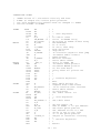
2.3
TOOLS LIST INC.
Lubricants etc
General and small circlip pliers
7mm spanner
5.5mm spanner
supplied
supplied
Metric steel rule, (part identification)
Hypodermic syringe or small oilcan and 3 in 1 oil
"Superglue" and if possible "Loctite"
Cold vaseline or cycle bearing grease
Tweezers
Allen keys for M3 grub screws M4 grub screws M4 bolts
-
supplied
supplied
supplied
Lightweight hammer (fitting rollpins)
*2 - 3*
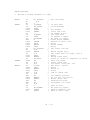
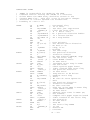
2.4
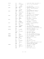
ASSEMBLY
Description of item
Part No
Base
01
Base Bearing support column
02
Base motor
03b
Base motor short pulley 20 tooth
04b
Base reduction gear spindle
05
Turned thick wide washer
06
16mm x 2mm
Reduction gear
07
Base belt (medium length) 94 teeth
08m
Base switch support 12mm x 11mm
09
Base switch
10
Shoulder pan
11
Shoulder bearing ring
12
Base gear (large internal dim)
13
Bearing adjusting ring
14
Hand motor support bracket
15
Hand motor
03h
Hand switch bracket
16
Motors -
Upper arm
03u
Fore arm
03f
Wrist action
03w
Motor pulleys
-
Upper arm
04u
Fore arm short 14 tooth
04f
Wrist action long 20 tooth 04w
Hand
short 20 tooth
*2 - 4*
04h
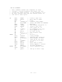
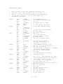
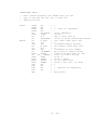
DESCRIPTION OF ITEM
Part No
Shoulder Side Plates
Switch support bar 107mm x M3 at ends
Support bar spacers M3 clearance X
Motor support bracket stiffener
107mm x M3 at ends
Support Bar spacers
Reduction gears
Reduction gear spindle 96mm x 6mm
Drive belts
Upper
small
Upper
Upper
Gears
long = 114 teeth
medium = 94 teeth
short = 87 teeth
Arm Drive Gear
internal dim no drum
arm side plates
arm brace
wrist action
hand
action
fore arm
Idler pulley
Shoulder pivot 96mm x 8mm spindle
Fore arm side plates
Fore arm brace
Fore arm pulley
*2 - 5*
017
019
018/16
018/12
019
018/54
018/41
020
021
08/l
08/m
08/s
021
022
023
024
025
026
027
029
030
031
032
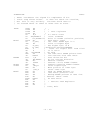
Hand
Fore/Upper arm
Wrist action
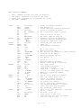
DESCRIPTION OF ITEM
Elbow Idler pulleys
Part No.
hand
wrist
033
Elbow spindle 65mm x 6mm
034
Wrist bevel gear carrier
035
Wrist guide pulleys
036
Wrist bevel gears (flanged)
037
Wrist pivots
.
038
Hand bevel gear (no flange)
039
Finger support flange
040
Hand pivot
041
Finger tip plates
041
Finger cable clamp
042
Small finger spring
043
Finger tip pivot
044
Middle finger plates
045
Middle finger pivot
046
Large finger spring
047
Finger base
048
Long finger pins 16mm x 3mm
050/l
Short finger pins 13mm x 3mm
050/s
Small finger pulleys
051
Large finger pulleys
052
Large hand sheave pulley
053
Small hand sheave pulley
054
Hand sheave pin
055
Finger tip pads
056
Base pan
057
*2 - 6*
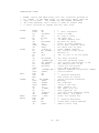
DESCRIPTION OF ITEM
Part No.
Board Spacers
018/41/54
Spacer bars for boards
058
Rubber feet
059
Cable springs wrist action short
060
Cable springs grip,
061
elbow long
PREPARATION AND FIXINGS ETC
DESCRIPTION OF ITEM
Item No.
Magnets
101
Bearing adjustment ring grub screws
M4 x 8mm
NB + self made plug to protect the
102
fine bearing thread
Turned cable clamps 6 x 6mm M3 tapped
103
Cable clamp grub screws M3 x 4 pointed head 104/105
Crimped type cable clamps
crimped eyelets
106
Gear Cable grub screws M4 x 6mm flat head
107
Bushes
8mm bore long with flange
shoulder
Shoulder pivot spindle spacer
108
108a
6mm bore short with flange
- elbow
8mm bore long with flange
wrist
8mm bore no flange
main gear inserts
Gear to sheet metal screws M3 x 6
slot hd CSK
Spring pillar and base switch
M3 x 10 cheese head
113
Base bearing to shoulder pan
M4 x 16 CSK socket head
114
*2 - 7*
109
110
111
112
DESCRIPTION ITEM
Item No.
Motor bolts, Base bearing to base
M4 x 10 Elbow spindle hex hd
115
Hand to finger, hand to bevel gear
M3 x 6 cheese hd
116
Shoulder spindle
M5 x 10 hex hd
117
General sheet metal fixing
M3 x 6 hex hd
118
M4 Nuts
119
M4 Washers
120
M4 Shakeproofs elbow spindle
121
M5 shakeproofs shoulder spindle
122
M3 Nuts
123
M3 washers - switches
124
6mm steel balls - base bearing
125
Magnetic reed switches
010 (101?)
Driver board
126
Interface board
127
Edge connector
128
6mm Washers
129
Roll pins
130
4.5mm circlips
131
3mm circlips
132
Elbow spacer
133
*2 - 8*
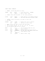
2.5
ASSEMBLY
Preparation
Study the parts list, drawings and the parts themselves until
you are sure you have identified them all. Assemble the tools
suggested in the list of tools (2.3). Read carefully
technical hints section. Solder 12 inches of ribbon cable to each
motor. Glue magnets (101) into the slots in the reduction gears,
noting that the hand gear (25) needs no magnet. Check that the
adjusting ring (14) of the main bearing screws easily onto its
base. Clean both if necessary. Insert bushes into the arms,
if necessary using a vice, but taking care not to distort the
sheet metal.
Construction
Fit base bearing support (2) column inside base (1). (M4 bolts,
nuts.) NB NUTS INSIDE BASE
Bolt 1 motor (shorter cable) inside base. (M4 hex bolts, washers
on motor side - nuts on inside). Fit pulley to spindle base of
motor with the grub screw at the top (04b). Fit base reduction
gear spindle (07) to base. (Thick turned washer, M4 hex bolt)
Fit reduction gear and belt. Place a small drop of oil on the
reduction gear spindle before fitting reduction gear.
When fitting belts they should be placed fully on the motor spindle
and worked gently onto the reduction gear, a small section of their
width at a time. (see general hints on lubrication)
Fit base switch support. (M3 hex bolt) NB DRAWING FOR POSITION.
Fit base switch and run wires through adjacent hole. (M3 x 10
cheesehead, washer)
Fit bearing ring (12) (long spigot down) through shoulder base pan
(11) from inside. The base gear (13) fits on the lower face of the pan,
with the magnet at 2 o'clock as seen from inside the pan with the
flange at the top. (M4 countersunk x 16mm bolts, nuts)
(This step and the next are simpler with some help from an
assistant). Put shoulder base pan (gear side up) on to 3in supports
(books etc,) so that the bearing support column can be inserted.
Practise this movement to make sure all is well. Smear vaseline
from a fridge, or grease on the bearing track of the flange, and
using tweezers to avoid melting the vaseline carefully place 24 ball
bearings round the flange, embedding them into grease. There will
be a slight gap when all the balls are in place. Invert the base
and insert the threaded bearing support column inside the bearing
ring taking care not to dislodge any of the balls so that the base
pan meshes with the base gear. Keep the two parts level in the
same relationship by taping the parts together with a piece of wood or
a spanner 5mm thick between the motor pulley and the shoulder
base pan.
*2 - 9*
Large rubber bands can be used instead of tape.
to hold the parts for you will be useful here.
An assistant
Turn the assembly the other way up (the base is now on the bench
with the shoulder base pan above it. Put more grease round the
bearing track and embed 24 more ball bearings in it. Gently
lower the adjusting ring (14) on to the threaded base and then
screw the finger tight, remove with tape, adjust the ring until
the base pan moves freely without play then tighten the grub screw,
inserting a small wood plug to protect the bearing thread.
(M4
grub screws)(102). The bearing may need adjusting after some
use as it beds in.
Fit hand motor bracket (15) to shoulder base pan (M3 bolts) then
the hand motor O3h(M4) and the hand motor pulley. Then fit the hand
reed switch-bracket (M3) and the switch (M3 x 10 cheesehead bolts).
Fit motors to the shoulder side plates (17) and feed the cables
through the holes towards the inside. The bolts which are next
to the reduction gears should be placed nut out to prevent the
reduction gears catching on the end of the bolts. Fit correct
pulleys (04u/f/w) to the motor spindles noting which pulleys from
the drawing, tighten the grub screws.
Fit the shoulder plates. This is simplified by loosely tightening
the end bolts to support the weight. Feed the motor cables down
through the main bearing (M3).
Slide switch support (19) bar through spacers (18), switches (101)
and motor support bracket (see drawing for correct order of spacers).
You will need to be able to adjust the position of the reed switches
after the arm is fitted so that they clear the gear wheels
ie tangential to shoulder pivot. Fit the motor support stiffener bar
and spacers. Leave nuts finger tight. (M3 nuts).
Assemble reduction gear support bar (21), assemble with the correct
length drive belts (08s/m/l) over each gear, reduction gears facing
in correct direction and the thin metal M6 washers at either end.
(see drawing) Slide gently into position and bolt in the support
bolts (M4 a 10mm) Fit the belts round the motor pulleys.
Put upper arm drive gear on the outside of the upper arm side plate.
The magnet should be at 1 o'clock, viewed from the gear side of the
arm. (M3 CSK screws x 6mm) Fit a brace to one upper arm side
piece (22), then fit the other side piece to the brace. Fit all
bolts and nuts before tightening any of them. Check 8mm shoulder
spindle (29) slides freely through accute bushes in upper arm side
pieces and through bores of drive gears, pulleys and spacers.
Assemble by sliding shaft from one side and threading gears,
pulleys and spacers on in the correct order of orientation - use
drawing.
*2 - 10*
Fit pulley (32) to the outside of the forearm side plate (30)
(M3x6mm)(countersunk screws). Fit a brace to one forearm side
plate, then fit the other side plate to the brace. Check for
squareness before finally tightening bolts.
Put elbow pivot through bushes and an 8mm bar through wrist bushes.
(M3 bolts, nuts) Check fit before assembly. Assemble the pulleys
(33) on the elbow spindle (34), lubricate and fit it to the large
arm, and bolt through into spindle. (M4 bolts, washers)
Assemble the wrist bevel gear carrier (35) and wrist pulleys (36)
and then tap the roll pins gently home with a small hammer,
supporting aluminium gear carrier to prevent distortion.
Fit the wrist gears on the bushes (37) from the outside. Fit
bevel gear carrier (35) between the wrist bevel gears (37), line
up holes in end of wrist pivot (38) bores with tapped hole in
carrier by peering down pivots. If you do not have a screw gripping
or magnetic driver use a little piece of masking tape or sellotape
to fix M3 cheesehead screw to the end of your screwdriver in such
a way that it will pull off after tightening - check gears pivot
freely on pivots and that the whole assemble can pivot in oilite
bushes (drops of oil on faces of gears and pivots)
Screw the finger support flange (40) to the hand bevel (39).
(M3 x 6mm cheesehead screws) Screw the hand pivot (41) to the bevel
gear carrier (35). Tighten on a drop of loctite if available,
gently by turning a pair of pliers inside it. The bevel gears should
be positioned with their grub screws pointing towards the hand when
the hand and the forearm are in line (see drawing).
Assemble the fingertip (42) and cable clamp (43) with the small
spring (44) on the pivot (45), and clip together with large
circlips on the cable clamp. The spring should be positioned so
that the "back" of the spring is on the knuckle side of the
fingertip, thus tending to open the hand.
Assemble the middle finger (46) and its pivot (47) with the large
spring (48). Fix to the finger base (49) with the long pin (50/L)
(16mm x 3mm) and two small circlips (see drawing). Fix one
circlip to the pin before one begins to assemble.
Join the fingertip to the middle section with the short pin (50/S)
(13mm x 3mm) and two small circlips.
Cut off one end of the tip spring about 8mm-10mm beyond its hole.
Level with its hole bend the spring through a right-angle to secure
it. Repeat at the other end. Trim the inner end of the middle
finger spring flush with the end of the finger end and treat the
outer end as above.
*2 - 11*
Fit the small pulley (51) to the finger middle section using a short
pin (13mm x 3mm) and two small circlips. Fit the larger pulley (52)
to the finger base with a long pin (16mm x 3mm) and two small
circlips.
Screw the finger base to the finger support flange. Make sure that
the fingers are evenly spaced and do not interfere with each other,
and then tighten.
(M3 x 6mm cheesehead)
Assemble the large and small hand sheave pulleys using the large
circlip on hand sheave pin (55).
*2 - 12*
CABLE THREADING
Slide arm into shoulder, you will need to align the reduction
pulleys between the main drive gears as you lower the arm into
place, and assemble using M5 hex head bolts and shakeproof
washers. Tighten and check the reduction gears "mesh" correctly
and the arm moves freely.
Connect grip action cable tail to shoulder base pan via the spring
correctly placed over the pulley and tension using the normal method
with the cable clamp.
Glue strips of rubber to finger tips using superglue.
The driver and interface board should be bolted to the base pan
using the spacer bars (58) and spacers. Bolt base pan (57) to
base (M3 x 6mm hex h e a d ) .
Hints:
a)
Useful tools are:
2 or 3 'bulldog clips' to maintain the tension in the cable
over completed sections of each cable while the remainder
is threaded. Masking tape can also be used for this purpose,
b)
Ends of the cable can be prevented from fraying by placing
a drop of 'superglue' on the end of area where it is to be
cut. The excess should be wiped off on a piece of paper.
NB. This process also stiffens the end which is useful when
threading the cable through the pulleys.
c)
Ensure all grub screws are in position but are not obstructing
the cable holes. Also check there are no burs remaining
from machining blocking the holes.
d)
The cables can be threaded before the arm is bolted for the
shoulder which eases the problems of access considerably.
The 'grip action' cable tail can be taped or clipped to the
arm and connected and tensioned with its spring after the
arm is fitted to the shoulder,
e)
When tensioning the cable, if it is passed through the clamp
and back, then connected to the spring adequate tension can be
applied by pulling the 'free tail' and then nipping it with the
grub screw. A friend will be useful if around, but it is
quite possible without.
The correct tension can be easily
judged, as when completed the coils of the spring should be
just separated, though this is not critical.
*2 - 13*
f)
During threading the correct 'route' can be ascertained
from the expanding drawings. It is very important these
should be followed exactly, especially the position of the
grub screws when they are tightened on the cable. If this is
wrong it will affect the performance of the arm.
g)
Care should be taken to avoid the cable kinking or crossing
itself on the drums.
h)
Experience has shown that the best order to thread the
cables and lengths to use.
(Excess can be trimmed easily
later but makes tensioning simpler)
First
-
Wrist cables one at a time.
1.47m
Second
-
Elbow cable (set up the spring
pillar first - M3 x 10mm cheesehead
and 2 M3 hex full nuts) attach
crimped cable clamp to forearm first
using M3 x 10 cheese head and two
nuts as a cable pillar.
0.95m
Single finger cable (fix to the
hand sheave pulley using M3 x 6mm
cheesehead and crimped cable clamp.
0.18m
Double finger cable (loop over
small hand sheave pulley on grip
action pulley and adjust so that
G A P is even when pulleys are
evenly positioned).
0.36m
Grip action cable (start at end
fixed in cable drum and stick
other end to arm while fitting
it to the shoulder then tension
with the spring to the shoulder
base pan).
1.3 m
Third
Fourth
Fifth
i)
-
-
Ends using the crimped cable eyelets should be
through the eyelet and a small thumb knot tied
the cable slipping before crimping the bracket
crimping or ordinary pliers. So not crimp too
or you may cut through cable, though KEVLAR is
*2 - 14*
(each)
threaded
to prevent
using
tight
very tough,
ELECTRONICS
3.1 Description
The Interface
To enable the Armdroid to function with as wide a range of
microprocessor equipment as possible, the interface is designed
round a standard 8-bit bidirectional port. This may be latched
or non-latched. If non-latched, the interface will normally
be used to input data to the micro.
In the output mode the port is configured as follows. The eight
lines are defined as four data bits (D8-D5), three address bits
(D4-D2) and one bit (Dl) to identify the direction of data
travel on the port. Four data lines are provided so that the
user can control the stepper motor coils direct from computer.
The address bits are used to channel the step pattern to the
selected motor. The three address bits can define eight states,
of which 1-6 are used to select one of the motors, while states
0 and 7 are unallocated.
Dl indicates the direction of data travel, to the motors when
Dl is low, from the microswitches, if installed, when Dl is
high. The transition of Dl from high to low generates a pulse
which causes the step pattern to be latched into the addressed
output latch.
In the input mode D8 - D3 are used to read the six microswitches
on the arm. These reed switches and magnets provide a "zero"
point for each of the movements of the arm, which can be used as
reference points for resetting the arm in any position before a
learning sequence begins.
D2 is spare. It is an input bit which can be buffered and used
for an extra input sensor, allowing the user to connect a
'home brew' transducer to the system.
The interface circuitry consists of twelve TTL components which
decode the data and route it out to the selected motor driven
logic. ICl and IC2 buffer the data out to the decoder and
latches. IC6 decodes the three input address bits to provide
eight select lines, six of which are for the latches IC7 - IC12.
*3 - 1*
INTERFACE ONLY
Dl is buffered and fed into a monostable (IC4) to generate
a clock pulse. This causes the decoder to provide a latch
pulse for approximately 5OOns to the addresses motor control
latch. Dl is tied to pull-up resister (Rl) so that the line
is high except when are output from the microprocessor. The
buffers ICl and IC2 are enabled by the buffered output of bit
1 so that data are fed to the latch inputs only when bit 1 is
low. The bit 1 buffer is always enabled because its enable
is tied low.
The microswitch inputs are buffered by IC5 which is enabled
by the complemented output of bitl, so that when bitl is high
IC5 is enabled, and the contents of the microswitches will be
input to the microprocessor. This allows the user to operate
the arm under bit interupt control, giving instant response to
a microswitch change and avoiding having to poll the microswitches. The six microswitch inputs are pulled up; thus the
switches can be connected via only one lead per switch, with
the arm chassis acting as ground.
THE MOTOR DRIVERS
the motor drivers are designed so that the arm can be driven
from the output of the computer interface circuitry.
The six motor driver stages need two power supplies:
about 3A and 5v at 150 MA.
15v at
The four waveforms QA-QD are then fed into IC's 13-16 which
are 7 x Darlington Transistor IC's. These provide the high
current needed to drive the stepper motor coils, the driving
current being about 300 MA at 15v.
*3 - 2*
INTERFACE DRIVER BOARD
ITEM
VALUE
QUANTITY
Resistors
Rl
R2
R3-8
R9
RIO
Rll
R12
R13
R14
R15-R2O
1K0
1OK
2K2 resitor
network
1K8
1K8
1K8
15K
1OK
18ohm 5w
1KO
1
3
1
2
1
6
Capacitors
Cl
C2
C3-C15
lOOp polystyrene
l.Ovf Tant
lOnf ceramic
Semiconductors
IC1
IC2
IC3
IC4
IC5
IC6
IC7-IC12
IC13-IC16
IC17
ZD1
74LS 125
74LS 125
74LS 04
74LS 123
74LS 366
74LS 138
74LS 175
ULN2oo3A
UA 7805
BZX 13v ZENER
Miscellaneous
MXJ 10 way edge connector
5 way PCB plug and socket connector
Through Pins
16 pin IC sockets
14 pin IC sockets
4 way modified PCB plug and socket
*3 - 3*
1
1
13
GENERAL ASSEMBLY SEQUENCE FOR THE PC BOARD
A
Fit all of the through pins to the board.
B
Fit and screw the 5v regulator to the board.
C
Identify and fit the resistors and the 13v zener to the
board. The black band v points to the motor connectors
(on the zener DIODE).
D
Identify and fit all capacitors to the board.
E
Solder the 2k2 resistor network, IC sockets, and the
4 and 5 way PCB plugs to the board.
Solder the 10 way socket to the board.
G
NOTE:
Refer to the overlay diagram and parts list to ensure that the
resistors, capacitors, IC,s and other parts are inserted into
the correct locations on the PC Board.
BASIC BOARD CHECKS
A
Check the board for dry joints and re-solder any found.
B
Hold the board under a strong light source and check the
underside to ensure there are no solder bridges between
the tracks.
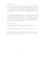
FITTING THE PC BOARD TO THE BASE OF THE ROBOT
The PCB should be fitted to the base plate using the nylon
pillars provided.
MOTOR CONNECTION
Connect the motors to the 5way sockets, ensuring correct 15v
polarity, via the ribbon cable, refering to the diagram provided
to ensure correct connection.
POWER CONNECTION
Connect the power to the modified 4way socket ensuring correct
polarity as shown below.
Polarising pin
15v = Brown = Pin 2 on I/P connector
Blue - Pin 1 on I/P connector=Ov
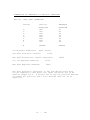
NOTE
A number of diagrams are given, explaining in detail the internconnections between the motors and the PCB, if the motors are
connected in the manner shown then the software provided will
map the keys 1-6 and q,w,e,r,t,y to the motors in the following way
1, q, = GRIPPER.
4, r, = forearm.
2, w, = left wrist.
5, t, = shoulder.
3, e, = right wrist.
6, y, = base.
as shown in the diagram, the two middle pins of the stepper motors
should be connected together and to 15v.
*3 - 4*
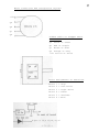
c
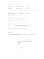
Motor Connection And Designation Layouts
+15v
QD
QB
QC
QA
Ribbon Cable To Stepper Motor
Connections
Qa Black or Green
Qb Red or Purple
Qc Brown or Blue
Qd Orange or Grey
+15v Yellow or white
Motor Assignments To Functions
Motor
Motor
Motor
Motor
Motor
Motor
1
2
3
4
5
6
=
=
=
=
=
=
X pin 9 IC,s 13,14,15,16
* 3 -5 *
Grip
Left Wrist
Right Wrist
Elbow
Shoulder
Base
4.
4.1
SOFTWARE
Introduction
A machine code program, LEARN , to drive the ARMDROID has been
specially written. It was designed for the Tandy TRS-8O Model 1
Level 11, and the loading instructions given here apply to that
computer. But the program can be easily adapted to any Z80
microprocessor with the necessary port, and versions made
available for the leading makes with variations of these instructions
where appropriate. But of course users can write their own software
in whatever language they choose.
4.2
Loading
When in Basic type SYSTEM, press ENTER, answer the '*' with LEARN and
then press ENTER again. The cassette tape will take about 1.5
minutes to load. Answer the next '*' with / 17408 and press ENTER.
4.3
General Description
LEARN is a menu-oriented program for teaching the ARMDROID a
sequence of movements which it will then repeat either once or as
many times as you like. The program is divided into four sections,
one for learning the sequence and for fine-tuning it, one to save
the sequence on tape and load it again , one for moving the arm
without the learning function, and finally two exit commands.
We suggest that, if this is your first encounter with the program,
you should read quickly through the commands without worrying too
much about understanding all the details. Then go to Section 4.5
and follow the 'Sequence for Newcomers'. This will give you a good
idea of what the program does. After that you can begin to discover
some of the subtleties of planning and fine-tuning sequences of
movements.
4.4
Explanation
L(EARN)
Stores a sequence of manual movements in memory. The arm is moved
using the commands explained under M(ANUAL) . You can exit the command
by pressing 0 (zero) , press G(0), and the arm will repeat the
movement you have taught it.
On pressing L(EARN) you will be asked whether you want to S(TART)
again or C(ONTINUE) from the current position. The first time press
S(TART) . The arm is then free to be moved by hand without the
motors' torque preventing you. Move it to a suitable starting
position, then press the space bar. You will find that you cannot
now move the arm by hand.
*4 - 1*
To add a sequence already in memory press C(ONTINUE) instead of
S(TART).
Using the manual commands, move the arm to another position. As it
goes the computer is adding up the steps each motor is making, either
forward or back, and storing the data in memory.
(holding the space
bar down during manual control slows the movement)
Exit by pressing 0 (zero).
D (ISPLAY)
Displays the sequence stored in memory.
with the E(DIT) command.
The sequence can be edited
The six columns of figures correspond to the six motors, and the
order is the same as that of the 1-6/Q-Y keys (see M(OVE). The
first row (RELPOS) shows the current position. Each row represents
a stage of the movement, and the actual figures are the number of
steps each motor is to make, positive for forward, negative for
reverse. The maximum number of steps stored in a row for one motor
is +127 or -128, so if a movement consists of more than this number
it is accomodated on several rows.
Movements of the arm can be fine-tuned by editing (see E(DIT))
the figures on display until the arm is positioned exactly.
Scrolling of the display can be halted by pressing 0 (zero). To
continue scrolling, press any other key. To display the figures
one after the other, keep pressing 0.
E(DIT)
Allows the user to change the figures in the memorised sequence.
Truncate a sequence by pressing R(0W COUNT), then ENTER, then the
number of the last row you want performed, and finally ENTER. This
clears the memory from the next step onwards, so you should only do
this if you do not want the rest of the sequence kept in memory.
By pressing M(OTOR STEP), you can
row and column.
change any of the numbers in any
S(ET ARM)
Sets the current position of the arm as the 'zero' or starting position.
When pressed from the Menu, it simply zeroes the first row of the
display.
S(ET ARM) has another function. During a L(EARN), pressing S(ET ARM)
at any moment when the arm is at rest will ensure that the movements
before and after are separated from each other instead of being merged.
This is the way to make quite sure that the arm passes through a
particular point during a sequence. Try the same two movements
without pressing S(ET A R M ) , and note the difference in the display.
*4 - 2*
It is important to realise that, if a sequence has been memorised
and S(ET ARM) is pressed from the Menu when the arm is not in its
original starting position, pressing G(0) will take the arm through
the sequence but from the new starting point. This can be useful
for adjusting the whole of a sequence (perhaps slightly to right or
left), but it can lead to the arm running into objects if the new
starting point is not selected with care.
W(RITE)
Writes a memorised sequence to cassette tape.
R(EAD)
Reads a previously written sequence from cassette tape into memory.
C(HECK)
Compares a sequence written to cassette tape with the same sequence
still in memory, to verify the tape.
G(0)
Moves the arm through a memorised sequence, either once or repeatedly.
It is important to make sure that the starting point in memory is
the right one, or the sequence may try to take the arm into
impossible positions, (see S(ET ARM)
T(0 START)
Takes the arm back to the zero or starting position.
F(REE)
Removes the motors' torque from the arm, thus allowing it to be
moved by hand.
M(ANUAL)
Gives the user control of the movements of the arm direct from the
keyboard. It is used (a) for practising manual control before
L(EARN)ing, (b) for trying new combinations of separate movements,
and (c) for moving the arm to a new starting position before pressing
S(ET ARM). Holding the space bar down slows the movement by a factor of
about 3.
The motors are controlled with the keys 1-6/Q-Y. The keys operate in
pairs, each pair moving a motor forwards and backwards. Any combination
of the six motors may be moved together (or of course separately),
but pressing both keys of a pair simply cancels any movement on
that motor.
The geometry of the arm is designed to give the maximum flexibility
combined with maximum practicality. A movement of one joint affects
only that joint: with some designs one movement involuntarily
produces movement in other joints.
*4 - 3*
It is a feature of the ARMDROID that it has a so-called 'parallelogram'
operation. Starting with the upper arm vertical, the forearm
horizontal and the hand pointing directly downwards, the shoulder
joint can be rotated in either direction and the forearm and hand
retain their orientation. Equally the forearm can be raised and
lowered while leaving the hand pointing downwards. Moving the arm
outwards and down by rotating both the shoulder joints together
still leaves the hand vertical. This is of vital importance
for simplifying the picking and placing of objects.
The motors controlled by the keys are:
1/Q:
2/W:
3/E:
4/R:
5/T:
6/Y:
Gripper
Wrist left
Wrist right
Forearm
Shoulder
Base
B(OOT)
Returns the computer to the program start and clears the memories.
Q(UIT)
Returns the computer to
TRS8O System level.
*4 - 4*
ARM
DIRECT
FOR
TRAINER
FULL
STEP
TRS80
MODEL
BY
ANDREW
* **
MK2AL
MOTOR
1,
4-4a
LEVEL 11
LENNARD
July 1981
CONTROL
***
S
A
B
C
E
C
T
I
O
N
1
S
Y
S
T
E
M
E
Q
U
A
T
E
S
S
Y
S
T
E
M
V
A
R
I
A
B
L
S
Y
S
T
E
M
C
O
N
S
4 - 4b
T
A
E
N
S
T
S
4.5
INTRODUCTORY DEMONSTRATION SEQUENCE
1.
After loading the program, the screen shows the menu.
L to enter L(EARN).
2.
Screen: START AGAIN OR C(ONTINUE) FROM PRESENT POSITION,
(.) TO EXIT. Press S
3.
Screen:
4.
Screen: "*** TORQUE APPLIED ***"
You can now move the arm using the 1-6/Q-Y keys as explained
in the manual section. Try just one movement alone at
first. Now press 0 (zero) to exit from L(EARN). The arm
will return to the starting position, and the Menu appears
on the screen.
Screen: Menu. Press D for D(ISPLAY).
5.
Press
" ARM RESET
ARM NOW FREE TO MOVE
TYPE SPACE BAR WHEN READY, OR FULL STOP TO EXIT"
Now move the arm so that both arm and forearm are vertical
with the hand horizontal. For coarse movements grasp the
forearm or upper arm and move it. For fine adjustments
and for movements of the hand, it is better to use the large
white gear wheels in the shoulder joint. Press the space
bar and the arm will become rigidly fixed.
6.
Screen: Display and Menu. The numbers of steps you applied
to each motor have been memorised by the computer, and these
steps are now displayed see D(ISPLAY) section for
explanation. Press G for G(0).
7.
Screen: "DO (F) OREVER OR (O) NCE?. Press O (letter O),
and the arm will repeat the movement it has learnt.
8.
Screen:
9.
Screen: as 2 above. This time press C. Now you can
continue the movement from this position, using the 1-6/Q-Y
keys as before. Now press 0 (zero). Again the arm returns
to its original position.
"SEQUENCE COMPLETE" and Menu.
Menu.
Press L.
10.
Screen:
Press D
11.
Screen: Display and menu.
to your first. Press G.
12.
Screen: as 7 above. This time press F. Each time a
sequence is started a full point is added to the row on the
screen. To stop press full point.
Your new movement has been added
This is a very simple demonstration of how complex movements
can be built up, learnt as a sequence and then repeated endlessly
and with great accuracy.
*4 - 5*
SYSTEM EQUATES
PORT
EQU
0 4
;
ARM PORT NUMBER
FINAD
EQU
O2B2
;
SYSTEM RESTART
PCHR
EQU
0033H
;
SYSTEM PRINT CHARACTER
GCHR
EQU
0049H
;
SYSTEM GET CHARACTER
KBD
EQU
002BH
;
SCAN KEYBOARD
PUTSTR EQU
28A7H
;
SYSTEM PRINT STRING
CASON
EQU
0212H
;
CASSETTE ON
CASOF
EQU
01F8H
;
CASSETTE OFF
RDHDR
EQU
0296H
;
READ HEADER ON CASSETTE
READC
EQU
0235H
;
READ CHARACTER FROM CASSETTE
WRLDR
EQU
0237H
;
WRITE HEADER TO CASSETTE
WRBYA
EQU
0264H
;
WRITE CHARACTER TO CASSETTE
MINUS
EQU
' -'
;
ASCII MINUS
SPAC
EQU
' -'
;
ASCII SPACE
NL
EQU
0DH
;
ASCII NEW LINE
NUMBA
EQU
30H
;
ASCII NUMBER BASE
MAXLE
EQU
10
;
UPPER BOARD FOR ARST ROW COUNTER
;
ORG
1740 8 ; = 4400 TRS80 HEX ADDRESS
; FOR START OF PROGRAM
*4 - 6*
VARIABLES USED
MIN
MAN
STRFG
KEYP
FORFG
DEFB
DEFB
DEFS
DEFB
DEFB
COUNT
CUROW
00
00
00
00
00
;
;
;
;
;
Has value of one if number input negative
If MAN = zero then steps are stored
If STRFG non zero then store TBUF array
Set if key pressed in KEYIN Routine
Set if sequence to be done forever
DEFB 0000
DEFB 0000
;
;
Number of motor slices stored
Pointer to next free motor slice
NUMAR
DEFS 10
;
;
Store used for Binary to ASCII Conversion
Routine CTBAS
POSAR
DEFS 12
; Each two bytes of this six element array
; contain one value which is used to
; keep track of each motor's motion,
; hence the array can be used to reset
; the arm, moving it into a defined
; start position.
; Each 16 bit value stores a motor's
; steps in two's complement arithmetic.
CTPCS
DEFS
6
;
;
;
;
TBUF
DEFS
6
; When learning a move sequence the
; six motors' motions are stored in this
; six byte array. Each byte relates
; to a motor and holds a motor step
; count in the range -128 to +127
; If the motor changes direction or a
; count exceeds the specified range then
; the whole TBUF array is stored in
; the ARST array and the TBUF array
; is cleared.
; TBUF means temporary buffer.
DRBUF
DEFS
6
; Each byte relates to the previous
; direction of a motor.
MOTBF
DEFS
6
; A six byte array used by DRAMT to
; tell which motors are being driven, and
; in which direction.
; Bit zero set if motor to be driven.
; Bit one set if motor in reverse
; Byte zero if motor should not be driven.
ARST
DEFS N*6
ARRAYS
;
;
;
;
;
6 Bytes, each relating to a motor.
A number from 1-4 is stored in
each byte and this is used to
index the FTABL (see constant definition)
This array holds the sequence that
the user teaches the system. The array
consists of N*6 bytes where N is
the number of rows needed to store the
sequence.
*4 - 7*
CONSTANTS USED
FTABL
DEFB 192
DEFB 144
DEFB 48
DEFB 96
;
;
;
;
; FTABL is a small table which defines the
; order of the steps as they are sent out
; to the arm. To drive each motor the
; DRAMT routine adds the motor's offset
; which is obtained from CTPOS and adds
; this to the FTABL start address - 1 . This
; will now enable the DRAMT routine to
; fetch the desired element from the FTABL
; array, and this value is then sent to
; the motor via the output port.
*4 - 8*
CONSTANTS AND ARRAYS
STRINGS
SIGON
MK (AL2) ***'
RELYQ
SIGOF
ECOMS
COUTS
EDSTR
BADMS
MOTNS
NVALS
QUESS
RORNM
CASRD
QMESS
BOOTS
RELNS
DISPS
NODIS
OVFMS
DONMS
RDMSG
TAPOK
STRST
NOTOR
DEFM
DEFW
DEFB
DEFM
DEFW
DEFW
DEFM
DEFW
DEFM
DEFW
DEFM
DEFB
DEFM
DEFB
DEFM
DEFW
DEFM
DEFB
DEFM
DEFB
DEFM
DEFW
DEFM
DEFB
DEFM
DEFB
DEFM
DEFW
DEFB
DEFM
DEFB
DEFM
DEFW
DEFB
DEFM
DEFB
DEFW
DEFM
DEFB
DEFW
DEFM
DEFW
DEFB
DEFM
DEFW
DEFM
DEFW
DEFM
DEFW
DEFM
DEFW
DEFM
*** COLNE ROBOTICS ARM CONTROLLER
000DH
0DH
'REALLY QUIT? (Y/N)'
00
0D0DH
'YOU ARE NOW AT TRS80 SYSTEM LEVEL'
00
'EDIT (M)OTOR STEP, OR (R) OW COUNT?'
000DH
'NEW UPPER ROW BOUND IS?'
00
'ROW NUMBER?'
00
'*** BAD INPUT VALUE ***'
000DH
'CHANGE STEPS ON WHICH MOTOR?'
00
'REPLACEMENT STEP VALUE?'
00
'LRN, READ, CHECK,WRITE, GO, DISP, BOOT, MAN,
QUIT, SETA, TOST, EDT, FREE
000DH
'DO (F)OREVER OR (O)NCE?'
00
'TYPE SPACE BAR WHEN READY, OF FULL STOP TO EXIT
00
'PARDON'
000DH
0DH
'WANT TO RE-START (Y/N)?'
'START AGAIN OR (C)ONTINUE FROM CURRENT POSITION
(.) TO EXIT
000DH
0DH
' *** MOVEMENT ARRAY DISPLAY *** '
0DH
000DH
'*** NO SEQUENCE IN STORE ***'
0DH
000DH
'NO MORE ARM STORE LEFT, DELETE OR SAVE?'
000DH
0DH
'SEQUENCE COMPLETE'
000DH
'*** READ ERROR ***'
000DH
'*** TAPE OK ***'
000DH
'ARM RESET'
000DH
'ARM NOW FREE TO MOVE'
*4 - 9*
TORMS
POSST
DEFB
DEFB
DEFM
DEFW
DEFM
DEFB
000DH
0DH
'*** TORQUE APPLIED ***'
000DH
'RELPOS='
00
*4 - 1O*
4-10b
COMMAND INDEX
STARM
LEARN
Program entry point
Learn a sequence command
EDIT
READ
WRITE
CHECK
BOOT
Edit a sequence command
Read in sequence from tape command
Write sequence to tape command
Check stored sequence command
Re-start system command
FINSH
Exit from system command
SETARM
Set start position command
TOSTM
Move arm to start position command
FREARM
MANU
GO
DISPLAY
Free all arm joints
Go into manual mode
Execute stored sequence command
Display stored Sequence command
*4 - 11*
MAIN
;
LOOP
Program start
STARM
CALL
LD
QUES1
CALL
CALL
CALL
CALL
LD
CALL
CALL
CALL
CP
JR
CP
JP
CP
JP
CP
JP
CP
JP
CP
JP
CP
JP
CP
JP
CP
JP
CP
JP
CP
JP
CP
JP
CP
JP
CP
JP
LD
CALL
JP
CLRSC
HL,SIGON
PSTR
PNEWL
INIT
DELT
HL,QUESS
PSTR
GCHRA
PNEWL
NL
Z,QUES1
'L'
Z,LEARN
'E'
Z,EDIT
'R'
Z,READ ;
;
;
;
;
;
;
;
;
;
;
;
;
;
;
;
;
;
'W
;
Z,WRITE
'C
Z,CHECK
;
;
;
'S' ;
Z,SETAM ;
'T' ;
Z,TOSTM ;
'G' ;
Z,GO ;
'D' ;
Z,DISP ;
'B' ;
Z,BOOT
;
'M' ;
Z,MANU ;
'F' ;
Z,FREARM ;
'Q' ;
Z,FINSH ;
HL,QMESS ;
PSTR
;
QUES1 ;
Clear the TRS80 Screen
Point to sign on message
Print it
Print a new line
Set up system
Small delay
Point to menu string
Print it
Get response and print it
Print new line
Is response a newline
Yes then ignore
Is response an 'L'
Yes do learn section
Is it an 'E'
Yes do edit
Is it an 'R'
Yes then do read command
Is it a 'W
Yes do write command
Is it a 'C
Yes do check routine
Is it an 'S'
Yes then do arm set
a 'T'
Yes then move arm to start
a 'G'
Do execute movements stored
a 'D'
Yes then display ARST array
a 'B'
Yes then restart system
an 'M'
Yes the Manual control of arm
a 'F'
Yes then clear all motors
a 'Q'
Yes then quit program
Point to 'PARDON' message
Print it
Try for next command
*4 -12'
THE LEARN ROUTINE
;
;
This section deals with the recording
of an arm sequence
LEARN
WAIT1
WAIT2
NOINT
STLRN
CONLN
LD
CALL
CALL
CALL
CP
JP
CP
JR
CP
JR
CALL
JR
CALL
CALL
LD
CALL
CALL
CALL
CP
JP
CP
JR
CALL
JR
LD
LD
OR
JR
XOR
LD
CALL
OR
JR
CALL
JP
;
;
;
;
;
;
;
;
;
'C
;
Z,NOINT
;
PNEWL
;
LEARN
;
MOVTO
;
INIT
;
HL,CASRD ;
PSTR
;
GCHRA
;
PNEWL
;
'.'
;
QUES1
;
SPAC
;
NZ,WAIT2 ;
TORQUE
;
STLRN
;
HL,(COUNT) ;
HL,RELNS
PSTR
GCHRA
PNEWL
'.'
Z,QUES1
'S'
Z,WAIT1
Point to learn message
Print the message
Get response and print it
Print a new line
Response a '.'
Back to main loop is uder types a '.
Response an 'S'
Learn sequence from start
a 'C
Continue learning from end of
sequence
output a new line
Bad answer so try again
Move arm to start position
Clear variables
Point to waiting message
Print it
Get response and print it
Print new line character
Response a '.'
Exit to main loop if so
Is it a space?
If not then bad input, try again
Switch motors on
Do rest of learn
Get current count
A,L
H
; Is
Z,NOSTR
A
(MAN) A
KEYIN
A
NZ,CONLN
MOVTO
QUES1
;
;
;
;
;
;
;
;
it zero?
Yes then can't add to nothing
Clear manual flag
Because we are in learn mode
Drive motors and store sequence
Zero key pressed
No then continue
Move arm to start position
Back to main loop
*4 - 13*
EDIT FUNCTION
EDIT
EDSRT
EDMOT
EDOK
LD
LD
OR
JP
LD
CALL
CALL
CALL
CP
JR
CP
JR
LD
CALL
CALL
JP
LD
BIT
JP
LD
PUSH
OR
SBC
POP
JR
LD
JP
LD
CALL
CALL
JR
LD
BIT
JR
LD
OR
JR
LD
INC
PUSH
SBC
POP
JR
DEC
ADD
PUSH
ADD
POP
HL,(COUNT)
A,L
H
Z,NOSTR
HL,ECOMS
PSTR
GCHRA
PNEWL
'M'
Z,EDMOT
'R'
NZ,EDSRT
HL,COUTS
PSTR
GINT
NZ,BADC
A,H
7,A
NZ,BADC
BC,(COUNT)
HL
A
HL,BC
HL
NC,BADC
(COUNT),HL
QUES1
HL,EDSTR
PSTR
GINT
NZ,BADC
A,H
7,A
NZ,BADC
A,H
L
Z,BADC
BC,(COUNT)
BC
HL
HL,BC
HL
NC,BADC
HL
HL,HL
HL
HL,HL
BC
;
;
;
;
;
;
;
;
;
;
;
;
;
;
;
;
;
;
;
;
;
;
;
;
;
;
;
;
;
;
;
;
;
;
;
;
;
;
;
;
;
;
;
;
;
;
;
;
Get row count
Test for zero
Yes then nothing in store
Print edit message
Get response
Print a new line
Is response an 'M'
Yes then edit motor
Is response an 'R'
No then try again
HL = New row count message
Print it
Get 16 bit signed integer
Non zero return means bad input
Test top bit of HC
If negative then bad input
Get count value
Save response
Clear carry flag
See if response < current count
Restore response
Replace count with response
Back to main loop
Print 'row number'
Get integer response
Bad answer
No negative row count
allowed
or zero row count
Get row count into BC
Move count up one
Clear carry flag
Subtract count from response
Restore response
If greater than allowed error
Move response down one
Double HL
Save it
Row count x 4
BC = row count x 2
*4 - 14*
PEDIT
MOTAS
BADNM
BADC
ADD
LD
ADD
PUSH
LD
CALL
CALL
JR
LD
OR
JR
LD
CP
JR
CP
JR
POP
DEC
LD
LD
ADD
PUSH
LD
CALL
CALL
JR
LD
CP
JR
BIT
JR
JR
OR
JR
BIT
JR
LD
POP
LD
JP
POP
LD
CALL
JP
HL,BC
BC,ARST
HL,BC
HL
HL,MOTNS
PSTR
GINT
NZ,BADNM
A,H
A
NZ,BADNM
A,L
1
C,BADUM
7
NC,BADNM
HL
A
C,A
B,0
HL,BC
HL
HL,NVALS
PSTR
GINT
NZ,BADNM
A,H
0FFH
NZ,PEDIT
7,L
Z,BADNM
MOTAS
A
NZ,BADNM
7,L
NZ,BADNM
A,L
HL
(HL),A
QUES1
HL
HL,BADMS
PSTR
QUES1
;
;
;
;
;
;
;
;
;
;
;
;
;
;
;
;
;
;
;
;
;
;
;
;
;
;
;
;
;
;
;
;
;
;
;
;
;
;
;
;
;
;
;
;
HL = Row count x 6
Get store start address
Add row offset
Save resulting pointer
Print
Motor number string
Get Answer
Bad answer
Response too large
No motor number < 1
No motor number > 6
Restore = Memory pointer
Motor offset 0 —> 5
Add to memory pointer
Now we point to motor in store
Save pointer
Print new step value
Get response
Bad answer
We have a positive response
New negative step value too
large
Step value OK
New positive step value too
large
so exit
else ok
Get step value
Restore memory pointer
Place step value in store
Go do next operation
Print error message and
return to main loop
*4 - 15*
READ ROUTINE
;
;
Reads stored sequence from cassette
into memory
READ
ROWNR
RDBYT
RDERR
LD
CALL
CALL
CALL
CP
JP
CP
JR
XOR
CALL
CALL
CALL
CALL
LD
CALL
LD
OR
JP
LD
LD
PUSH
LD
LD
CALL
LD
ADD
LD
INC
DJNZ
POP
CALL
CP
JR
DEC
LD
OR
JR
CALL
JP
LD
CALL
JP
HL,CASRD
PSTR
GCHRA
PNEWL
'.'
Z,QUES1
SPAC
NZ,READ
A
CASON
DELS
RDHDR
READC
B,A
READC
C,A
B
Z,NOSTR
(COUNT),BC
HL,ARST
BC
E,0
B,6
READC
(HL),A
A,E
E,A
HL
RDBYT
BC
READC
E
NZ,RDERR
BC
A,B
C
NZ,ROWNR
CASOF
TAPEF
HL,RDMSG
PSTR
QUES1
;
;
;
;
;
;
;
;
;
;
;
;
;
;
;
;
;
;
;
;
;
;
;
;
;
;
;
;
;
;
;
;
;
;
;
;
;
;
;
;
;
;
Point to wait message
Print it
Get response
Print new line
Is response a dot?
Yes then exit
Is it a space?
No then try again
Clear A=Drive zero
Switch on drive zero
Short delay
Read header from tape
Read first character
Put in B
Read second character
Place in C
BC now equals count
Count zero, so exit
Set count = read count
Point to start of store
Same count
E = Check sum for a row
B = Column Count
Read a row element
Store it
Add it to check sum
Store in check sum
Inc memory pointer
Do next element
Restore row count
Read check digit
Same as calculated?
No then error
Decrement row count
See if row count
is zero
No then read next row
Switch cassette off
exit
Error message for tape
Print it
Go to main loop
*4 - 16*
WRITE ROUTINE
;
Writes a stored sequence to tape
WRITE
BADWI
ROWNW
WRBYT
LD
LD
OR
JP
LD
CALL
CALL
CALL
CP
JP
CP
JR
XOR
CALL
CALL
CALL
CALL
LD
LD
CALL
LD
CALL
CALL
LD
PUSH
LD
LD
LD
CALL
CALL
CALL
ADD
LD
INC
DJNZ
CALL
POP
DEC
LD
OR
JR
CALL
JP
BC,(COUNT)
A,B
C
Z,NOSTR
HL,CASRD
PSTR
GCHRA
PNEWL
'.'
Z,QUES1
SPAC
NZ,BADWI
A
CASON
DELT
WRLDR
DELT
BC,(COUNT)
A,B
WRBYA
A,C
DELT
WRBYA
HL,ARST
BC
E,0
B,6
A,(HL)
DELS
WRBYA
DELS
A,E
E,A
HL
WRBYT
WRBYA
BC
BC
A,B
C
NZ,ROWNW
CASOF
QUES1
;
;
;
;
;
;
;
;
;
;
;
;
;
;
;
;
;
;
;
;
;
;
;
;
;
;
;
;
;
;
;
;
;
;
;
;
;
;
;
;
;
;
;
Get row count
If zero exit
print message
Get answer
Print new line
Is answer a dot
Yes then exit
Is answer a space
No then try again
Clear drive number
Switch on drive zero
delay
Write Leader
delay
Get count into BC
Write higher byte
Get lower byte of count into A
delay
Write lower byte
Point to start of sequence of store
Save row count
Clear check sum
Six motor slots per row
Get motor slot N
delay
Write it
delay
add to check sum
Inc memory pointer
Do for all six motors
Write check sum
Restore row count
Decrement row count
Test if zero
No then try again
Switch cassette off
Back to main loop
*4 - 17*
CHECK ROUTINE
;
Checks tape with sequence in store
CHECK
BADCI
ROWNC
CKBYT
TAPEF
LD
LD
OR
JP
LD
CALL
CALL
CALL
CP
JP
CP
JR
XOR
CALL
CALL
LD
CALL
CP
JR
CALL
CP
JR
OR
JP
LD
PUSH
LD
LD
CALL
CP
JP
ADD
LD
INC
DJNZ
POP
CALL
CP
JP
DEC
LD
OR
JP
CALL
LD
CALL
JP
BC,(COUNT)
A,B
C
Z,NOSTR
HL,CASRD
PSTR
GCHRA
PNEWL
'.'
Z,QUES1
SPAC
NZ,BADCI
A
CASON
RDHDR
BC,(COUNT)
READC
B
NZ,RDERR
READC
C
NZ,RDERR
B
Z,NOSTR
HL,ARST
BC
E,0
B,6
READC
(HL)
NZ,RDERR
A,E
E,A
HL
CKBYT
BC
READC
E
NZ,RDERR
BC
A,B
C
NZ,ROWNC
CASOF
HL,TAPOK
PSTR
QUES1
;
;
;
;
;
;
;
;
;
;
;
;
;
;
;
;
;
;
;
;
;
;
;
;
;
;
;
;
;
;
;
;
;
;
;
;
;
;
;
;
;
;
;
;
;
;
;
Get row count
If zero exit
Print wait message
Get answer
Print new line
is response a '.'
Yes then go to main loop
Is it a space
No then try again
Clear cassette number
Switch drive zero on
Read header from tape
Get row count
Read first section
Same?
No then error
Read lower byte of count
Same?
No then error
Zero count from tape
So exit
Point to start of memory
Save count
Check sum is zero
Count is 6
Read a motor step element
Same as in store?
Not the same so error
Add to check sum
Advance memory pointer
Do next row element
Restore row count
Read check sum
Same as check sum calculated
No then error
Decrement count
Is count zero?
No then do next row
Switch cassette off
Print tape off message
and back to main loop
*4 - 18*
BOOT AND FINISH COMMANDS
;
This routine restarts the program
BOOT
;
;
LD
CALL
CALL
CP
JP
CP
JR
CALL
JP
HL,BOOTS
PSTR
GCHRA
'Y'
Z,STARM
'N'
NZ,BOOT
PNEWL
QUES1
;
;
;
;
;
;
;
;
;
Print "DO YOU REALLY
WANT TO RESTART?"
Get answer
user typed 'Y'?
Yes then restart program
No 'N'?
Then try again
else print new line and
back to main loop
This is the exit from program Section to TRS8O
system level
FINSH
TRYNO
LD
CALL
CALL
CP
JR
LD
CALL
JF
CP
JR
CALL
JP
HL,RELYQ
PSTR
GCHRA
'Y'
NZ,TRYNO
HL,SIGOF
PSTR
FINAD
'N'
NZ,FINSH
PNEWL
QUES1
;
;
;
;
;
;
;
;
;
;
;
;
Print "REALLY QUIT"
Get answer
User typed a 'Y'
No then try 'N'
Print ending message
and then
return to TRS8O System
User typed an 'N'
No then try again
Print a new line
Back to main loop
-19
OTHER SHORT COMMANDS
;
SETAM
SETAM
;
TOSTM
TCSTM
;
;
CALL
JP
RESET
QUES1
;
;
Clear Arm array (POSAR)
Back to main loop
moves the arm back to its start position
CALL
JP
MOVTO
QUES1
;
;
Steps motors till POSAR elements
are zero then back to main loop
FREARM frees all motors for user to move arm
by hand
FREARM
;
;
;
clears arm position array
CALL
JP
CLRMT
QUES1
;
;
Output all ones to motors
and now to main loop
MANU allows the user to move the arm using
the 1-6 keys and the 'Q' 'W 'E' 'R' 'T' 'Y' keys
The movements made are not stored.
MANU
MANUA
LD
LD
CALL
JP
XOR
LD
JP
A,l
;
(MAN),A ;
KEYIN
;
NZ,MANUA;
A
;
(MAN),A ;
QUES1
;
Set in manual mode for the
keyin routine
Now get keys and move motors
If non zero then move to be done
Clear manual flag
Back to main loop
*4 - 20*
THE GO COMMAND
;
;
;
;
;
This command causes the computer to step
through a stored sequence and makes the arm
follow the steps stored, if the sequence is to
be done forever then the arm resets itself at
the end of each cycle.
GO
ONECY
NORET
CALL
CALL
XOR
LD
LD
CALL
CALL
CALL
CP
JR
CP
JR
LD
LD
LD
CALL
CALL
LD
OR
JP
CALL
CALL
CALL
JR
LD
CALL
JP
PNEWL
MOVTO
A
(FORFG),A
HL,AORNM
PSTR
GCHRA
PNEWL
'0'
Z,ONECY
'F'
NZ,GO
A,l
(F0RFG),A
A,'.'
PUTCHR
DOALL
A,(FORFC)
A
Z,NORET
DELT
MOVTO
DELLN
ONECY
HL,D0NMS
PSTR
QUESl
;
;
;
;
;
;
;
;
;
;
;
;
;
;
;
;
;
;
;
;
;
;
;
;
;
;
;
Print a new lire
Move arm to start.
Clear
Forever Flag FORFG
Print "DO ONCE OR FOREVER
Message
Get answer and print it
Print a new line
User typed an '0'
Do sequence till end
User typed an 'F'
No then re-try
Set forever flag
to 1
Print a '.'
Using PUTCHR
Execute the sequence
Test FORFG, if zero
then we do not want
to carry on so exit
delay
Move arm to start
Delay approx 1 second
Do next sequence
Print sequence done
and go to main loop
*4 - 21*
THE DISPLAY COMMAND
;
;
;
;
This command allows the user to display
the motor sequence so that he can then
alter the contents of a sequence by using
the Edit command
DISP
NOSTR
SETBC
DOROW
NEXTE
NUMPO
EVAL
DOSTF
LD
CALL
CALL
LD
LD
LD
CR
JP
LD
CALL
JP
LD
PUSH
PUSH
LD
LD
INC
LC
CALL
LD
CALL
LD
CALL
POP
LD
LD
PUSH
PUSH
BIT
JP
LD
JR
LD
LD
LD
CALL
LD
CALL
LD
BIT
JR
CALL
CP
JR
CALL
POP
POP
HL,DISPS
PSTR
POSDS
HL,ARST
BC, (COUNT)
A,B
C
NZ,SETBC
HL,NODIS
PSTR
QUESl
EC,000
BC
HL
H,B
L,C
;
HL
1X,NUMAR
CBTAS
HL,NUMAR
PSTR
A,'.'
PUTCHR
HL
B,6
A,(HL)
HL
BC
7,A
Z,NUMPO
H,0FFH
EVAL
H,0
L,A
1X,NUMAR
CBTAS
PL,NUMAR
PSTR
A,(3810H)
0,A
Z,NOSTP
GCER
'.'
NZ,NOSTP
PNEWI.
BC
HL
;
;
;
;
;
;
;
;
;
;
;
;
;
;
;
;
;
;
;
;
:
;
;
;
;
;
;
;
;
;
;
;
;
;
;
;
;
;
;
;
;
;
;
;
;
;
Point to header string
and display it
Print out the relative position
Point to sequence start
BC = how many rows to print
Test if count is zero
No then jump to rest of
display else print message
telling user no display and
return to the main loop
Clear BC for row count
Save it
Save memory position
HL = row count
Now row count =N+1
1X points to buffer fcr ASCII String
Convert HL to ASCII
Point to ASCII string
now print it
Print a '.'
Restore memory pointer
Motor count to B (6 motors)
Get step value
Save memory pointer
Save motor count
Test bit 7 of A for sign
If bit = 0 then positive step
Make B = negative number
Do rest
Clear H for positive number
Get low order byte into L
Point to result string
Call conversion routine
HL points to result
Print resulting conversion
Get keyboard memory location
Test for zero key pressed
Not pressed, then skip
Wait till next character entered
Is it a dot?
No then carry on
else print a new line
and restore all the registers
and the stack level
*4 - 22*
NOSTP
POP
JP
POP
POP
INC
CALL
DJNZ
CALL
POP
INC
LD
CP
JR
LD
CP
JR
CALL
JP
BC
QUES1
BC
HL
HL
PSPAC
;
;
;
;
;
;
;
NEXTE
;
PNEWL
;
BC
;
BC
;
A,(COUNT)
;
C
*
;
NZ,DOROW
;
A,(COUNT+1) ;
B
;
NZ,DOROW
;
PNEWL
;
QUES1
;
*4 - 23*
Jump back to main loop
Restore column count
Restore memory pointer
Increment memory pointer
Print a space between
numbers
Do for six motors
Print a new line
Restore row count
Increment row count
Get lower count byte
Is it the same
No then do next row
Get higher order count byte
Same?
No then do next row else
print a new line and then
back to main loop
4-23b
SUBROUTINES INDEX
DOALL
Execute a stored sequence once
DRIVL
Drives all motors directed by TBUF
INIT
Set up system
MOVTC.
Use POSAR to rest system arm
TORQUE
Turn on off motors
CLRMT
Turn off all motors
SETDT
Reset CTPOS elements to one
DRAMT
Drive directed motors
STEPM
Step motors via DRAMT
DNEWD
Delay on direction change
SRAMT...................Update
TBUF array during learn
KEYIN
Scan keyboard and build up motors to move
CBTAS..................
Convert 16 bit 2's complement number to ASCII
CLRMF
Clear MOTBF array
CTBUF
Clear TBUF, DRBUF & MOTBF arrays
GINT
Get 16 bit signed value from keyboard
POSDS
Display relative position array elements
POSIC..................
Increment relative position array elements
STORE
Copy TBUF to current ARST slice
RESET
Clear POSAR array
PUTCHR
Print a character
PSTR
Print a string
PSPAC
Print a space
PNEWL
Print a carriage return
*4 - 24*
SUBROUTINES INDEX (continued)
SCKBD
Scan the keyboard
GCHRA
Get a character and print it
CLRSC
Clear the Screen
DELSW
Delay on value in B
DELS
Delay approx 0.001 sec
DELT
Delay approx 0 . 0 1 sec
DELLN......................Delay approx 1 . 0 sec
*4 - 25*
SUBROUTINE DOALL
;
;
This subroutine executes a sequence in store once.
Forever flag FORFG is cleared if user types a '.'
DOALL
NMOTS
RET2
CARON
LD
LD
OR
JR
LD
LD
PUSH
LD
LDIR
PUSH
CALL
CALL
POP
POP
CALL
CP
JR
XOR
LD
RET
DEC
LD
OR
JR
RET
BC,(COUNT)
A,B
C
Z,RET2
HL,ARST
DE,TBUF
BC
BC,0006
HL
DRIVL
SCKBD
HL
BC
DNEWD
'.'
NZ,CARON
A
(FORFG),A
BC
A,B
C
NZ,NMOTS
;
;
;
;
;
;
;
;
;
;
;
;
;
;
;
;
;
;
;
;
;
;
;
;
;
Get sequence row count
If count zero then
exit
HL points to memory start
DE points to temporary buffer
Save count
Motor count of six
Copy memory slice into TBUF
Save new memory pointer
Drive all motors fcr this slice
See if keyboard input
Restore memory pointer
Restore row count
User typed a '.'
No then continue
Clear A
Clear flag to halt routine above
exit
Decrement count
Test for zero
No then carry on else
return
*4 - 26*
SUBROUTINE DRIVL
;
;
This routine is given TBUF, it then drives all
the motors that need to be driven, till TBUF = 0
DRIVL
SCANW
TBZER
TBNZR
DOAGN
SPOS
SNEG
NOEL
NOFIL
LD
LD
LD
LD
OR
JR
INC
DJNZ
RET
LD
LD
LD
LD
CP
JR
JP
LD
LD
DEC
JR
LD
LD
INC
JR
XOR
LD
DEC
DEC
DJNZ
LD
LD
CALL
DEC
JF
RET
C,0
;
;
;
;
;
;
;
;
;
DE,MOTBF + 5 ;
HL,TBUF + 5 ;
B,6
;
A,(HL)
;
0
;
Z,NOEL
;
M,SNEG
;
A,3
;
(DE),A
;
(HL)
;
NOFIL
;
A,l
;
(DE),A
;
(BL)
;
NOFIL
;
A
;
(DE),A
;
DE
;
HL
;
DOAGN
;
A,l
;
(KEYP),A
;
STEPM
;
C
;
NZ,SCANW
;
;
B,6
HL,TBUF
A,(HL)
A
NZ,TBNZR
HL
TBZER
Set BC = motor count
Point to TBUF
Get step value from TBUF
Is it zero?
No then continue
Point to next TBUF location
Do next motor check
If no motor to step, then return
DE points to last direction array
HL points to TBUF
B = motor count
Get motor step value
Is it zero?
Yes then skip
Is it negative ie, reverse
No positive, so load MOTBF (N)
With 3
Decrement motor count in TBUF
Complete the MOTBF array
Set MOTBF = 1 for
a positive drive
Decrement negative count
Do rest of MOTBF
Clear MOTBF (N)
Move to next MOTBF element
Move to next TBUF element
Do for all six motors
Set key pressed flag
Step all motors once if
any to step
Do for maximum of 128 cycles
then return
*4 - 27*
SUBROUTINE INIT
;
;
;
;
INIT clears the row count (COUNT), resets the
MAN flag, clears the TBUF, DRBUF, & MOTBF arrays
The CUROW pointer is reset to the start of the ARST,
position array is cleared.
INIT
LD
LD
XOR
LD
LD
LD
CALL
CALL
CALL
RET
HL,0
(COUNT),HL
A
(MAN),A
HL,ARST
(CURCW),HL
CTBUF
RESET
CLRMT
;
;
;
;
;
;
;
;
;
;
*4 - 28*
Set HL = 0
and clear the row count
Clear A
Now clear MAN
HL = start of arm store
CUROW = start of arm store
Clear TBUF, DRBUF & MOTBF
Clear the POSAR array
Free all motors
EXIT
SUBROUTINE MOVTO
;
;
This routine takes the POSAR array and uses it to drive
all the motors until the ARM is in its defined start position
MOVTO
RES1
NRES1
MTSA
RSCAN
DOMPL
RMOT1
DOIT1
NMDR
ENDSC
PUSH
PUSH
PUSH
PUSH
ID
LD
LD
CR
JR
INC
DJNZ
JR
LD
LP
LE
PUSH
LD
INC
LD
LD
OR
JP
LD
DEC
JR
LD
BIT
JR
INC
LD
JR
DEC
LD
LD
LD
DEC
LD
DEC
DEC
DEC
POP
DJNZ
CALL
JR
POP
POP
POP
POP
RET
AF
BC
DE
HL
HL,POSAR
B,12
A,(HL)
A
NZ,MTSA
HL
NRES1
ENDSC
HL,POSAR+10
DE,MOTBF+
B,6
BC
C,(HL)
HL
B,(HL)
A,C
B
NZ,DOMPL
(DE),A
HL
NMDR
A,B
7,A
Z,RMOT1
BC
A,l
DOIT1
BC
A,3
(DE),A
(HL),B
HL
(HL),C
HL
HL
DE
BC
RSCAN
DRAMT
RES1
HL
DE
BC
AF
;
;
;
;
;
;
;
;
;
;
;
;
;
5 ;
;
;
;
;
;
;
;
;
;
;
;
;
;
;
;
;
;
;
;
;
;
;
;
;
;
;
;
;
;
;
;
;
;
;
;
*
*
* Save registers
*
HL points to POSAR
B = count of 12
Get POSAR element
Is it zero?
No then continue
Point to next POSAR element
See if all zero
All zero so end:
HL points to POSAR
DE points to MOTBF
B = count
Save count
Get lower byte
Advance HL pointer
Get high byte of POSAR element
Get low byte into A
See if POSAR(N) is zero
no skip
Zero MOTBF (N)
advance POSAR pointer
Do next motor
See direction to move in
Go in reverse
Go forward
A = forward
Do rest
Dec count for reverse
Set reverse in A
Store reverse in MOTBF (N)
Store updated POSAR count
in POSAR (N)
Store lower byte
point to next POSAR element
Move to next MOTBF element
Restore motor count
Do for next motor
Drive all motors to be driven
Do till all POSAR slots zero
*
*
* Restore all registers
*
Return
*4 - 28a*
SUBROUTINES TORQUE, CLRMT AND SETDT
;
;
;
;
TORQUE switches of motors on and sets CTPOS(N)'s
CLRMT turns all motors off and sets CTPOS(1-6)
SETDT sets all CTPOS elements to start offset
position which equals 1.
TORQUE
TORQ1
TORQ2
CLRMT
OTMT
CLNT
TOQCL
PUSH
PUSH
PUSH
PUSH
LD
CALL
LD
LD
LD
LD
OR
JR
LD
LD
LD
SLA
OR
OUT
INC
INC
DJNZ
JR
PUSH
PUSH
PUSH
PUSH
LD
CALL
LD
LD
LD
SLA
OR
OUT
DJNZ
CALL
POP
POP
POP
POP
RET
AF
BC
DE
HL
HL,TORMS
PSTR
DE,CTPOS
HL,MOTBF
B,6
A,(HL)
A
NZ,TORQ2
A,l
(DE),A
A,B
A
192
(PORT),A
DE
HL
TORQ1
TOQCL
AF
BC
DE
HL
HL,NOTOR
PSTR
D,0F0H
B,6
A,B
A
D
(PORT),A
CLMT
SETDT
HL
DE
BC
AF
; * Set clear motor; *
; * Save Registers
; *
; Print TORQUE ON message
;
; Point to FTABL offset array
; Point to last drive table
; B = motor count
; Get motor value
; Is it zero?
; No then skip
; Reset CTPOS(N) to position 1
; in FTABL
; Get motor address in A
; Shift it left for interface defn
; or in FTABL pulse
; Output it to selected motor
; Advance points to next
; motors
; Do next motor
; Exit with register restoration
; * clear all motors torque
; *
; * Save Registers
; *
; Print "NO TORQUE" message
;
; Pattern for motors off
; B = Motor count
; Get motor address in A
; Shift into correct bit position
; Combine with coils off pattern
; Output to selected motor
; Do next motor
; Clear CTPOS array to value of 1
; *
; *
; * Restore Registers
; *
; Done, exit
.
*4 - 29*
SETDT
NSET1
PUSH
PUSH
PUSH
LD
LD
LD
INC
DJNZ
POP
POP
POP
RET
BC
DE
HL
B,6
HL,CTPOS
(HL),1
HL
NSET1
HL
DE
BC
;
;
;
;
;
;
;
;
;
;
;
;
* Set CTPOS elements to start
* Save used registers
*
Motor count to B
HL points to CTPOS array
Set CTPOS(N) to start position = 1
Increment HL
Do set up next CTPOS element
*
* Restore used registers
*
*4 - 30*
SUBROUTINE DRAMT
;
;
;
;
DRAMT drives all six motors directly and uses
FTABL to output the correct pulse patterns.
For half stepping the pattern must be changed in FTABL
and the bounds in DRAMT
DRAMT
NMTDT
NORST
IGMTN
REVMT
OUTAM
PUSH
PUSH
PUSH
PUSH
LD
LD
LD
LD
OR
JR
BIT
CALL
JR
INC
CP
JR
LD
LD
INC
DEC
DJNZ
CALL
CALL
POP
POP
POP
POP
RET
DEC
CP
JR
LD
JR
LD
PUSH
PUSH
PUSH
LD
LD
LD
ADD
LD
LD
SLA
OR
OUT
POP
POP
POP
RET
AF
;
BC
;
DE
;
HL
;
B,6
. ;
DE,MOTBF +5 ;
HL,CTPOS
;
A,(DE)
;
A
;
Z,IGMTN
;
1,A
;
OUTAM
;
Z,REVMT
;
A
;
5
;
C,NORST
;
A,l
;
(HL),A
;
HL
;
DB
;
NMTDT
;
DELT
;
DELS
;
HL
;
DE
;
BC
;
AF
;
;
A
;
1
;
NC,NORST
;
A,4
;
NORST
;
A,(HL)
;
AF
;
DE
;
HL
;
HL,FTABL-1 ;
D,0
;
E,A
;
HL,DE
;
A,(HL)
;
C,B
;
C
;
C
;
(PORT),A
;
HL
;
DE
;
AF
;
;
*
*
* Save Registers
*
B = motor count
Point to MOTBF array
HL points to FTABL offset array
Get MOTBF(N)
Is it zero?
If zero; then skip
Test direction
Step motor
If direction negative then jump
Increment table counter
Upper bound?
No then continue
Reset table offset
Store in CTPOS (N)
Increment CTPOS pointer
Decrement MOTBF pointer
Do for next motor
Delay after all pulses out
*
*
'
* Restore Registers
*
Exit
Move table pointer on
Compare with lower bound
If no overflow then continue
Reset table offset
Do next motor
Get table offset 1-4
*
* Save Registers
*
Get table start
DE now equals 1-4
Add to FTABL -1 to get address
Get motor pulse pattern
Get address field in C and
shift it one to the left
or in the pulse pattern
Output to interface circuitry
*
* Restore Registers
*
Return
*4 - 31*
SUBROUTINE STEPM
;
;
;
This routine causes all motors that should be
stepped to be so, and updates the motors relative
positions from their start positions.
STEPM
TRY0
CONT
CONTA
PUSH
PUSH
PUSH
LD
LD
LD
OR
JR
INC
DJNZ
POP
POP
POP
RET
POP
POP
CALL
CALL
POP
RET
AF
HL
BC
HL,MOTBF
B,6
A,(HL)
A
NZ,CONTA
HL
TRY0
BC
HL
AF
BC
HL
DRAMT
POSIC
AF
; *
; * Save Register
; *
; HL points to motor buffer
; B = Count
; Get motor value 3 or 1
; Zero?
; No then continue
; Point to next motor
; Do next motor
; *
; * Restore Registers
; *
; Exit
; *
; * Restore registers
; Drive motors
; Increment relative position
; * Restore AF
; Exit
*4 - 32*
SUBROUTINE DNEWD
;
This subroutine checks to see if any motors are
;
changing direction , if so a delay is inserted
;
into the sequence.
DNEWD
NCOMP
NDIR
CDDEL
NCDSG
PDIR
NXTCK
PUSH
PUSH
PUSH
PUSH
LD
OR
SBC
LD
LD
POP
PUSH
LD
LD
CP
LD
JP
CP
JP
CALL
POP
POP
POP
POP
RET
CP
JP
JR
INC
INC
DJNZ
JR
AF
BC
DE
HL
BC,6
A
HL,BC
D,H
E,L
HL
HL
B,C
A,(HL)
0
A,(DE)
P,PDIR
0
M,NXTCK
DELLN
HL
DE
BC
AF
0
P,NXTCK
CDDEL
HL
DE
NCOMP
NCDSG
;
;
;
;
;
;
;
;
;
;
;
;
;
;
;
;
;
;
;
;
;
;
;
;
;
;
;
;
;
;
;
*
*
* save used registers
*
Load BC with count
Clear carry
HC points to previous motor slice
Move HL to DE
Restore current row pointer
Save again
Get contents of this row
See if positive or negative
Get identical previous motor slot
if positive do for positive motor
Compare if both in same
direction then skip else
delay and
*
*
* Restore registers
*
Now return
If previous motor is negative
then delay, else do for next
motor slot
increment current row pointer
increment lost row pointer
do for next motor
Return with no large (1 sec) delay
*4 - 33*
SUBROUTINE SRAMT
;
;
;
;
;
;
SRAMT is responsible for updating the TBUF
elements and for setting the STRFG if a situation
exists where the TBUF array should be stored in the
current ARST slot. This will occur if any motor changes
direction or a motor exceeds the allowed slot
boundary of -128 to 127.
SRAMT
NTMOT
FORDR
CFORD
NODRV
REVDR
CREV1
CREVD
SETST
SETSC
LD
OR
JP
LD
LD
LD
LD
LD
DEC
DEC
DEC
LD
OR
JR
CP
JR
LD
CP
JR
CALL
LD
JR
INC
LD
CP
CALL
LD
DJNZ
CALL
LD
OR
JP
RET
LD
CP
JR
CALL
LD
JR
DEC
LD
CP
CALL
LD
JR
PUSH
LD
LD
POP
RET
A,(MAN)
A
NZ,STEPM
(STRFG),A
B,6
lX,DRBUF+6
lY,MOTBF+6
HL,TBUF +6
1Y
1X
HL
A,(1Y +0)
A
Z,NODRV
1
Z,REVDR
A,(lX+0)
1
NZ,CFORD
SETST
(1Y+0) ,0
NODRV
(HL)
A,(HL)
127
SETST
(lX+0),3
NTMOT
STEPM
A,(STRFG)
A
NZ,STORE
A,(lX+0)
3
NZ,CREV1
SETST
(lY+0),0
NODRV
(HL)
A,(HL)
-128
Z,SETST
(1X+0),1
NODRV
AF
A,l
(STRFG),A
AF
; Get manual flag
; Is it zero?
; Yes then just step motors
; Clear the store flag
; B = motor count
; 1X = previous direction buffer
; 1Y = current buffer
; HL = step buffer
;
;
; move pointers
; Get current motor direction
; No work to do
; skip, if so
; Reverse
; Yes then skip
; Get previous direction
; Direction change?
; No then advance TBUF(N) step
; Set the store flag
; Clear MOTBF element.
; Do next motor
; Increment motor step in TBUF
; Get new value
; Check against upper board
; Limit reached then store flag
; Set previous direction
; Do next motor
; Step motors to be driven
; Examine store flag
; Zero?
; No then do store operation
; Exit
; Get previous direction
; Direction reversed?
; No then continue
; Else set store TBUF in ARST flag
; clear MOTBF element
; Do next motor
; Advance step count in TBUF (N)
; Get element
; Compare with upper negative bound
; Limit reached so set store flag
; Set Direction
; Do next motor
; Save AF
; Set store flag STRFG
; to one
; Restore AF
; Continue
*4 - 34*
SUBROUTINE KEYIN
;
;
;
;
;
This routine scans the keyboard checking for
the keys '1-6' and 'Q''W'E''R''T''Y' and 'S'
and 0. It then drives the motors corresponding
to the keys pressed. If in learn mode the
sequence is stared.
KEYIN
IGDEL
TRYS
TRYN1
TRYN2
TRYN3
TRYN4
TRYN5
TRYN6
CALL
LD
BIT
JR
CALL
CALL
XOR
LD
LD
BIT
JR
JP
LD
BIT
LD
JR
LD
CR
CALL
OR
RET
LD
BIT
JP
CALL
INC
BIT
JP
CALL
INC
BIT
JP
CALL
INC
BIT
JP
CALL
INC
BIT
JP
CALL
INC
BIT
JP
CALL
CLRMF
; Clear MOTBF array
A,(3840H) ; Get TRS80 keyboard byte
7,A
; See if
Z,IGDEL
; No space key so skip
DELT
; *
DELT
; * Slow motor driving
A
; Clear KEY PRESSED flag
(KEYP),A ;
A,(3810H) ;
0,A
; Is the zero key pressed?
Z,TRYS
; No then skip
NOTNG
; Go to do nothing
A,(3804H) ; See if
3,A
; 'S' key pressed
A,(3810H) ; Restore memory value
Z,TRYN1
; No then skip
A,(MAN)
; See if in manual mode
A
;
Z,STORE
; No then store TBUF
1
; Set not finished flag
; and exit to caller
BC,0
; Clear MOTBF offset in BC
1,A
; See if '1' key is pressed
Z,TRYN2
; No then skip else
FORMT
; Set up motor 1 position in MOTBF
BC
; Increment MOTBF offset
2,A
; See if '2' key pressed
Z,TRYN3
; No skip
FORMT
; Set second motor forward
BC
; Advance offset
3,A
;
Z,TRYN4
; See if '3' key pressed, No skip
FORMT
; Set forward direction on Motor 3
BC
; Increment offset in BC
4,A
; See if key '4' is pressed
Z,TRYN5
; No then test key '5'
FORMT
; Do forward direction for Motor 4
BC
; Advance offset
5,A
; Key '5' pressed
Z.TRYN6
; No skip
FORMT
; Do set up for motor 5
BC
; Advance offset
6,A
; Key '6' pressed
Z,TRYQT
; No then try 'Q'
FORMT
; Do for motor 6
*4 - 35*
TRYQT
TRYQ
TRYW
TRYE
TRYR
TRYT
TRYY
SOMEN
NOTNG
FORMT
BACMT
SETMT
DOMOT
LD
LD .
BIT
JP
CALL
INC
BIT
JP
CALL
INC
LD
BIT
JR
CALL
INC
LD
BIT
JP
CALL
INC
BIT
JP
CALL
LD
INC
BIT
JP
CALL
CALL
OR
RET
LD
OR
CALL
XOR
RET
LD
JP
LD
LD
ADD
PUSH
LD
OR
JR
XOR
LD
POP
RET
LD
LD
LD
POP
RET
BC,0
A,(3804H)
1,A
Z,TRYW
BACMT
BC
7,A
Z,TYRE
BACMT
BC
A,(3801H)
5,A
Z,TRYR
BACMT
BC
A,(3804H)
2,A
TRYT
BACMT
BC
4,A
Z,TRYY
BACMT
A,(3808H)
BC
1,A
Z,SOMEN
BACMT
SRAMT
1
A,(MAN)
A
Z,STORE
A
E,3
SETMT
E,l
HL,MOTBF
HL,BC
AF
A,(HL)
A
Z,DOMOT
A
(HL),A
AF
(HL),E
A,l
(KEYP),A
AF
; Clear BC offset for motor 1
; See if 'Q' key pressed
;
; No then skip
; Set motor 1 for backward
; Advance pointer
; See if 'W key pressed
; No skip
; Do backward for motor 2
; Advance pointer offset
; See if
; 'E' key pressed
; No skip
; Set motor 3 for backward
; Advance pointer offset
; See if
; Key 'R' is pressed
; No skip
; Set motor 4 backward
; Advance offset
; Is key 'T' pressed?
; No skip
; Set motor 5 backward
; Is the 'Y' key pressed?
; Advance offset
; No key
; 'Y' then skip
; Set motor 6 for backward
; Step motors, maybe store.
; Set zero key not pressed flag
; Return to caller
; Zero was pressed so see
; if in learn mode
; Yes then store
; Set zero flag and
; Return to caller
; Set for forward direction
; Do set motor slot in MOTBF
; Set for reverse direction
; Point to MOTBF
; Add in motor offset
; Save AF
; Get byte
; See if zero
; Yes then set byte
; Clear
; byte in MOTBF user wants both
; directions clear byte
; Restore AF and return
; Set byte in MOTBF
; and set
; key pressed flag
; Restore AF
; exit from routine
*4 - 36*
SUBROUTINE CBTAS
;
;
;
This subroutine makes a signed binary value in
HL into arm ASCII String and stores the string
in the locations pointed to by 1X
CBTAS
PUTSN
POSNO
CONUM
NUMLP
SUBBA
GONEN
PUSH
PUSH
PUSH
PUSH
BIT
JR
LD
CPL
LD
LD
CPL
LD
INC
LD
LD
INC
JR
LD
JR
PUSH
LD
LD
LD
LD
OR
SBC
AF
HL
DE
L,A
HL
A,MINUS
(1X+0),A
1X
CONUM
A,SPAC
PUTSN
1Y
1Y,BTOAT
A,NUMBA
E,(1Y+0)
D,(1Y+1)
A
HL,DE
JP
INC
JR
ADD
C,GONEN
A
SUBBA
HL,DE
LD
INC
INC
INC
DEC
JR
XOR
LD
POP
POP
POP
POP
POP
RET
(1X+0),A
1X
1Y
1Y
E
NZ,NUMLP
A
(1X+0),A
1Y
1X
DE
HL
AF
1X
7,H
Z,POSNO
A,H
H,A
A,L
;
;
;
;
;
;
;
;
;
;
;
;
;
;
;
;
;
;
;
;
;
;
;
;
;
;
;
;
;
;
;
;
;
;
;
;
;
;
;
;
;
;
;
;
;
;
*
*
* Save Registers
*
Test sign of number
If zero then positive number
Complement number if negative
Now 2's complement negative
Place minus sign in string
Pointed to by 1X
Advance 1X pointer
Do rest of conversion
Place a space if number positive
Jump to copy space to memory
Save 1Y register
Point to subtraction table
Get ASCII 0 in A
Get table value
Clear carry bit
Subtract table value from value
input
If carry then do for next digit
Inc count (ASCII in A)
Do next subtraction
Restore value before last
subtraction
Store ASCII Number in memory
Inc memory pointer
Point to next table value
Test if E = 0
No then try for next digit
Clear A and place in store
as EOS = End of string
*
*
* Restore all saved registers
* and
*
Exit
*4 - 37*
BTOAT
DEFW
DEFW
DEFW
DEFW
DEFW
10000
1000
100
10
1
;
;
;
Table of subtraction constants
for conversion routine
*4 - 38*
CLEARING AND RESETTING ROUTINES
;
CLRMF
clears the MOTBF array
CLRMF
;
;
PUSH
BC
; *
PUSH
DE
; * Save Registers used
POP
HL
; *
LD
HL,MOTBF
; Point to MOTBF(0)
LD
DE,MOTBF +1 ; Point to MOTBF(1)
LD
BC,5
; BC = Count
LD
(HL),0
; MOTBF (0) = 0
LDIR
; Copy through complete array
POP
HL
; *
POP
DE
; * Restore Registers used
POP
BC
; *
RET
; Exit
CTBUF clears TBUF, DRBUF and MOTBF
Note all must be in order
CTBUF
PUSH
PUSH
PUSH
LD
LD
LD
LD
LDIR
POP
POP
POF
RET
BC
;
DE
;
HL
;
HL,TBUF
;
DE,TBUF + 1 ;
BC,17
;
(HL),0
;
;
HL
;
DE
;
BC
;
;
*
* Save Registers
*
HL points to TBUF(0)
DE points to TBUF(l)
BC = Count of 17
Clear first element
Now clear next 17 elements
*
* Restore Registers
*
Exit
*4 - 39*
SUBROUTINE GINT
;
;
;
;
;
This subroutine gets a signed 16 bit integer
from the TRS80 Keyboard.
If a bad number is typed it returns with the
Status flag - non zero.
The 2's complement number is returned in HL
GINT
GINT1
PCSON
GINT2
NUM1
NUMET
PUSH
PUSH
XOR
SBC
LD
LD
CALL
CP
JR
CP
JP
CP
JR
LD
LD
JR
CP
JR
CALL
CP
JR
ADD
PUSH
ADD
ADD
POP
ADD
CP
JR
CP
JR
SUB
LD
LD
ADD
DJNZ
CALL
LD
OR
JR
LD
CPL
. LD
LD
BC
DE
A
HL,HL
B,5
(MIN),A
GCHRA
SPAC
Z,GINT1
NL
Z,PRET1
MINUS
NZ,POSON
A,l
(MIN),A
GINT2
'+'
NZ,NUM1
GCHRA
NL
Z,NUMET
HL,HL
HL
HL,HL
HL,HL
DE
HL,DE
0
C,ERRN2
'9' + 1
NC,ERRN2
NUMBA
E,A
D,0
HL,DE
GINT2
PNEWL
A,(MIN)
A
Z,PRET1
A,L
L,A
A,H
; *
; * Save Registers
; Clear A and carry
; Zero HL
; Maximum of 5 characters
; Clear MIN=Minus Flag
; Get a character and display it
; Is it a space?
; Yes then skip
; Is it a newline?
; Done if new line, return zero
; A minus number ?
; No then see if positive
; Set minus flag
;
; Get rest of number
; Is number a positive number
; See if numeric
; Get next character
; Newline?
; Yes then exit
; Double number
; Save X 2
; X 4
; X 8
; Restore X 2
; Now add to get X 10
;
;
;
;
;
;
;
;
;
;
;
;
;
;
;
;
;
If number less than ASCII 0 ERR
If number greater than ASCII
9 then error
Number input OK, so make into
Binary and
load into DE
Now add to total
Do for next digit
Print a new line
Is number negative?
No then finish off
else complement
The value in HL
(2's Complement)
*4 - 40*
PRET1
ERRN2
CPL
LD
INC
XOR
POP
POP
RET
CALL
LD
OR
SBC
OR
JR
H,A
HL
A
DE
BC
PNEWL
A,l
A
HL,HL
A
PRET2
;
;
;
;
;
;
;
;
;
;
;
;
;
Clear A and flags
* Restore Registers
*
and return
Print a newline
Set A to 1
Clear carry flag
Clear HL
Clear carry flag
Return with ERROR CODE
*4 - 41*
SUBROUTINE POSDS
;
;
;
This routine displays the POSAR array for the
user to see how far the arm is from its
"Home position"
POSDS
NPOSA
PUSH
AF
PUSH
BC
PUSH
DE
PUSH
HL
LD
HL,POSST
CALL
PSTR
LD
B,6
LD
DE,POSAR
LD
A,(DE)
LD
L,A
INC
DE
LD
A,(DE)
LD
H,A
INC
DE
LD
1X,NUMAR
CALL
CBTAS
LD
HL,
NUMAR
CALL
PSTR
CALL
PSPAC
DJNZ
NPOSA
CALL
PNEWL
FOP
HL
POP
DE
POP
BC
POP
AF
RET
;
;
;
;
;
;
;
;
;
;
;
;
;
;
;
;
;
;
;
;
;
;
;
;
;
;
*
*
* Save all registers
*
Print "RELPOS="
String
Motor count into B
Point to array containing offsets
Get lower order byte into
L
Increment memory pointer
Get higher order byte into
H
Increment to next number
1X points to result string
Convert HL and leave in (1X)
Point to result string
Print it
Print a space
Do for next motor
Print a new line, all done
*
*
* Restore all Registers
*
Now return
*4 - 42*
SUBROUTINE
POSIC
; POSIC increments the signed 2's complement 16 bit
; motor step offset counts.
It does not check for overflow,
; But this is very unlikely. The base would need to
; be rotated about 30 times to cause such an event.
POSIC
NPOS1
NONZM
RDPOS
STPOS
NPOS2
PUSH
AF
;
PUSH
BC
; *
PUSH
DE
;
* Save registers
PUSH
HL
;
LD
B,6
;
B = motor count
LD
DE,MOTBF+5
;
Point to MOTBF
LD
HL,POSAR+l0; Point to POSAR (relative position)
PUSH
BC
; Save motor count
LD
C,(HL)
;
Get lower POSAR byte in C
INC
HL
;
Point to Higher byte
LD
B,(HL)
; Get higher byte in B
LD
A,(DE)
; Get direction byte frcm MOTBF
AND
3
;
Clear all higher bits from D7-D3
OR
A
; Is it zero?
JR
NZ,NONZM
; No skip
DEC
HL
; Yes then move POSAR pointer back
JR
NPOS2
;
and continue with next motor
BIT
1,A
;
Test direction bit
JR
NZ,RDPOS
;
Do for reverse direction
INC
BC
;
Advance element
JR
STPCS
;
Restore 16 bit POSAR element
DEC
BC
;
Advance negative POSAR element
LD
(HL),B
;
Store higher byte
DEC
HL
;
Move pointer to lower byte
LD
(HL),C
;
Store lower byte
DEC
HL
;
Back up POSAR pointer to
DEC
HL
;
next motor position slot
DEC
DE
;
Backup MOTBF pointer to next slot
POP
BC
; Restore Motor count
DJNZ
NPOS1
;
Do next motor
POP
HL
;
POP
DE
;
* Restore used Registers
POP
BC
;
POP
AF
;
RET
; Done, Exit
*4 - 43*
SUBROUTINE STORE
; STORE copies the TBUF array into the locations pointed to
; by CUROW. If the TBUF array is completely empty then the
; copy is not done. The COUNT and the CUROW variables
; are both updated, and a check is made to ensure that
; a store overflow is caught and the user told.
STORE
STEST
STOR1
EXIT
OVRFW
REDO
EXIT2
PUSH
PUSH
LD
LD
LD
OR
JR
INC
DJNZ
JR
LD
LD
INC
LD
CP
JP
LD
LD
LD
LD
LDIR
LD
CALL
POP
POP
RET
LD
CALL
CALL
CALL
CP
JP
CP
JR
JR
CALL
POP
POP
POP
JP
BC
HL
HL,TBUF
B,6
A,(HL)
A
NZ,STOR1
HL
STEST
EXIT
(lX+0),0
HL,(COUNT)
HL
A,H
1
NC,OVRFW
(COUNT),HL
DE,(CUROW)
HL,TBUF
BC,0006
; *
; * Save registers
; Point to TBUF
; B = motor count
; Get TBUF (N)
; Is TBUF element zero
; No then do store
; Point to next element
; Go dc next element check
; All TBUF zero so exit
; Clear DRBUF element
; Get current count value
; Advance it
; See if over or at 512 bytes
;
; Yes then overflow
; Put back advanced count
; Get current row pointer in DE
; Get TBUF pointer in HL
; Count for six motors
; Copy TBUF to ARST(1)
(CUROW),DE ; Replace updated row pointer CUROW
CTBUF
; Clear buffers
HL
; *
BC
; * Restore Registers
; Now return to caller
HL,OVFMS
; Print overflow situation
PSTR
; Message
GCHRA
; Get response
PNEWL
; Print a new line
'D'
; User typed a 'D'
Z,REDO
; Yes then clear all
'S'
; User typed an 'S'
Z,EXIT2
; Yes exit with sequence saved
OVRFM
; Bad input, try again
INIT
; Clear all arrays etc
HL
; *
BC
; * Restore Registers
BC
; Throw away return address
QUES1
; Back to main loop
*4 - 44*
SUBROUTINE RESET
;
This subroutine clears the POSAR array
RESET
PUSH
PUSH
PUSH
LD
LD
LD
LD
LDIR
LD
CALL
POP
POP
POP
RET
BC
DE
HI.
HL,POSAR
DE,POSAR+1
(HL),00
BC,11
HL,STRST
PSTR
HL
DE
BC
;
;
;
;
;
;
;
;
;
;
;
;
;
;
* Save Registers
*
P o i n t to POSAR start
Point to next element
Clear first POSAR element
Eleven more row counts to clear
Clear POSAR array
Print "ARM RESET" message
and
*
* Restore Registers and
*
Return to caller
*4 - 45*
INPUT/OUTPUT ROUTINES
;
PUTCHR prints a character in A
PUTCHR
;
AF
DE
PCHR
DE
AF
; Save AF
; Save DE
; Print character in A
; Restore DE
; Restore AF
; Done, Exit
PSTR prints a string pointed to by HL
PSTR
:
PUSH
PUSH
CALL
POP
POP
RET
PUSH
PUSH
CALL
POP
POP
RET
BC
DE
PUTSTR
DE
BC
; * Save registers that are
; * corrupted by the TRS80
; * Print the string
; * Restore Registers
;
; Done, Exit
PSPAC prints a space character
PSPAC
PUSH
LD
CALL
POP
RET
AF
A,20
PUTCHR
AF
;
;
;
;
;
Save AF
A = Space character
Print it
Restore AF
Done, Exit
; PNEWL prints a new line to the screen
PNEWL
:
;
AF
A,0DH
PUTCHR
AF
;
;
;
;
;
Save AF
A = Newline character
Print it
Restore AF
Done, Exit
SCKBD Scans the keyboard once and returns, non
zero if character found
SCKBD
;
PUSH
LD
CALL
POP
RET
PUSH
CALL
POP
RET
DE
KBD
DE
;
;
;
;
Save DE
See if character is there
Restore
Done, Exit
GCHRA gets a character from keyboard and displays it
GCHRA
CALL
CALL
RET
GCHR
PUTCHR
;
;
;
Get a character
Print it
Done, Exit
*4 - 46*
CLEAR SCREEN ROUTINE
;
CLRSC
UP1RW
Simple scrolling type screen clear
PUSH
LD
CALL
DJNZ
POP
RET
BC
B,16
PNEWL
UP1RW
BC
;
;
;
;
;
;
*4 - 47*
Save used register
Get screen row count
Print a new line
Do 16 times
Restore Register
Exit
DELAY ROUTINES
DELSW
DELS1
DELS
DELT
DELLN
DDDD
PUSH
PUSH
NOP
NOP
POP
DJNZ.
POP
RET
PUSH
LD
CALL
POP
RET
PUSH
LD
CALL
POP
RET
PUSH
LD
CALL
DJNZ
POP
RET
BC
BC
BC
DELS1
BC
BC
B,20
DELSW
BC
BC
B,0
DELSW
BC
BC
B,200
DELSW
DDDD
BC
; Delay for 10 * B + 10 M cycles
; Save BC
; Delay for 11 T state
; 4 T state delay
; 4 T state delay
; Delay for 11 T states
; Do delay times value in B
; Restore BC
; Exit
; Save BC
; Set B for 0.001 sec delay (apx)
; Do delay
; Restore BC
; Exit
; Save BC
; Set B for 0.01 sec delay (apx)
; Dc delay
; Restore BC
; Exit
; Save BC
; Set B for 1.0 sec delay (apx)
; Do delay
; Do next delay section
; Restore BC
; Exit
*4 - 48*
FULL STEPPING AND HALF STEPPING THE MOTORS
Two tables are shown below, the first indicates the sequence for
full stepping the motors and the second table shows the pulse
pattern for half stepping the motors.
FULL STEPPING SEQUENCE
QA
QB
QC
QD
1
1
0
0
0
0
1
1
1
0
0
1
0
1
1
STEP
1
2
3
4
0
HALF STEPPING PULSE SEQUENCE
QA
QB
QC
1
1
1
0
0
0
0
0
0
0
0
0
1
1
1
0
1
0
0
0
0
0
1
1
QD
STEP
0
0
1
1
1
0
0
0
1
1.5
2
2.5
3.0
3.5
4
4.5
The documented program contains a table FTABL which is shown
below. This table contains the step sequence for full stepping
also shown below is the new table FTABLH which contains the
sequence for half stepping. To use this table (FTABLH) in the
program it will be necessary to alter a few lines of code in the
DRAMT routine. The comparison with 5 CPI 5 should be changed
to a comparison with 9 and the program line LD A,4 should be
changed to LD A,8. The table FTABL should now be changed so
it appears as FTABLH
FULL STEP TABLE
FTABL
DEFB
DEFB
DEFB
DEFB
192
144
48
96
Step number
1
2
3
4
DEFB
DEFB
DEFB
DEFB
DEFB
DEFB
DEFB
DEFB
192
128
144
16
48
32
96
64
Step number
1
1.5
2
2.5
3
3.5
4
4.5
HALF STEP TABLE
FTABLH
*4 - 49*
4 - 49a
If you compare the table values with the tables
on the previous page you will note a difference,
this is because QB and QC are exchanged in the
above table due to the hardware switching these
two lines.
NOTE
REMEMBER WHEN WRITING PROGRAMS DIRECTLY DRIVE
THE ARM SO THAT THE QB AND QC OUTPUT BITS SHOULD
BE REVERSED, SO THAT THE TOP FOUR BITS ARE:D8
D7
D6
D5
=
=
=
=
QA
QC
QB
QD
*4 -50*
CONSTRUCTION OF A SUITABLE PORT FOR THE ARMDROID
A circuit diagram is given which describes in particular the
construction of an 8 bit bi-directional, non latched port. The
circuit as given is for the TRS80 bus, but it should be
possible with reasonably simple modifications to alter it for
most Z80 type systems.
The circuit described is a non latched port so the output
data will appear for only a short period on the 8 data lines.
As can be seen from the diagram, the circuit draws its 5 volt
power supply from the arm's interface port, and not from the
processor it is connected to. The port was constructed this
way due to the fact that some commercial microprocessor systems
do not have a 5v output supply.
When the above circuit is connected to the arm's interface card
the bottom bit is usually pulled high, thus if the user inputs
from the port at any time the data presented will mirror the
state of the reed switches.
To output data to the arm using this port the user should send
the data to the port with the bottom bit cleared. The data
will then be latched through to the addressed arm motor latch.
The components for the described port should be easily
available from most sources.
*4 - 51*
TRS80
8 BIT INTERFACE (NON LATCHED BI-DIRECTTONAL)
*4 - 5 2 *
CONNECTION OF THE ARMDROID TO THE TRS8O PRINTER PORT
The TRS8O printer port can be used to drive the robot arm, but
when using the printer port it will not be possible to read
the reed-switches connected to the arm as this port is not a
bi-directional port. The TRS8O to ARMDROID connections are
shown below.
TRS8O PRINTER PORT
PIN CONNECTIONS
ARMDROID CONNECTION
INTERFACE BOARD
18
17
15
13
11
9
7
5
3
ON
0 volts
D8
D7
D6
D5
D4
D3
D2
Dl
The software driving the motors should output data to the robot
arm in the following manner.
The following Z80 code sequence assumes the correct driving
pattern and motor address is in the Z80 accumulator.
OR
LD
AND
LD
0 1H
;
PORTAD,A;
0FEH
;
PORTAD,A;
;
Set bit Dl
Send data to port
Clear bit Dl
Now latch data pulse to
selected motor
In the case of the TRS8O level ll the printer port address is:
PORTAD equals 37E8H
*4 - 5 3 *
CONNECTION OF ARMDROID TO PET/VIC COMPUTERS
PET/VIC
USER PORT CONNECTOR
PIN NO
C
D
E
F
H
J
K
L
PET/VIC
NOTATION
PAO
PA1
PA2
PA3
PA4
PA5
PA6
PA7
ARMDROID
NOTATION
Dl
D2
D3
D4
D5
D6
D7
D8
N
GROUND
GROUND
I/O Register Addresses
(User Ports)
VIA Data Direction Control:
37138
PET Data Directional Control Register:
VIC I/O Register Address:
59459
37136
PET Data Register Address:
59471
The data direction registers in the VIA define which bits
on the respective user ports are input and which are to be
used as output bits. A binary one in any bit position defines
an output bit position and a zero defines that bit as an
input bit.
*4
-
54*
SIMPLE BASIC ARM DRIVER FOR VIA (PET/VIC)
5 L
=
37136:
Q = 37138
10 PRINT "VIC ARMDROID TEST"
20 PRINT
30 PRINT "HALF STEP VALUES"
40 T = 8: C = 2: S = 10: M = 1: I = 1: A$ = "F"
50 FOR I = 1 TO T:
READ W(I):
PRINT W(I):
60 POKE Q, 255
70 INPUT "MOTOR NUMBER (1-6)"; M
80 IF M<1 OR M>8 THEN 70
90 INPUT "FORWARD BACKWARD"; A$
100 IF A$ = "F" THEN D = O:
GOTO 130
110 IF A$ = "B" THEN D = 1:
GOTO 130
120 GOTO 90
130 INPUT "STEPS"; S
140 IF S<1 THEN 130
150 O = M + M +1
160 FOR Y = 1 TO S*C
170 F = W(I) + O
180 POKE L,F
190 POKE L,F-1
2OO IF D = 0 THEN 230
210 Y = Y + 1: IF Y>T THEN Y = 1
220 GOTO 240
230 Y = Y - 1:
IF Y<1 THEN Y = T
240 NEXT Y
250 GOTO 70
260 DATA 192, 128, 144, 16, 48, 32, 96, 64
THE VALUES FOR L AND Q FOR THE PET ARE
Q = 59459 = DATA DIRECTION
L = 59471 = I/O
*4 - 5 5 *
NEXT I
MOTOR STEP RELATIONSHIP PER DEGREE INCREMENT
Below are shown the calculations for each joint to enable the
user to calculate the per motor step relationship to actual
degree of movement.
These constants are necessary for users wishing to formulate
a cartesian frame reference system or a joint related angle
reference system.
Base
Motor step angle x ratio 1 x ratio 2
7.5
x 20 teeth
72 teeth
x 12 teeth
108 teeth
= 0.2314 degree step or 4.32152 steps per degree.
Shoulder
7.5 x 14 teeth
72 teeth
x 12 teeth
108
teeth
= 0.162 degree per step or 6.17284 steps per degree
Elbow
Same as shoulder joint
Wrists
Same as base joint calculations
Hand
7.5
x
20 teeth
72 teeth
pi x d x
0.231
x 12 teeth
108 teeth
=
= 0.231 degree per step
(0.0524/2)mm
360
=0.0262mm = hand pulley motion per step
Total hand open to close pulley movement = 20.0mm
Angle traversed by single finger = 50 degrees
50°
x
0.0262mm
20.0 mm
= 0.0655 degrees per step or 15.2672 steps per degree
pi = 3.1415926
d = 26mm = pulley diameter
*4 - 56*
SOME OVERALL DIMENSIONS
Shoulder
pivot to pivot
= 190mm
Forearm
pivot to pivot
= 190mm
Finger
wrist pivot to fingers closed = 90mm
wrist pivot to finger open (90) = 99mm
Bottom of base to shoulder pivot = 238mm
ANGULAR JOINT SPANS
Shoulder
up = 153
,down
45
Forearm
up = 45
,down
150
Wrist
up = 100
,down
100
Base
no limit ,but suggest caution not to
overwind cables in base
Hand
fingers move over 50
(All above measurements are in degrees)
NOTE
The above measurements were taken with the arm joints
held in a horizontal plane:
*4 - 57*
SOME EXTRA POINTS TO BEAR IN MIND
a)
Long Lead of LED goes to NEGATIVE
Short lead of LED goes via 4.7 kohm Resistor
to POSITIVE
b)
Due to LED hole being slightly too large a grommet
will first have to be fitted to the LED and its holder
can then be super glued if necessary into the grommet.
c)
The Torque available is largely a function of speed
and hence the user can expect performance to deteriorate
as speed is increased. Tables are supplied earlier
in the manual.
FINAL NOTE
BEST WISHES AND GOOD LUCK
*4 - 58*