1
USER MANUAL
INDEX
1.
2.
3.
4.
5.
6.
7.
INTRODUCTION TO DIGICROWN PROBING LINE SYSTEM..................................
DIGICROWN BOX.............................................................................
2.1
APPLICATION NOTES.............................................................
2.2
INTERNAL STRUCTURE...........................................................
2.3
TECHNICAL SPECIFICATIONS...................................................
DIGICROWN BOX 2 CH.....................................................................
3.1
APPLICATION NOTES............................................................
3.2
INTERNAL STRUCTURE...........................................................
3.3
TECHNICAL SPECIFICATIONS...................................................
DIGICROWN BOX 232 UNIT...............................................................
4.1
APPLICATION NOTES.............................................................
4.2
INTERNAL STRUCTURE..........................................................
4.3
TECHNICAL SPECIFICATIONS...................................................
4.4
RS-232 CONNECTOR PIN-OUT (9-WAY D-SUB).......................
DIGICROWN BOX USB UNIT.............................................................
5.1
APPLICATION NOTES............................................................
5.2
TECHNICAL SPECIFICATIONS...................................................
DIGICROWN BOX AI.........................................................................
6.1
APPLICATION NOTES.............................................................
6.2
SEQUENCE OF OPERATIONS...................................................
6.3
WIRING.............................................................................
6.4
SOFTWARE CONFIGURATION...................................................
6.4.1 HARDWARE CONFIGURATION.....................................
6.4.2 ADDRESSING........................................................
6.5
CONFIGURATION OF THE AI MODULE.......................................
6.5.1 INPUT..................................................................
6.5.2 OFFSET, ARM RATIO AND MEASURING UNIT..................
6.6
TECHNICAL SPECIFICATIONS...................................................
DIGICROWN BOX EI.........................................................................
7.1
APPLICATION NOTES.............................................................
7.2
SEQUENCE OF OPERATIONS...................................................
7.3
WIRING.............................................................................
7.4
SOFTWARE CONFIGURATION...................................................
7.4.1 HARDWARE CONFIGURATION.....................................
7.4.2 ADDRESSING........................................................
7.5
INCREMENTAL DIGITAL ENCODER UNIT FORM..............................
7.5.1 MEASURE PANEL...................................................
7.5.2 READ/WRITE INCREMENTAL DIGITAL ENCODER UNIT PARAMETERS...
7.6
TECHNICAL SPECIFICATIONS...................................................
7.7
HEIDENHAIN EXTENSIONS......................................................
7.8
ELECTRICAL WIRING 12 PINS CONNECTOR OF THE EXTENSION........
-2-
PAG. 6
PAG. 7
PAG. 7
PAG. 8
PAG. 9
PAG. 10
PAG. 10
PAG. 11
PAG. 12
PAG. 13
PAG. 13
PAG. 14
PAG. 15
PAG. 15
PAG. 16
PAG. 16
PAG. 18
PAG. 19
PAG. 19
PAG. 20
PAG. 21
PAG. 22
PAG. 22
PAG. 22
PAG. 23
PAG. 23
PAG. 23
PAG. 24
PAG. 26
PAG. 26
PAG. 27
PAG. 28
PAG. 29
PAG. 29
PAG. 29
PAG. 30
PAG. 32
PAG. 34
PAG. 39
PAG. 41
PAG. 41
8.
9.
10.
11.
DIGICROWN BOX I/O.......................................................................
8.1
APPLICATION NOTES............................................................
8.2
ELECTRICAL CONNECTIONS...................................................
8.3
INPUT/OUTPUT CONFIGURATION.............................................
8.3.1 OFF-LINE MODE...................................................
8.3.2 ADDRESSING MODE...............................................
8.3.3 ON-LINE MODE....................................................
8.3.4 FLOW-CONTROL APPLICATIONS................................
8.4
DIGICROWN “PBB” PUSH BUTTON........................................
8.5
TECHNICAL SPECIFICATIONS...................................................
ISA CARD......................................................................................
9.1
APPLICATION NOTES............................................................
9.2
BEFORE STARTING INSTALLATION….........................................
9.2.1 INSTALLING THE ISA CARD ON A STANDARD PC...........
9.2.2 INSTALLING THE ISA CARD IN A MARPOSS E9066N....
9.3
CARD SETUP.....................................................................
9.3.1 SETUP OF PC FOR HOUSING THE ISA CARD...............
9.3.2 PROGRAMMING THE ISA CARD “DIP-SWITCHES”..............
9.4
INSTALLATION OF ISA CARD IN THE PC.........................................
9.4.1 SYNCHRONIZATION OF CARDS......................................
9.5
CHECKING THE INSTALLATION OF THE ISA CARD...........................
9.6
CONNECTION OF NETWORKS TO CARDS.......................................
9.7
CALCULATION OF ABSORPTION...................................................
9.8
TECHNICAL SPECIFICATIONS...................................................
PCI CARD......................................................................................
10.1
APPLICATION NOTES............................................................
10.2
BEFORE STARTING INSTALLATION….........................................
10.3
HARDWARE INSTALLATION.....................................................
10.3.1 SYNCHRONIZATION OF CARDS......................................
10.4
CARD SETUP.....................................................................
10.4.1 CHECKING THE INSTALLATION OF THE PCI CARD..............
10.4.2 CONNECTION OF NETWORKS TO CARDS.........................
10.5
CALCULATION OF ABSORPTION...................................................
10.6
TECHNICAL SPECIFICATIONS...................................................
NETWORK POWER SUPPLY UNIT...................................................................
11.1
APPLICATION NOTES............................................................
11.2
CASES IN WHICH A PSU MODULE IS REQUIRED...........................
11.3
END LINE CONNECTOR.........................................................
11.4
CONFIGURATION OF POWER SUPPLY UNIT (100-240VAC)...........
11.5
CONFIGURATION OF POWER SUPPLY UNIT (24 VDC)..................
11.6
ELECTRICAL PROTECTION OF POWER SUPPLY UNIT......................
11.7
TECHNICAL SPECIFICATIONS...................................................
-3-
PAG. 42
PAG. 42
PAG. 44
PAG. 45
PAG. 45
PAG. 46
PAG. 47
PAG. 48
PAG. 49
PAG. 50
PAG. 51
PAG. 51
PAG. 51
PAG. 52
PAG. 52
PAG. 53
PAG. 53
PAG. 59
PAG. 65
PAG. 66
PAG. 67
PAG. 69
PAG. 69
PAG. 70
PAG. 71
PAG. 71
PAG. 71
PAG. 72
PAG. 73
PAG. 74
PAG. 77
PAG. 79
PAG. 79
PAG. 80
PAG. 81
PAG. 81
PAG. 82
PAG. 83
PAG. 84
PAG. 85
PAG. 86
PAG. 86
12.
13.
14.
15.
16.
17.
SYNCHRONISMS.....................................................................................
LED FOR DISPLAY OF UNIT OPERATING STATUS.........................................
13.1
“ON ERROR” MODE.............................................................
13.2
“AUTOMATIC” MODE............................................................
GROUND CONNECTION......................................................................
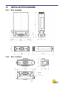
INSTALLATION DIAGRAMS.....................................................................
15.1
BOX MODULE.....................................................................
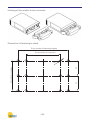
15.2
BUS MODULE.....................................................................
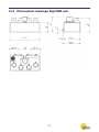
15.3
DIMENSIONAL DRAWINGS DIGI PBB UNIT.................................
DECLARATION OF CONFORMITY............................................................
ORDER CODES................................................................................
-4-
PAG. 88
PAG. 90
PAG. 90
PAG. 91
PAG. 92
PAG. 95
PAG. 95
PAG. 95
PAG. 97
PAG. 98
PAG. 99
-5-
1
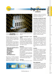
INTRODUCTION TO DIGICROWN PROBING LINE SYSTEM
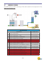
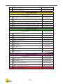
The DigiCrown is a flexible measuring system (from 1 to 372 sensors), configured
in networks (from 1 to 12) that can be connected to a PC via an RS232/USB serial
interface or dedicated RS485 interface cards for PCI or ISA bus.
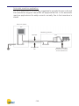
The diagram below shows the elements of the DigiCrown system in their possible
configurations. This user manual follows up the installation of the DigiCrown box
unit.
MARPOSS S.p.A. does not take on the obligation of notifying possible further
changes to the product.
The descriptions reported in this book do not authorize any tampering by nonauthorized personnel.
All names and logos of products and company are protected by copyright.
-6-
2
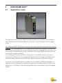
DIGICROWN BOX(C)
2.1
Application notes
The primary function of the DigiCrown box module is to acquire the measurement coming from the input sensor, to convert it, then linearize it into a digital
signal.
The Marposs LVDT digital pencil probes are automatically recognized by the box
module. The characteristics of the digital pencil probe are stored in its own memory, physically allotted into the Lumberg connector. Through its central pin, this
information is transferred from the connector to the EEPROM retentive memory
contained in the box module.
If an analog LVDT pencil probe is connected, the module detects the lack of
information. Anyway the unit can be configured with the range information and
sensitivity data, stored in the EEPROM retentive memory of the box module.
A version of the DigiCrown box module with an additional RAM is available, in
order to make it possible to expand the quantity of storable data to 9,000, thus
achieving a “buffering” of the sampling data to be transmitted to the managing
system.
-7-
The module includes a sine wave generator that transforms the external frequency from 75 KHz to 7500 Hz, for the management/control of the transducer.
A synchronization mechanism ensures the phase relationship between the two
frequencies, so the system is an “isofrequency” one.
The box module is assembled on the DigiCrown bus unit, by means of which the
communication with the data acquisition system with serial RS-485 standard is
carried out. The connection to the bus module is made by means of a 9-way sub
D-type connector that also supplies power to the box module.
Each box module, contains a LED for a quick diagnosis of the operating status
of the unit (see Chapter 3).
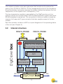
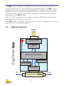
Internal structure
PENCIL PROBE
DigiCrown box
2.2
HW for the Analogue
measuring interface
A/D
MICRO
PROCESSOR
EE
RS-485
Sinusiodal
generator
Driver 485
DigiCrown bus
-8-
RS-485
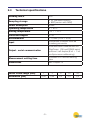
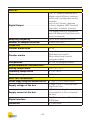
2.3
Technical specifications
Reading rate/s
250
Sampling storage
• 50 (standard version)
• 9000 (version with RAM)
Power absorption
40mA
Operating temperature
0 ÷ 60°C
Storing temperature
-20 ÷ +70°C
Protection degree
IP 43
Alimentazione
+7,5Vdc (-10% + 30%)
Input
connection to sensor via IP68
Lumberg connector
Output - serial communication
communication towards bus via
DigiCrown HW and RS485 serial
protocol, half duplex (8 bit + 1 bit
multiprocessor addressing)
Measurement settling time
consider a 20 minutes settling
time
Dimensions
see Chapter 15
Pencil Probe range (mm)
Resolution (μm)
1
2
5
10
20
0,05
0,05
0,2
0,2
0,5
-9-
3
DIGICROWN BOX(C) CH2
3.1
Application notes
The primary function of the DigiCrown box module two channels is to acquire the
measurement coming from the input sensor, to convert it, then linearize it into a
digital signal.
The Marposs LVDT digital pencil probes are automatically recognized by box
module with two channels. The characteristics of the digital pencil probe are stored in its own memory, physically placed into the Lumberg connector. Through
its central pin, this information is transferred from the connector to the EEPROM
retentive memory contained in the box module.
If an analog LVDT pencil probe is connected, the module detects the lack of
information. Anyway the unit can be configured with the range information and
sensitivity data, stored in the EEPROM retentive memory of the box module.
A version of the DigiCrown box module with an additional RAM is available, in
order to make it possible to expand the quantity of storable data to 9,000 (4.500
for each transducer), thus achieving a “buffering” of the sampling data to be
transmitted to the managing system.
- 10 -
The module includes a sine wave generator that transforms the external frequency from 75 KHz to 7500 Hz, for the management/control of the transducer.
A synchronization mechanism ensures the phase relationship between the two
frequencies, so the system is an “isofrequency” one.
The two channels box module is assembled on the DigiCrown bus unit, by
means of which the communication with the data acquisition system with serial
RS-485 standard is carried out. The connection to the bus module is made by
means of a 9-way sub D-type connector that also supplies power to the box
module.
Each box module, contains a LED for a quick diagnosis of the operating status
of the unit (see Chapter 3).
Internal structure
PENCIL PROBE
1
DigiCrown box
3.2
PENCIL PROBE
2
HW for the Analogue
measuring interface
1
2
A/D
MICRO
PROCESSOR
EE
RS-485
Sinuisodal
generator
Driver 485
DigiCrown bus
- 11 -
RS-485
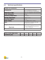
3.3
Technical specifications
Number of transducers
2
Reading rate
4000 samples per second
(two simultaneous transducers)
Sampling storage
up to 4500 samples for each transducer
Power absorption
90mA
Operating temperature
0 ÷ 60°C
Storing temperature
-20 to +70°C
Protection degree
IP 43
Power supply
+7,5Vdc (-10% + 30%)
Input
connection to sensor via IP68
Lumberg connector
Output - Serial communication
• Communication towards bus via Digi
Crown HW and RS485 serial protocol
• Up to 2083Kbps.
- Baud rate
Dimensions
Pencil Probe range (mm)
Resolution (μm)
see Chapter 15
1
2
5
10
20
0,05
0,05
0,2
0,2
0,5
- 12 -
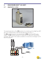
4
DIGICROWN BOX(C) 232 UNIT
4.1
Application notes
The typical application of the 232 module is the interfacing of the DigiCrown NET
with a PC equipped with an RS-232 standard serial port (Fig. 1).
The 232 module requires to be matched with a PSU unit for the NET power
supply. The 232 module embeds a 2m cable with a 9-way sub D-type female
connector. By means of this cable is possible to connect the unit straight in a PC
RS-232 serial port.
Solution with RS232
box box 232 psu
bus bus bus psc
- 13 -
The 232 module is fitted on the DigiCrown bus unit, by means of which the
communication with the data acquisition system takes place. The 232 module
supplies to the bus connector a square wave with a 75 KHz frequency, for the
generation of the sine wave that synchronizes the transducers. The connection
to the bus module is made via a 9-way sub D-type connector, which also supplies power to the 232 module.
Within the CPU integrated in the module, there is an EEPROM memory for the
management of the retentive-type data.
Each 232 module, moreover, contains a LED for a quick diagnosis of the operating status of the unit (see Chapter 3).
Internal structure
HOST
Driver 232
DigiCrown box
4.2
UART
MICROPROCESSOR
Sybchr. Gen.
EEPROM
Driver 485
RS-485
DigiCrown bus
- 14 -
RS-485
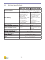
4.3
Technical specifications
Communication
1 RS232 full-duplex channel no
“handshake” (RTS/CTS), or alternatively “hardware handshake”
Port setting
• baud: 4800/ 9600 (de
fault)/ 19200/ 38400/ 57600/
115200 bit/sec
• bit number 8
• bit stop number 1
• parity EVEN
Bus interface
serial interface RS485 HalfDuplex
Power absorption
40mA
Operating temperature
0 ÷ 60°C
Storing temperature
-20 to +70°C
Protection degree
IP 43
Power supply
+7,5Vdc (-10% + 30%)
Input
RS232 9-way sub D-type female
connector
Dimensions
see Chapter 15
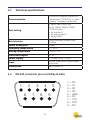
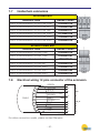
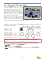
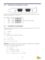
4.4
RS-232 connector pin-out (9-Way D-Sub)
1
2
6
3
7
4
8
5
9
- 15 -
1 = NC
2 = TX
3 = RX
4 = NC
5 = GND
6 = NC
7 = CTS
8 = RTS
9 = NC
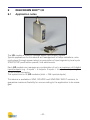
5
DIGICROWN BOX(C) USB UNIT
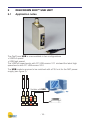
5.1
Application notes
The DigiCrown USB is now available in two configurations
• USB full speed
• USB high speed
The USB full speed works with PC USB version V1.1 mistead the latest high
speed works with PC USB version V2.0.
The USB module requires to be matched with a PSU unit for the NET power
supply (see figure 2).
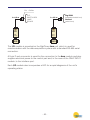
Solution with USB
box box USB psu
bus bus bus psc
- 16 -
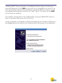
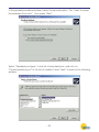
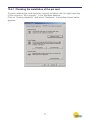
Installing QSPC, Easy Acquisition or the Marposs Driver Library, will allow the
automatic detection of the USB unit as soon as it’s plugged to the host PC. As
soon as Windows finds the new hardware connected, select the option “Install
the software automatically” and click on “Next” (fig. 3). The driver for the USB
unit will then be installed.
The software configuration of the USB module (using the MDHQSPC driver) is
done in the same manner as for the 232 unit.
Using the wizard it is possible to identify automatically the available COM port to
be plugged and to be used for the communication during the net configuration.
- 17 -
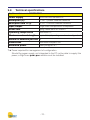
5.2
Technical specifications
USB FULL SPEED USB HIGH SPEED
Communication
Port setting
Bus interface
1 virtual COM channel with USB interface
(compatible with USB 1.1 / 2.0 standards)
• to activate the full
speed program a
baud higher than
9600 bit/sec
(19200 / 38400 / 57600
/ 115200 bit/sec)
• bit number 8
• bit stop number 1
• parity EVEN
Any programmed
baud active the maximum USB speed:
• 12Mbit/s if connected to a full speed
port
• 480Mbit/s if
connected to a high
speed port
serial interface RS485 Half-Duplex
Power absorption from bus 485
40 mA
90mA
Power absorption from usb
26 mA
Any absorption from
the usb
Operating temperature
0 ÷ 60°C
Storing temperature
-20 ÷ +70°C
Protection degree
IP 43
Power supply
+7.5Vdc (-20% +30%)
Input
Type “A” USB connector
Dimensions
see Chapter 15
- 18 -
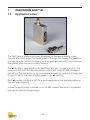
6
DIGICROWN BOX(C) AI
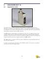
6.1
Application notes
The DigiCrown ai module has been developed for managing analog inputs
(tension or current) to the DigiCrown system. Through this module it is possible
to integrate in the network third-party sensors such as load cells, torque sensors,
flow-meters, pressure and humidity sensors.
The ai module is assembled on the DigiCrown bus unit, by means of which the
communication with the data acquisition system with serial RS-485 standard is
carried out. The connection to the bus module is made by means of a 9-way sub
D-type connector that also supplies power to the ai module.
Each ai module, contains a LED for a quick diagnosis of the operating status of
the unit (see chapter 4).
In order to avoid power overloads of the RS485 network, the sensor is powered
through an external voltage supply.
- 19 -
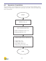
6.2
Sequence of operations
The connection of an analog sensor requires the wiring of the hardware and a
software configuration to define the input type, arm-ratio, offset and measuring
unit of the sensor.
START
WIRING (Par. 4)
SW CONFIGURATION
1 HW Configuration (Par. 5.1)
2 Addressing (Par. 5.2)
CONFIGURATION AI MODULE
1 - Input (Par. 6.1)
2 - Offset (Par. 6.2)
3 - Arm Ratio (Par. 6.2)
4 - Measuring Unit (Par. 6.2)
END
- 20 -
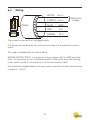
6.3
Wiring
WHITE
VINPUT+
ai
PURPLE VINPUTCABLE
BUS
BLUE
GND
RED
N.C.
GREEN
N.C.
}
Differential
voltage
The module comes with an unplugged cable.
The wiring must be done by the end-user according to the application requirements.
The cable is shielded with a metal braiding.
WIRING INSTRUCTIONS: to ensure the wiring complies with the EMC specifications, it is necessary to use a shielded connector. Make sure the metal braiding
of the cable is wired to the connector in all its entire surface (360°).
The maximum voltage between the input and the ground connector must be less
or equal to ±12,5 V.
- 21 -
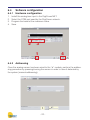
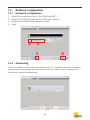
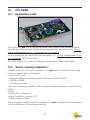
6.4
Software configuration
6.4.1
Hardware configuration
1.
2.
3.
4.
Install the analog box input in the DigiCrown NET.
Select the COM port used by the DigiCrown network.
Program the baud at the maximum value.
Save.
2
3
4
1
6.4.2
Addressing
Once the analog sensor has been wired to the “ai” module, perform the addressing procedure by pressing/moving the sensor in order to have it detected by
the system (manual addressing).
- 22 -
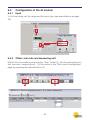
6.5
Configuration of the AI module
6.5.1
Input
In On-Line mode, set the range and the input type (see specifications at page
18).
1
2
6.5.2
Offset, arm ratio and measuring unit
Exit the On-Line mode by pressing the “Stop” button (1). Set the parameters (offset, arm ratio, measuring unit…) of the sensor in the “Edit current configuration”
page by pressing the relevant button (2).
2
1
- 23 -
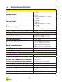
6.6
Technical specifications
INPUT
Voltage Input
± 10 V
±5V
0-10 V
(Input impedance >100KΩ)
Current Input
± 20 mA
4-20 mA
0-20 mA
(Input impedance > 23Ω)
Resistance Input
50...3000Ω
50...500Ω
(Measure current 3mA, 4 wires connection)
Measurement Bandwidth
Programmable from 5 to 750 Hz
OUTPUT
Voltage Resolution
0,02 mV - (range ± 5 V)
0,05 mV - (range ± 10 V)
Current Resolution
0,0001 mA
Resistance Resolution
0,1 Ω (range 50-3000 Ω)
0,01 Ω (range 50-500 Ω)
Serial communication
DigiCrown bus & protocol
Baud rate fino a 2083Kbps
Reading Speed
4000 sample/s
Buffer dimension
10450 sample/s
PERFORMANCE
Linearity
< 0.01% FSO
Voltage Gain Temperature Coefficient
70 ppm/°C
Current Gain Temperature Coefficient
106 ppm/°C
Offset (all ranges and input type, factory calibrated)
On the level of the noise
Voltage Offset Temperature Coefficient
23 ppm/FSO/°C
Current Offset Temperature Coefficient
110 ppm/FSO/°C
Warm Up Time
95% accuracy met after 5 minutes
from switch on
Calibration & Measurement Accuracy
Gain and offset for all input type
- 24 -
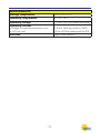
ENVIRONMENTAL
Storage Temperature
-20 °C to + 70°C
Operating Temperature
0 °C to +60 °C
Operating Voltage
+ 7,5 VDC (-10%+30%) (powered from the Bus)
Operating Current
• Voltage, current and resistance conf
• 4-20 mA conf
100 mA (with light load on VEXT)
150 mA (with 20mA powering sensor from VEXT)
Interface
Digi Crown Network
- 25 -
7
DIGICROWN BOX(C) EI
7.1
Application notes
The DigiCrown ai module has been developed for managing analog inputs
(tension or current) to the DigiCrown system. Through this module it is possible
to integrate in the network third-party sensors such as load cells, torque sensors,
flow-meters, pressure and humidity sensors.
The ei module is assembled on the DigiCrown bus unit, by means of which the
communication with the data acquisition system with serial RS-485 standard is
carried out. The connection to the bus module is made by means of a 9-way sub
D-type connector that also supplies power to the ei module.
Each ei module, contains a LED for a quick diagnosis of the operating status of
the unit (see chapter 4).
In order to avoid power overloads of the RS485 network, the sensor is powered
through an external voltage supply.
- 26 -
7.2
Sequence of operations
The connection of an analog sensor requires the wiring of the hardware and a
software configuration to define the input type, arm-ratio, offset and measuring
unit of the sensor.
START
WIRING (Par. 4)
SW CONFIGURATION Sw (par. 5)
CONFIGURATION EI MODULE
END
- 27 -
Wiring
PURPLE
WHITE
BLACK
RED
GREEN
BROWN
BLUE
GREY
YELLOW
ei
7.3
CABLE
BUS
1
A-
2
A+
3
GND
4
+5
5
ER-
6
Z-
7
Z+
8
B-
9
B+
CASE
The module comes with an unplugged cable.
The wiring must be done by the end-user according to the application requirements.
The cable is shielded with a metal braiding.
WIRING INSTRUCTIONS: to ensure the wiring complies with the EMC specifications, it is necessary to use a shielded connector. Make sure the metal braiding
of the cable is wired to the connector in all its entire surface (360°).
- 28 -
7.4
Software configuration
7.4.1
Hardware configuration
1.
2.
3.
4.
Install the analog box input in the DigiCrown NET.
Select the COM port used by the DigiCrown network.
Program the baud at the maximum value.
Save.
2
3
4
1
7.4.2
Addressing
Once the analog sensor has been wired to the “ai” module, perform the addressing procedure by pressing/moving the sensor in order to have it detected by
the system (manual addressing).
- 29 -
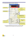
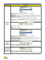
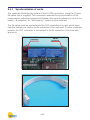
7.5 Incremental digital encoder unit form
Incremental Digital Encoder Unit Form in On-Line mode
(example for On-Line Operative mode, maximized format)
- 30 -
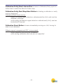
Calibration/Verify/Abort choose Box let select a Calibration/Verify cycle for
further start or select the Abort for further stop.
Calibration/Verify Start/Stop/Abort Button let starting a calibration or verify
cycle or stopping it.
Calibration/Verify Cycle can be:
single (1st Marker signal detection calibrates/verifies Unit), and must be
stopped or aborted
never-ending (all Markers signal detection calibrate/verify Unit), and can
be aborted if required
Calibration Reset Button let erase immediately zeroings on Unit, forcing its
state to not calibrated.
If Marker signal is programmed OFF ( not provided):
single calibration and verify are immediate
never-ending calibration and verify are not supported
- 31 -
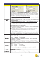
7.5.1 Measure panel
Measure Panel image explanation
Unit in transitory
Input not jet acquired.
Encoder not calibrated.
Unit in transitory
Input not jet acquired.
Encoder calibrated.
Unit in alarm
Encoder not connected
Encoder Phase-A , Phase-B , Marker signal
wrongly connected.
Encoder Alarm or Over-Speed.
Unit is properly working in not calibrated state
Encoder not calibrated.
Unit is properly working in not calibrated state
Encoder not calibrated , calibration cycle
pending.
Unit is properly working in calibrated
state
Encoder calibrated, calibration done with
success.
Measure in range.
Unit is properly working in calibrated
state
Encoder calibrated , verify cycle pending.
Measure in range.
Unit is properly working in calibrated
state
Encoder calibrated , calibration verify done
with success (match).
Measure in range.
- 32 -
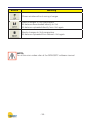
Unit is properly working in calibrated
state
Encoder calibrated , calibration verify done
with error (unmatch).
Measure in range.
Unit is properly working in calibrated
state
Encoder calibrated, no verify information
available.
Measure in range.
Unit is working with over-range warning
Encoder calibrated.
Measure out of range.
Unit is working with over-range warning
Encoder not calibrated .
Measure out of range.
- 33 -
7.5.2 Read/Write Incremental Digital Encoder Unit Parameters
This button opens a dedicated new form for reading or writing the
Unit parameters. All data are uploaded directly from Unit and, on
modify, downloaded directly into Unit.
Sensor Type Parameter let choose between 4 available acquisition modes:
•
Linear
[mm]
•
Rotary
[degrees]
•
Periodic
[degrees with 360° module]
•
Counter
[no unit as default , unit programmable as required]
Parameter Form behaviour depends on Sensor Type Parameter programmed
value.
Digital Encoder
Unit Linear
Parameters Form
Digital Encoder
Unit Rotary [degrees]
Parameters Form
- 34 -
Digital Encoder
Unit Periodic [degrees]
Parameters Form
Parameter
Sensor
Type
Digital Encoder
Unit Counter
Parameters Form
Meaning
Linear: Signed measure [mm], based on Step parameter applies to Linear Encoder and produces a measure with dimensional attribute, that can overflow.
Rotary: Signed angular measure [degrees], as ±360°*Round,
based on Line-Count parameter.
Applies to Rotary Encoder and produces a ±360°*Round measure with degree attribute, that can overflow.
Periodic: Signed angular measure [degrees], module(360°),
based on Line-Count parameter.
Applies to Rotary Encoder and produces a module (360°) measure with degree attribute, that never overflows.
Counter: Signed counting.
Applies to Linear Encoder, Rotary Encoder or any kind of other
Incremental Digital Devices, and produces a measure with no
attribute, that can overflow.
- 35 -
Parameter
Meaning
Quadrature: Phase-A and Phase-B in quadrature
Phase A+: Phase-A only incrementing counting Phase-B not cared
Phase B+: Phase-B only decrementing counting Phase-A not cared
Phase A+ Phase B-: Phase-A incrementing counting
Phase-B decrementing counting
Phase A+/- Phase B Dir: Phase-A incrementing/decrementing
counting function of Phase-B level
Connection
Type
x1: Division none
x2: Division half step
x4: Division quarter step
Differential TTL: Differential signals with TTL levels.
Single Ended TTL: Single Ended signals with TTL levels.
Complementary HTL: Complementary signals with HTL levels.
Single Ended HTL: Single Ended signals with HTL levels.
Step
(Linear mode only) Encoder Step [μm], default 1 [μm]:
measure resolution is self-adjusted by Unit elaborating this value.
Line Count
(Rotary and Perioduc modes only) Encoder Impulses/Round , default 3600:
measure resolution is self-adjusted by Unit elaborating this value.
- 36 -
Parameter
Frequency
Max
Marker
Alarm
HW
Direction
Meaning
Encoder/Counter Maximum Frequency [kHz], default disabled.Maximum Frequency of Input Signal parameter optionally
specifies maximum operating frequency of Incremental Digital
Encoder or other Incremental Digital Device:
• Maximum Speed [mm/s] / Step [mm/1000] for Linear Encoder,
metric system
• Maximum Speed [inch/s] / Step [inch/1000] for Linear Encoder,
imperial system
• Maximum Speed [RPM] / 60000 * Step [Impulses/Round] for
Rotary Encoder
If enabled , Maximum Frequency of Input Signal parameter
restricts allowed input frequencies:
1) On single Phase-A,B signals, transitions above programmed
frequency are filtered.
2) On both Phase-A,B signals, concurrent transitions above
programmed frequency are detected and notified via
<Over Speed> alarm.
So Maximum Frequency of Input Signal parameter optionally let
filter spikes on single phase and detect over-speed conditions.
Marker signal present
- ON
Phase-M provided
- OFF Phase-M not provided
If Phase-M (Marker) is declared as present, test on its proper
connection is enabled.
If Phase-M (Marker) is declared as present, it will be used for
Marker cycles in order to calibrate and apply zeroing to system.
Alarm signal present
- ON
Alarm
provided
- OFF Alarm
not provided
If Alarm is declared as present, test on its level is enabled:
on error, alarm <Transducer Not Operative> is asserted.
Direction of counting
- forward
incrementing counting
- backward
decrementing counting
- 37 -
Button
Meaning
Closes window without saving changes.
Saves changes to Unit parameters.
All data are downloaded directly to Unit.
All data are uploaded directly from Unit again
Aborts changes to Unit parameters.
All data are uploaded from Network Unit again.
NOTE:
For all the error codes refer at the MDHQSPC software manual.
- 38 -
7.6
Technical specifications
INPUT
Single ended (A, B, Z, ER) or
Square wave signal connection......... Differential (A+, A-, B+, B-, Z+,
Z-, ER+,ER-)
Input signal type....................................
TTL, HTL, RS422, push-pull, or
open-collector
In phase (A)
Input channel..........................................
In quadrature (B)
Reference (Z)
Error (ER)
(V+ is defined as the voltage of
the terminals A+, B+ Z+, ER+)
Switching levels.....................................
(V- is defined as the voltage of the
terminals A-, B- Z-, ER-)
(Vdiff is the differential voltage
between the inputs V+ e V-)
High when Vdiff > 0.6 V
Input type set as Differential..............
Tipo di ingresso impostato su Single Ended...
Low when Vdiff < -0.6 V
(Vdiff is the differential voltage
between the inputs V+ e V-)
High when V+ input >2.4 V
Low when V+ input <1 V
Frequenza dei segnali di fase all’ingresso... Maximum 3 MHz
Alarm disconnect the cable (single cable) or short-circuit between V+ and V-.
Test sui segnali in ingresso................ Over speed alarm
Transducer failure alarm
(if present in the encoder)
- 39 -
OUTPUT
The “ei” module supplies as a
digital output different measurement units (configurable via the
module):
mm or inch (linear), degrees
Digital Output.......................................... (rotary), degrees [360° module]
(periodic), numbers (counter).
The digital output is compatible
with the Marposs DigiCrown prrotocol commands.
Sampling frequency.............................. Up to 4000 samples/second
Number of samples buffered.............. maximumu 6200
COUNTER
Counter dimensions.............................. 32 bit
In quadrature
Bi-directional counter
Counter modes.......................................
Mono-directional counter
(programmable)
Interpolation............................................ X1, X2, X4 (programmable)
ENVIRONMENTAL PARAMETERS
Storing temperature.............................. -20°C to +70°C
Operating temperature......................... 0°C to +60°C
Protection degree.................................. IP43
ELECTRIC INTERFACE
Encoder supply voltage and maximum current... 5.1Vdc (+/-4%) max 500mA
Supply voltage of the box....................
7,5Vdc (-10% + 30%) da from
DigiCrown bus
100mA (excluding the current
Supply current of the box.................... consumption of the connected
sensor)
Digital interface......................................
DigiCrown maximum Baud rate
2083Kpbs
Connector...............................................
9 D-sub male
- 40 -
7.7
Heidenhain extensions
WITH RING NUT
DESCRIPTION
ORDER CODES
PROL.X HEIDENHAIN 12S GH. EMI 0.5MT
6739957016
PROL.X HEIDENHAIN 12S GH. EMI 2MT
6739957020
PROL.X HEIDENHAIN 12S GH. EMI 5MT
6739957017
PROL.X HEIDENHAIN 12S GH. EMI 10MT
6739957018
PROL.X HEIDENHAIN 12S GH. EMI 15MT
6739957010
PROL.X HEIDENHAIN 12S GH. EMI 20MT
6739957019
WITHOUT RING NUT
ORDER CODES
DESCRIPTION
PROL.X HEIDENHAIN 12S EMI 0.5MT
6739957015
PROL.X HEIDENHAIN 12S EMI 1.5MT
6739957021
PROL.X HEIDENHAIN 12S EMI 3MT
6739957024
PROL.X HEIDENHAIN 12S EMI 5MT
6739957012
PROL.X HEIDENHAIN 12S EMI 10MT
6739957013
PROL.X HEIDENHAIN 12S EMI 15MT
6739957005
PROL.X HEIDENHAIN 12S EMI 20MT
6739957014
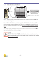
7.8
Electrical wiring 12 pins connector of the extension
CABLE
GREEN
YELLOW
WHITE
BLACK
BROWN
GREY
PURPLE
BLUE
RED
PINK
GREY
CASE
For other connection needs, please contact Marposs.
- 41 -
1
A-
2
A+
3
GND
4
5V
5
EXE_AL
6
M-
7
M+
8
B-
9
B+
8
DIGICROWN BOX(C) I/O
8.1
Application notes
The I/O module is used to manage digital input/output signals.
Typical applications for this device are management of lamp indications, solenoid valves (through power relays) or acquisition of input signals by local cycle
START/STOP push-button panels, limit switches,etc.
Each I/O module can manage any combination of up to a maximum of 8 digital
inputs/outputs (e.g.: 4 inputs + 4 outputs, 2 inputs + 6 outputs, etc.), using a
15-pin D-sub connector.
The system limit is 32 I/O modules (total = 256 inputs/outputs).
This device is available in SINK, SOURCE and SINK ONLY INPUT versions, to
guarantee maximum flexibility for use according to the application to be managed.
- 42 -
Ext. +24Vdc
L=0,5 m
{
PLC
SWITCH BOX
LAMP
RELAYS
L=2,5 m
I/O
I/O
SINK
SOURCE
ONLY
INPUT
BUS
BUS
{
Digi PBB
(integrated switch box)
General
(switch box)
The I/O module is mounted on the DigiCrown bus unit, which is used for
communication with the data acquisition system with a standard RS-485 serial
connection.
A 9-pin D-sub connector is used for the connection to the bus module and also
supplies electrical power to the control part and, in the case of the ONLY INPUT
module, to the interface part.
Each I/O module also incorporates a LED for a rapid diagnosis of the unit’s
operating status
- 43 -
i/o
Electrical connections
CAVO
BUS
BIANCO
VIOLA
GIALLO
VERDE
CELESTE
GRIGIO
BLU
ROSA
MARRONE
NERO
ARANCIONE
ROSSO
1
B0
2
B1
3
B2
4
B3
5
B4
6
B5
7
B6
8
B7
9
GND
Connettore 15 poli maschio
2
1
9
3
4
5
6
7
8
10 11 12 13 14 15
10 GND
14 +V10
15 +V10
{
8.2
N.C. per modulo I/O “ONLY INPUT”
CASE
Pins 1 - 8 of the 15-pin male D-sub connector are used to connect the I/O module to external signals.
Pins 9 - 10 and 14 - 15 are used to supply the 24V dc to the interface part. The
electrical power supply is divided over four pins to guarantee an optimum current flow. To avoid overloads on the wires the 24V dc must be wired on all four
pins.
The power supply voltage on the 15-pin D-sub connector must be of the SELV
type and isolated from the bus voltage.
NOTE:
For the “ONLY INPUT” I/O module the electrical connections are the
same, except there is no 24V dc power supply. Therefore, pins 14 and
15 are not connected.
- 44 -
8.3
Input/Output configuration
To configure the inputs/outputs on the DigiCrown I/O module you must install
one of the following pieces of software: QSPC, Easy Acquisition or Marposs
Driver Library.
Below are the basic steps for I/O module set-up.
For further information about the MDHQSPC driver, consult manual available on
our web site: www.testar.com.
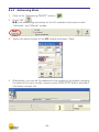
8.3.1
Off-Line mode
1.
Create a new NET by selecting the type of interface with the management
PC: isa, pci card or 232/USB module.
2.
Select the I/O unit by clicking on the relative button (
sert” to insert the I/O modules present in the NET.
3.
Finally, press “Save” to save the current NET, and “Apply” to activate the
configuration.
- 45 -
), and press “In-
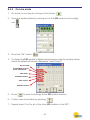
8.3.2
Addressing Mode
1.
Click on the “Addressing ON/OFF” button (
2.
Press “OK” (
).
N.B.: the addressing procedure for the I/O modules is the same in both
“Automatic” and “Manual” modes.
3.
Type in the serial number of the I/O module and press “Save”.
4.
Alternatively, you can set the address for the module by physically changing
the status of an input; usually: press a cycle START/STOP button, activate a
limit switch contact, etc.
- 46 -
).
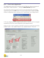
8.3.3
On-Line mode
1.
Go to the on-line step by clicking on this button:
2.
Open the window below by clicking on the first I/O module to be configured:
.
.
3.
Press the “Db” button:
4.
Configure the I/O module’s digital inputs/outputs using the window shown
below. By default all bits are enabled as “Input/Output”.
.
BIT NOT USED
BIT ENABLED AS BOTH
INPUT AND OUTPUT
ONLY INPUT
INGRESSO NEGATO
ONLY OUTPUT
NEGATED OUTPUT
5.
Press
to save the settings to the I/O module memory.
6.
Finally, close the window by pressing:
7.
Repeat steps 2 to 6 for all of the other I/O modules in the NET.
- 47 -
.
8.3.4
Flow-Control Application
The digital input/output driver interfaces with the Marposs data processing software (QSPC, Easy Acquisition…) using the Flow-Control application.
This application allows a specific function to be associated with each digital
signal arriving from the I/O module. To avoid conflicts with the DigiCrown I/O
module configuration driver, set each bit to “Input/Output” (see image below).
In this way assignment of the digital inputs/outputs of each bit will be managed
completely by the Flow-Control application (see example below).
If there are two or more modules in the NET, the bits are numbered sequentially:
module 1 (bits 1 - 8), module 2 (bits 9 - 16), module 3 (bits 17 - 24), etc.
- 48 -
8.4
DigiCrown “PBB” push button
The DigiCrown pbb push button implements the I/O unit, allowing to control
eight digital inputs by means of ON/OFF
buttons and a four positions selector.
Typically the buttons are used for START/
STOP sequences and data acquisitions,
while the selector for setting a different
working piece to be measured.
Besides the 15-pin female D-sub port
used for connecting the I/O (ONLY INPUT) module, the push button includes a
9-pin female connector for linking an external footswitch.
It follows the frontal view of the Digi pbb push button with the relevant digital bit
associated to each switch.
• Button 1 = bit 0
• Button 2 = bit 1
• Button 3 = bit 2
• Button 4 = bit 3
• Selector position A = bit 7
• Selector position B = bit 6
• Selector position C = bit 5
• Selector position D = bit 4 (*)
(*) The bit 4 reserved to the “D” position of the selector, it’s automatically
assigned to the footswitch by unscrewing the 9-pin male connector.
The following MARPOSS footswitches are compatible with the push button:
• Quick Read footswitch (code 6738099030)
• E4N footswitch (code 6738099015)
• E9066 footswitch (code 6131600810) – the adapter (code 4701300042) is
required.
- 49 -
8.5
Technical specifications
DigiCrown I/O (SINK version) / code 767I000000
Power supply (bus)
+7,5Vdc (-10% + 30%)
Current absorption (bus)
40mA
Power supply (V I/O)
24Vdc (± 20%)
Current absorption (I/O)
15mA (no output active)
I/O size
8 input and/or output bits, optoisolated, individually selectable
Input specifications
Voff (min): V I/O - 5V; Von (max): V I/O - 15V
OUT capacity
200mA (per OUT)
- outputs total max. current: 800mA (temp.=0 to +50°C)
- outputs total max. current: 700mA (temp.=0 to +60°C)
I/O protection
power supply inversion, output overload
DigiCrown I/O (SOURCE version) / code 767I010000
Power supply (bus)
+7,5Vdc (-10% + 30%)
Current absorption (bus)
40mA
Power supply (V I/O)
24Vdc (± 20%)
Current absorption (I/O)
25mA (no output active)
I/O size
8 input and/or output bits, optoisolated, individually selectable
Input specifications
Voff (max): 5V; Von (min): 15V
OUT capacity
200mA (per OUT)
- outputs total max. current: 800mA (temp = 0 to +50°C)
- outputs total max. current: 700mA (temp.= 0 to +60°C)
I/O protection
power supply inversion, output overload
DigiCrown I/O (ONLY INPUT version) / code 767I020000
Power supply (bus)
+7,5Vdc (-10% + 30%)
Current absorption (bus)
50mA (all inputs activated)
I/O size
8 input bits (not isolated)
Input specifications
OFF: Rswitch > 500 KΩ
ON: Rswitch < 3300 Ω
CAUTION:
Use a SELV power source (as defined by EN60950)
- 50 -
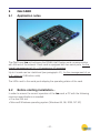
9
ISA CARD
9.1
Application notes
The DigiCrown isa unit achieves the RS485 Half Duplex serial communication
with the rest of the network. Each card is equipped with two serial ports, for the
overall management of 31 + 31 sensors or I/O modules.
Up to 4 cards can be interlinked (see paragraph 4.1), for the management of up
to 8 networks (248 active units).
The LEDs next to the serial ports display the operating status of the card.
9.2
Before starting installation…
In order to ensure the correct operation of the isa card, a PC with the following
minimum specifications is needed:
• One free ISA slot
• Microsoft Windows operating system (Windows 95, 98, 2000, NT, XP)
- 51 -
9.2.1
Installing the ISA card on a standard PC
Use the installation procedure described in the following chapter (CARD Setup).
Windows provides a vast number of addresses for the system, we suggest using
those indicated below, which should usually be included among the available
resources.
Cards
Card 1
Card 2
COM
ADDRESS
IRQ
COM a
0100
10
COM b
0108
11
COM c
0110
5
COM d
0118
7
The most critical resource may be the interrupt value, especially in the case of
two
cards. Therefore, in this case, interrupts 5 and 7 may be at risk. If so, it is best to
disable the device that is not in use (for example the BIOS parallel port), and
designate the required available interrupts as LEGACY ISA.
9.2.2
Installing the ISA card in a Marposs E9066N industrial PC
MARPOSS SpA supplies the ISA cards with a series of default address and
interrupt settings, as indicated in the below table:
Cards
Card 1
COM
ADDRESS
IRQ
COM a
(*) 0100
(*) 10
COM b
(*) 0108
(*) 11
To simply installation on Marposs Industrial PCs, the company supplies all
E9066N systems with the following default BIOS settings:
interrupt 10
LEGACY ISA
interrupt 11
LEGACY ISA
As the addresses 0100 and 0108 are normally free, these pre-settings help to
simplify the installation procedure (there is no need to move any jumpers on the
card) and all the user has to do is select the suggested values (*) when carrying
out the COM installation procedure on the E9066N (see chapter 3 CARD Setup).
- 52 -
9.3
Card setup
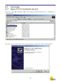
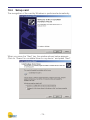
9.3.1
Setup of PC for housing the isa card
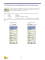
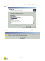
Click on “Start” Î “Settings” Î “Control panel”and double-click on “Add/Remove Hardware”.
As soon as the window shown below appears, press the “Next” pushbutton.
- 53 -
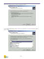
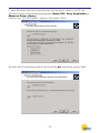
Select the “Add a device” option and press “Next”
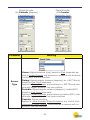
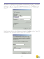
In the following window, select “Add a new device” in the list of devices, and
press “Next”.
- 54 -
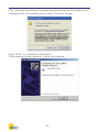
In the guided-procedure window, select the second option, “No, I want to select
the hardware from a list” , then press “Next”.
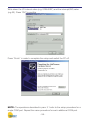
Select “Standard port types” in the list of manufacturers, and click on
“Communications port” in the list of models. Press “Next” to pass to the following
window.
- 55 -
In the window shown below, select the option “Ports (COM & LPT)” , then press
“Next”.
Should the warning message shown below appear, click on “OK”.
- 56 -
Set a basic configuration value that does not produce any conflict in the system,
making sure that the “No conflicts” message appears in the “Conflicting device
list” box (e.g. “Basic configuration 0005”). Then double-click on “IRQ/Interrupt
Request”.
Enter the interrupt-level value that you wish to set for the isa card (e.g. Value 03),
making sure that there is no conflict. Press “OK” to confirm.
- 57 -
Write down the I/O interval value (e.g. 02E8-02EF) and the interrupt/IRQ value
(e.g.03). Press “OK” to confirm.
Press “Finish” in order to complete the setup and switch the PC off.
NOTE: The operations described in para. 3.1 refer to the setup procedure for a
single COM port. Repeat the same procedure for each additional COM port.
- 58 -
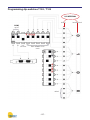
9.3.1
Programming the isa card “dip-switches”
Once the card addressing procedure has been completed, it is necessary to
define the following values by programming the dip-switches:
1.
The I/O interval start value (e.g.: 0100).
IMPORTANT: position ON = Ø.
In this case, the following dip-switches are used:
T102 and T103 Î COM a Î which communicates via connector J1
T102 and T106 Î COM b Î which communicates via connector J2
2.
The interrupt value.
IMPORTANT: to select the interrupt, set only the corresponding dip-switches
to ON. All the other dip-switches must be set to OFF.
In this case, the following dip-switches are used:
T101 Î INTERRUPT CHA Î COM a (which communicates via connector J1)
T104 Î INTERRUPT CHB Î COM b (which communicates via connector J2)
When setting the dip-switches it is important to bear in mind that each hexadecimal digit must be converted into 4 binary digits for use in the programming
procedure illustrated in the diagram.
- 59 -
Programming dip-switches T102 / T103
I/O INTERVAL
binary
COM
on/off
Not used
Basic address for all
cards
default
- 60 -
hexadecimal
Programming dip-switches T102 / T106
I/O INTERVAL
binary
COM
on/off
Not used
Basic address for all
cards
default
- 61 -
hexadecimal
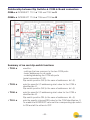
In order to simplify this operation, and reduce the risk of errors to a minimum, a
“CONFIGURATOR” is provided in Excel format that allows the user to define the
position of the dip-switches graphically, based on the hexadecimal values defined using the Windows installation procedure.
How to interpret the graphic configurator with reference to the card…
- 62 -
Relationship between Dip Switchs Î COM Î Board connectors
COM a Î INTERRUPT T101 Î T103 and T102 Î J1
COM b Î INTERRUPT T104 Î T106 and T102 Î J2
Summary of isa card dip-switch functions
• T102 Î
used for:
- settings that are common to the two COM ports
- basic addresses for all cards
- enabling/disabling the COM a/b ports
(serial connectors J1/J2)
Dip-switch position ON (in the case of addresses: bit=0)
• T103 Î
sets the specific I/O addressing start value for the COM a
identified as J1.
Dip-switch position ON (in the case of addresses: bit=0)
• T106 Î
sets the specific I/O addressing start value for the COM a
identified as J2.
Dip-switch position ON (in the case of addresses: bit=0)
• T101 Î
sets the specific interrupt/IRQ value for the COM identified as J1.
To enable the INTERRUPT value set the corresponding dip-switch
to ON and all the others to OFF.
- 63 -
• T104 Î
sets the specific interrupt/IRQ value for the COM identified as J2.
To enable the INTERRUPT value set the corresponding dip-switch
to ON and all the others to OFF.
N.B.:
• T101 + T104 must not have the same interrupt enabled.
• If a COM (a or b) is disabled (by setting the corresponding position on T102),
set all the corresponding INTERRUPT dip-switches to OFF in order to free this
resource on the BUS and make it available to other devices.
Example:
COM a disabled
T102 Î dip switch CHA set to OFF
T101 Î all dip-switches set to OFF
or
COM b disabled
T102 Î dip switch CHB set to OFF
T104 Î all dip-switches set to OFF
- 64 -
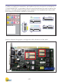
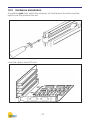
9.4
Installation of ISA card in the pc
When you have completed the procedure for the configuration of the dip-switches
of the isa card, install the device in the PC. Switch the computer off, and remove
the frame and the metal cover that protects the slot.
Insert the card in a free ISA slot.
- 65 -
9.4.1
Synchronization of cards
The cards are interlinked by means of the OUT-IN connectors, using the 10-pins
flat cable that is supplied. This connection extends the synchronization of the
measurement reference frequencies between the various networks to up to 4 isa
cards (=8 networks). An “isofrequency” system is thus obtained.
The flat cable must be connected to the OUT connector of a card, which becomes the master one, and to the IN connector of the next card. If further cards are
present, the OUT connector is connected to the IN connector of the third one,
and so on.
OUTPUT
Connector
INPUT
Connector
- 66 -
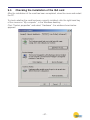
9.5
Checking the installation of the ISA card
After the installation of the card has been completed, close the cover and restart
the PC.
To check whether the card has been correctly installed, click the right-hand key
of the mouse on “My computer”, in the Windows desktop.
Click “System properties” and select “Hardware”: the window shown below
appears.
- 67 -
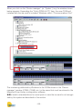
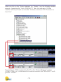
When you click on the “Device manager” (or “System”) key, the window shown
below appears. Expanding the “Ports (COM & LPT)” item, the new COM port
installed with the isa card is included: Windows calls it “Communications Port”.
The numbering attributed by Windows to the COMs shown in the “Device
manager” window (COM5, COM6, etc.) is the same that must be entered in the
Marposs Driver Library configuration software.
N.B.: Install a standard driver for serial ports in case the isa card is not recognized by the system as described in this section.
- 68 -
9.6
Connection of networks to cards
The connection of the networks is made by means of an RS-485 serial cable,
directly to connectors “J1” and “J2”.
The cables come in the following lengths:
•
2mt
code 6738057016
•
10mt code 6738057023
•
15mt code 6738057022
•
25mt code 6738057017
}
9.7
WITH power supply
Calculation of absorption
To calculate the total absorption of the card and networks from the +5 V of the
ISA slot, consider:
VNETWORK = 7,5Vdc
PCARD = 1,5W
K = 1,25 (efficiency of DC/DC converter)
INETWORK = IMODULES x NMODULES
PNETWORK = VNETWORK x INETWORK
PTOTAL ABSORBED = PNETWORK x K + PCARD
Example: the example shown below is specific for a DigiCrown configuration
with a maximum RS-485 cable length of 10 m.
NMODULES = 31 + 31 = 62
IMODULES = 0,04A
INETWORK = 62 x 0,04 = 2,48A
PNETWORK = 7,5 x 2,48 = 18,6W
PTOTAL ABSORBED = 18,6 x 1, 25 + 1,5 = 24,75W
- 69 -
9.8
Technical specifications
DigiCrown isa - code 6355322000
Power supply
from ISA bus standard 5V
Absorption (P)*
1.5W + power towards networks
Absorption from +5 (I)
0,2 A + current towards networks
Input/Output
DigiCrown HW&protocol compatible
RS485 rate
prog. Baud 9600 or 208333
Operating temperature
standard PC
Maximum network length
up to 1 Km (depending on network configuration)
Number of networks per card 2
Dimensions
standard compact ISA
Absorbed power
vedi paragrafo 9.7
* Î Power required for management of configuration.
Should the power supply unit integrated in the PC not be able to supply this
power, a DigiCrown psu+psc module must be installed.
- 70 -
10
PCI CARD
10.1
Application notes
The DigiCrown pci unit achieves the RS485 Half Duplex serial communication
with the rest of the network. Each card is equipped with two serial ports, for the
overall management of 31 + 31 sensors or I/O modules.
Up to 6 cards can be interlinked (see paragraph 3.1), for the management of up
to 12 networks (372 active units).
The LEDs next to the serial ports display the operating status of the card.
10.2
Before starting installation…
In order to ensure the correct operation of the pci card, a PC with the following
minimum specifications is needed:
• One free PCI slot
• Microsoft Windows operating system (Windows 2000, NT, XP)
• 128 MB of RAM
• 700 MHz processor
One of the following programs, which can be ordered separately, must be installed in
the PC:
• Quick SPC (release 2.2)
• Easy Acquisition (release 2.2)
• Marposs Driver Library
These programs enable the PC to recognize the pci card with the system drivers
for the installation of the peripheral device.
- 71 -
10.3
Hardware installation
To install the pci card, switch the computer off, and remove the frame and the
metal cover that protects the slot.
Insert the card in a free PCI slot.
- 72 -
10.3.1 Synchronization of cards
The interlinking of the cards is achieved by means of the OUT-IN connectors,
using the 10-pins flat cable that is supplied. This series connection, besides
extending the configuration of the network to up to 6 pci cards (=12 networks),
ensures the synchronization of the measurement reference frequencies in the
various networks. An “isofrequency” system is thus obtained.
The flat cable must be connected to the OUT connector of a card, which becomes the master one, and to the IN connector of the next card. If further cards are
present, the OUT connector is connected to the IN connector of the third one,
and so on.
OUTPUT
Connector
INPUT
Connector
- 73 -
10.4
Setup card
The recognition of the card by Windows is performed automatically.
When you press the “Next” key, the window shown below appears.
Click on “Search for a suitable driver for my device” and press “Next”.
- 74 -
In case Windows does not automatically find the driver, insert in the PC the
CD-Rom of one of the following programs: Quick SPC, Easy Acquisition or
Marposs Driver Library.
Click on the “CD-ROM drives” options, then press “Next”.
As soon as the operating system has found the pci card driver, press “Next”.
- 75 -
If the “Windows Logo testing” message pops-up saying that the software is not
compatible with the operating system, press “Continue Anyway”.
Press “Finish” to complete the installation.
If the operating system requests it, restart the computer.
- 76 -
10.4.1 Checking the installation of the pci card
To check whether the card has been correctly installed, click the right-hand key
of the mouse on “My computer”, in the Windows desktop.
Click on “System properties” and select “Hardware”: the window shown below
appears.
- 77 -
When you click on the “Device manager” (or “System”) key, the following window
appears. Expanding the “Ports (COM & LPT)” item, the new pair of COMs
installed with the pci card are included: Windows calls them “PCI Communications Port”.
The number of COMs assigned by the PC in the “Device Manager” window
(COM5, COM6, etc.) is the same that must be entered in the “MDHQSPC” configuration software.
- 78 -
10.4.2 Connection of networks to cards
The connection of the networks is made by means of an RS-485 serial cable,
directly to connectors “J1” and “J2”.
The cables come in the following lengths:
•
2mt
code 6738057016
•
10mt code 6738057023
•
15mt code 6738057022
•
25mt code 6738057017
}
10.5
WITH power supply
Calculation of absorption
To calculate the total absorption of the card and networks from the +5 V of the
PCI slot, consider:
VNETWORK = 7,5Vdc
PCARD = 1,5W
K = 1,25 (efficiency of DC/DC converter)
INETWORK = IMODULES x NMODULES
PNETWORK = VNETWORK x INETWORK
PTOTAL ABSORBED = PNETWORK x K + PCARD
Example: the example shown below is specific for a DigiCrown configuration
with a maximum RS-485 cable length of 10 m.
NMODULES = 31 + 31 = 62
IMODULES = 0,04A
INETWORK = 62 x 0,04 = 2,48A
PNETWORK = 7,5 x 2,48 = 18,6W
PTOTAL ABSORBED = 18,6 x 1, 25 + 1,5 = 24,75W
- 79 -
10.6
Technical specifications
DigiCrown pci - code 6355321000
Power supply
from PCI bus standard 5V
Absorption (P)*
1.5W + power towards networks
Absorption from +5 (I)
0,2 A + current towards networks
Input/Output
DigiCrown HW&protocol compatible
RS485 rate
prog. Baud 9600 or 208333
Operating temperature
standard PC
Maximum network length
up to 1 Km (depending on network configuration)
Number of networks per card 2
Dimensions
standard compact PCI
Absorbed power
vedi paragrafo 10.5
* Î Power required for management of configuration.
Should the power supply unit integrated in the PC not be able to supply this
power, a DigiCrown psu+psc module must be installed.
- 80 -
11
NETWORK POWER SUPPLY UNIT
11.1
Application notes
The DigiCrown psu unit is formed of a stabilized power supply unit and an
interface module to be connected to the network in the first module position.
The psu unit supplies the required electric power, as reported on the Technical
Specification.
The connection of the psu module to the network is made via the DigiCrown
psc connector, whose structure is identical to that of the bus connector for DigiCrown box modules. The only variation is the polarity inversion of the Cannon
9-way sub D-type connector and the power supply interruption on the bus.
Polarity
inversion
- 81 -
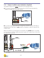
11.2
Cases in which a psu module is required
This power supply unit is always required in the following cases:
a) the network management is achieved with an RS-232 serial standard by
means of a DigiCrown 232/USB module;
Soluzione con RS232
232
box box 232 bus
bus bus bus psc
b) the power supply generated by the DigiCrown PCI/ISA modules (RS-485) is
insufficient for a long cable: a psu module is installed in order to cope with the
voltage drops.
When the network is connected to the computer via a pci/isa card, it is usually
not necessary to install an additional power supply unit, unless there is the situation described in point B.
232
box psu
bus bus
bus psc
}
box box
isa
L ≥ 10 mt.
31 UNITS
- 82 -
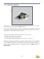
11.3
End line connector
The end line connector is inserted as a closing element in each NET, and physically applied to the last DigiCrown bus module.
The function of this device is to indicate, by means of its integrated LED, whether
the network is supplied with power at a voltage sufficient to ensure the correct
operation of all the modules that are present.
There are three types of display in the network end connector:
• LED OFF Î voltage in bus insufficient
• LED ON (green light) Î voltage OK
• LED FLASHING (red/green light) Î ommunication in bus active
Should the voltage be insufficient to supply the network (point 1), it is necessary
to install an auxiliary psu unit. Another solution may be for the user to remove
some modules in sequence until the LED of the network end connector lights up,
and to create an additional network (managed by means of a 232 interface or
pci/isa card)..
- 83 -
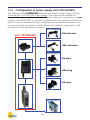
11.4
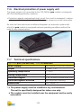
Configuration of power supply unit (100-240VAC)
The ordering code 767W000000 identifies the network power supply unit that
functions with a 100-240 VAC input voltage. This code includes several elements, but is not ready for use: it is necessary to order, as an accessory, the psc
module (code 6872030011), and also the element for the connection to the local
network (network cables and plugs complying with the standard adopted in the
country where the equipment is used). Below, the available configurations. with
the relevant ordering codes, are shown.
Cod.: 4147000016
• EU extension
Cod.: 767W000000
Cod.: 4147000019
Cod.: 4147000017
• USA extension
Cod.: 4147000013
• EU plug
Cod.: 4147000014
• USA plug
Cod.: 4147000015
• UK plug
Cod.: 4147000011
- 84 -
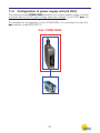
11.5
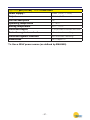
Configuration of power supply unit (24 VDC)
The ordering code 767W010000 identifies the network power supply unit that
functions with a 24 VDC input voltage (machine voltage). The 24 VDC psu module is supplied with a 5m long electrical connection cable.
To complete the configuration of the 767W010000, it is necessary to order the
psc module (code 6872030011).
Cod.: 767W010000
Cod.: 4147000011
- 85 -
11.6
Electrical protection of power supply unit
The power supply unit connected to the 100-240Vac psu module is equipped
with the following protection systems:
• Protection against overload and short circuit: the circuit is equipped, in series,
with a renewable fuse that is blown if there is an excessive current absorption.
As soon as these abnormal conditions disappear, an automatic system with
which the psu module is equipped restores operating conditions without the
need for any manual action.
11.7
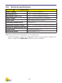
Technical specifications
DigiCrown psu (100-240 Vac) - code 767W000000
Power supply*
100-240Vac / 47-63 Hz / 400mA
Output
7,5Vdc / 1,7A
Operating temperature
0 ÷ 40°C
Storing temperature
-20 ÷ +70°C
Protection degree
IP 43 (on side of interface with bus)
Protection against overload
with automatic resetting
Dimensions
see Chapter 15
* Î The power supply must be installed in dry environments.
The unit is specifically designed for indoor use only.
Î The
sockets must be installed near the equipment and be easily
accessible.
- 86 -
DigiCrown psu (24 Vdc) - code 767W010000
Power supply**
24Vdc (-20% / + 20%)
Output
7,5 Vdc / 1.8A
Current absorption
1A
Operating temperature
0 ÷ 40°C
Storing temperature
-20 ÷ +70°C
Protection degree
IP 43 (on side of interface with bus)
Protection against overload
with automatic resetting
Protection against inversion
with automatic resetting
Dimensions
see Chapter 15
**Î Use a SELV power source (as defined by EN60950)
- 87 -
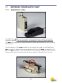
12
SYNCHRONISMS
Using this feature, the acquisition will be for all measuring points at the same time,
allowing a more correct implementation for dynamic measurements. The control
for the acquisition of the measure can be given in three different ways:
by USB
If the USB module is used to control the timing for the acquisition, a time synchronism will occur. The measure will be performed at regular time intervals according
to the scheduled period.
by I/O
If the I / O module is used to control the data acquisition, this will occur after an
event related to an I / O, such as pressing a button.
by encoder
If the encoder module is programmed to control the acquisition of the measure,
the measure will be carried out according to the position of the encoder itself.
For example, in case of a rotating piece, this type of synchronization ensures that
the measure is carried out always in the same point, freeing it from the time and
the rotation speed of the workpiece.
All acquired data are stored in the memory inside the USB module, so that it can
be accessed through the SDK or the protocol commands.
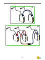
Synchronization is also planned to be used with more networks. It is possible in
fact to make multiple networks synchronized and therefore the measure carried
out at the same time. In the configuration in which two networks are to be synchronized the cable to use has two male circular connectors (code: 6735933007) and
it should be connected as shown in Figure A. For configurations with 3 or more
networks (max. 16) n-1 have to be used cables with three connectors (2 males
and one female, code: 6735931013) and a cable with two male connector as illustrated in figure B, where n is the number of networks.
Note:
The 2 Channel box module and Analog Input module support High
Speed Sync mode, providing enhanced network performance.
- 88 -
A
PC
USB
USB
PC
PC
USB
USB
PC
USB
PC
B
n-1
- 89 -
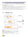
13
LED FOR DISPLAY OF UNIT OPERATING STATUS
The type of lighting of the red LED on the box module indicates the operating
status of the unit.
There are the following flashing modes:
• “ON ERROR” (the LED is activated only when an error is generated – par. 13.1)
• “AUTOMATIC” (this mode includes both the ON ERROR warning and brief
flashes to indicate the sessions pending in the network – par. 13.2).
• “DETECTION” (during the initial pencil probe mapping stage, the activation of a
sensor connected to a box module causes the relevant LED to light up).
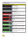
13.1 “ON ERROR” mode
Note:
(1) HW ERROR Î general hardware and bootstrap errors
(2) APPLICATION ERROR Î specific errors of the box
E.g.: transducer-disconnected alarm, etc.
(3) COM ERROR Î error in serial RS-485 communication
- 90 -
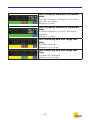
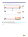
13.2 “AUTOMATIC” mode
Note:
(4) OK Î the network is in working order
(5) APPLICATION SESSION PENDING Î pending measurement status of the
box module - E.g.: dynamic/vectorized measurement status, etc.
(6) NETWORK SESSION PENDING Î identification session of the various network units
- 91 -
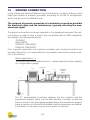
14
GROUND CONNECTION
In this chapter are reported different technical solutions in order to make sure the
DigiCrown system is properly grounded, according to the NET’s configuration
and to the lay-out of the different units.
The purpose of ground connection is to minimize as much as possible
the electrical noise and the interference, typically affecting the measurement signal.
The ground connections schemes reported in this paragraph represent the optimal solution in order to have a system fully compatible with the EMC standards,
according to the following directives:
73/23/EEC
2004/108/CE
EN55022: 1998 (EMC)
EN55024: 1998 (EMC)
If for a specific application the customer considers such technical solutions not
required, Marposs is not responsible for any possible inaccurate working condition of the devices.
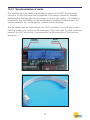
Bench application n. 1
The whole DigiCrown system (control + measurement) has been placed
on a single bench gauge.
PC
serial link
D
box
transducer
support
frame
A
p.e.
The “D” equipotential connection between the box modules and the
transducers support frame, can be done whether a metallic conductive
frame is used. In the glass gauging applications the transducers support
frame is usually not a conductive material and the transducers are typically insulated, in this case no ground connection is required.
- 92 -
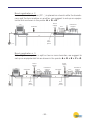
Bench application n. 2
In case the control system (PC…) is placed on a bench while the transducers and the box modules on another, we suggest to set-up an equipotential link as shown in the points: A + D + E.
Power
supply
unit
PC
serial link
box
D
transducer
support
frame
A
E
A.C.
Main
power
p.e.
Bench application n. 3
If the DigiCrown system is split on two or more benches, we suggest to
set-up an equipotential link as shown in the points: A + D + E + F + G.
PC
Power
supply
unit
serial link
box
F
transducer
support
frame
Power
supply
unit
serial link
G
A
E
D
p.e.
A.C.
Main
power
A.C.
Main
power
- 93 -
box
transducer
support
frame
Automatic machine application
For such applications it is strongly suggested to provide the box units and
the transducers support frame with an equipotential link: in the automatic
machine applications the eddy-currents normally flow in the transducer’s
shield.
Electrical cabinet
PC
Measuring machine
box
serial link
p.e.
Ground bar
Ground bar
Equipotential
link
- 94 -
Metallic connection
between the modules
and the transducers
15
INSTALLATION DIAGRAMS
15.1 Box module
15.2 Bus module
Locking
device
- 95 -
Hooking of box module to bus connector.
Dimensions of fastening to stand
79 (by means of fastening tongues)
54 (by means of connector)
25
25
Connectors in cascade
4.2
- 96 -
57
9
40
62
15.3 Dimensional drawings Digi PBB unit
5
112.3
61.5
66.5
30.15
52
30.15
- 97 -
16
DECLARATION OF CONFORMITY
MARPOSS S.p.A. hereby declares that the devices referred to in this manual conform to
safety requirements and EMC electromagnetic compatibility requirements, in accordance with the following directives:
73/23/EEC
2004/108/EC
of 19-02-1973 (LOW VOLTAGE directive)
of 20-01-2005 (EMC directive)
The apparatuses were designed, assembled and tested in conformity with the
following European standards:
EN60950: 2000 (Safety)
EN61326 - 1: 1997 (EMC)
EN61326/A1: 1998 (EMC)
- 98 -
17
ORDER CODES
The tables below provide a summary of the order codes for all components in the
DigiCrown Probing Line.
INTERFACES
DESCRIPTION
ORDER CODE
C
DIGI CROWN BOX
767X000100
C
DIGI CROWN BOX + RAM
767X000210
C
DIGI CROWN BOX 2 TRANSDUCERS
767X200400
D
DIGI CROWN 232 FULL SPEED
767Y000100
D
DIGI CROWN USB HIGH SPEED SYNC INT
767Y010500
D
DIGI CROWN USB HIGH SPEED SYNC INT + EXT
767Y010505
D
DIGI CROWN USB FULL SPEED
767Y010100
H
DIGI CROWN PSU (110-240VAC/7,5VDC)
767W000000
H
DIGI CROWN PSU (24VDC/7,5VDC)
767W010000
O DIGI CROWN AI UNIVERSAL HIGH SPEED
767A000400
P
DIGI CROWN EI HS D-SUB9
767E010500
E
DIGI CROWN I/O 24V SINK-HS SYNC
767I000500
E
DIGI CROWN I/O 24V SOURCE-HS SYNC
767I010500
E
DIGI CROWN I/O ONLY INPUT-HS SYNC
767I020500
- 99 -
K
DIGI CROWN PCI
6355321100
K
DIGI CROWN ISA
6355322100
EXTENSIONS
DESCRIPTION
ORDER CODE
M EXTENSION WITH POWER SUPPLY 2M
6738057027
M EXTENSION WITH POWER SUPPLY 3,5M
6738057029
M EXTENSION WITH POWER SUPPLY 6M
6738057031
M EXTENSION WITH POWER SUPPLY 10M
6738057033
M EXTENSION WITH POWER SUPPLY 15M
6738057035
ACCESSORIES
DESCRIPTION
ORDER CODE
G
DIGI CROWN PBB
6139013200
J
END LINE CONNECTOR
6355200000
F
DIGI CROWN BUS
6872030010
I
DIGI CROWN PSC
6872030011
N
EU PLUG
4147000013
N
UK PLUG
4147000015
N
USA PLUG
4147000014
N
EU CABLE
4147000016
N
USA CABLE
4147000017
SW PAKAGES
DESCRIPTION
ORDER CODE
L
QUICK SPC
CM2Z32MA00
L
MDHQSPC V.3.2
CM2E32MA12
L
EASY ACQUISITION
CM2F23MA01
L
EASY ACQUISITION SPC
CM2F23MA01
L
SDK DIGICROWN
XXXXXXXXXX
- 100 -
NOTES
_____________________________________________________________________
_____________________________________________________________________
_____________________________________________________________________
_____________________________________________________________________
_____________________________________________________________________
_____________________________________________________________________
_____________________________________________________________________
_____________________________________________________________________
_____________________________________________________________________
_____________________________________________________________________
_____________________________________________________________________
_____________________________________________________________________
_____________________________________________________________________
_____________________________________________________________________
_____________________________________________________________________
_____________________________________________________________________
_____________________________________________________________________
_____________________________________________________________________
- 101 -
2002/95/CE
2002/96/CE
INFORMATION FOR USERS
concerning the terms of the National Legislation enforcing the Directives 2002/95/EC,
2002/96/EC and 2003/108/EN on the restriction of the use of certain hazardous substances
in electrical and electronic equipment, and the disposal of waste materials
The wheel bin symbol with a cross through it on the equipment or its packaging indicates that the product
must be disposed of separately from other waste materials at the end of its working life.
If the user wishes to dispose of this equipment, he/she must do so in accordance with the applicable National regulations governing the separation of the unit into its waste materials at the end of its working life.
Separating waste materials correctly before submitting the equipment for recycling, treatment and environmentally compatible disposal can help to prevent potentially negative effects on health and the environment, as well as making it easier to reuse and/or recycle its constituent materials.
Failure to dispose of this product in accordance with these indications is punishable in accordance with
the applicable laws.
A complete and updated list of the addresses is available in the Marposs website: www.marposs.com
D4340050G7 - Edition 02/2012 - Specifications subject to changes.
© Copyright 2012 MARPOSS S.p.A. (Italy) - All rights reserved.
MARPOSS, and other names/marks relevant to Marposs products mentioned or shown in this document, are registered trademarks
or Marposs trademarks in the United States and in other countries. Any rights of third parties to trademarks or registered trademarks
mentioned in this document are acknowledged to the respective holders.
Marposs has an integrated Company Management system for quality, environment and safety, certified by ISO
9001, ISO 14001, OHSAS 18001 and QS9000 T&E certifications. Marposs has been awarded the EAQF 94 Qualification and the Q1-Award.