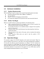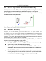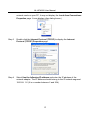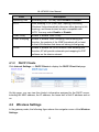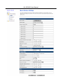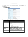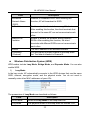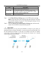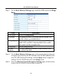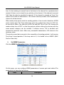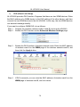
1
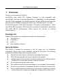
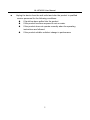
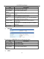
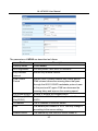
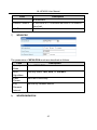
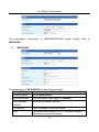
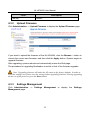
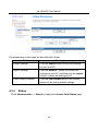
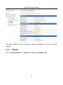
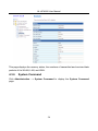
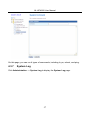
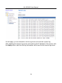
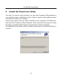
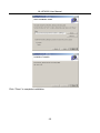
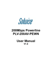
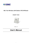
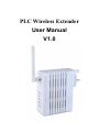
PLC Wireless Extender User Manual V1.0 NL-HPW200 User Manual Contents About User Manual................................................................................................... 1 Organization ............................................................................................................. 1 1 Overview ......................................................................................................... 4 2 Hardware Description ...................................................................................... 6 2.1 LED Status .......................................................................................... 6 2.2 Interface Description ........................................................................... 7 2.2.1 The Ethernet Interface .............................................................. 7 2.2.2 The Adapter's Buttons ............................................................... 8 2.3 Hardware Installation ........................................................................... 9 2.3.1 System Requirements............................................................... 9 2.3.2 Before You Begin ...................................................................... 9 2.4 Operation Range ................................................................................. 9 2.5 How to Improve the Transmission Capacity ....................................... 10 2.6 Wireless Roaming ............................................................................. 10 3 Wireless Network Configuration ..................................................................... 11 3.1 TCP/IP Settings ................................................................................. 11 3.2 Log In to the Web Page ..................................................................... 14 4 Web Configuration ......................................................................................... 15 4.1 Internet Settings ................................................................................ 15 4.1.1 LAN ........................................................................................ 15 4.1.2 DHCP Clients.......................................................................... 18 4.2 Wireless Settings .............................................................................. 18 4.2.1 Basic ...................................................................................... 19 4.2.2 Advanced ............................................................................... 30 4.2.3 Security .................................................................................. 37 4.2.4 WPS ....................................................................................... 46 4.2.5 Station List .............................................................................. 50 4.3 Administration ................................................................................... 50 4.3.1 Management........................................................................... 51 4.3.2 Upload Firmware .................................................................... 53 4.3.3 Settings Management ............................................................. 53 i NL-HPW200 User Manual 5 6 7 8 9 4.3.4 Status ..................................................................................... 54 4.3.5 Statistic ................................................................................... 55 4.3.6 System Command .................................................................. 56 4.3.7 System Log............................................................................. 57 Install the PowerLine Utility ............................................................................ 59 How to Use The Utility Software .................................................................... 61 6.1 Main Tab ........................................................................................... 61 6.2 Privacy Tab ....................................................................................... 63 6.3 Diagnostics Tab ................................................................................ 64 6.4 About Tab ......................................................................................... 66 How to use the NMK Pushbutton ................................................................... 67 7.1 Forming a HomePlug AV logical network ........................................... 67 7.2 Joining a Network .............................................................................. 68 7.3 Leaving a Network............................................................................. 68 About PowerLine QoS ................................................................................... 70 Parameter and Specification .......................................................................... 71 ii NL-HPW200 User Manual About User Manual This user manual mainly describes how to install and configure the NL-HPW200 wireless extender. Organization This user manual is organized as follows: Chapter Description Chapter 1 : Overview Provides a general overview of the NL-HPW200 wireless router, and the package list. Chapter 2 : Hardware Description Mainly describes the front panel and the rear panel of the NL-HPW200 and the procedure for hardware installation. Chapter 3 : Wireless Network Configuration Describes how to configure network settings of your PC, then connect to the NL-HPW200. Chapter 4 : Web Configuration Mainly describes how to navigate through the Web pages and how to configure the parameters. Chapter 5 : Install the PowerLine Utility Introduce installation of the PowerLine Utility Chapter 6 : How to use the Utility Software Describes how to view the PowerLine parameter, modify NMK, device name Chapter7 : How to use the NMK pushbutton Introduce how to form, join and leave a HomePlug AV local network Chapter8 : About PowerLine QoS Introduce how to setup the QoS parameter in PowerLine function Chapter9 : Parameter and Specification Introduce the product system specification 1 NL-HPW200 User Manual Features PowerLine Feature Power supply range of 100 ~ 240VAC 50/60Hz Comply with HomePlug AV, and Co-existence with HomePlug 1.0 Nodes PowerLine phy rate up to 200 Mbps Support QAM 1024/256/64/16/8, QPSK, BPSK, and ROBO modulation schemes 128-bit AES Link Encryption with key management for secure power line communications Windowed OFDM with noise mitigation based on patented line synchronization techniques improves data integrity in noisy conditions Dynamic channel adaptation and channel estimation maximizes throughput in harsh channel conditions Priority-based CSMA/CA channel access schemes maximize efficiency and throughput Integrated Quality of Service (QoS) Enhancements: contention-free access, four-level priority based contention access, and multi segment bursting ToS and CoS Packet Classifiers Supports IGMP managed multicast sessions Wireless Feature Support IEEE802.11b, IEEE802.11g, IEEE802.11n, IEEE802.3, IEEE802.3u, IEEE802.11i, and IEEE802.11e Support 1T1R mode and transmission data rate is up to 150 Mbps Support WEP and WPA for data transmission security Support DHCP Server and Client Support firmware version upgrade via Web page Support restoring factory default settings Support wireless security authentication modes, including OPEN, SHARED, WEPAUTO, WPA, WPA-PSK, WPA2, WPA2-PSK, WPA-PSK/WPA2-PSK, WPA1WPA2, and 802.1X. 2 NL-HPW200 User Manual Support system status display Support cross-over cable detection and also support auto modification and polarity modification Support system log 3 NL-HPW200 User Manual 1 Overview Thank you for choosing NL-HPW200. NL-HPW200 (also called PLC Wireless Extender) is fully compatible with HomePlugAV, and can co-exist with HomePlug 1.0 . Meanwhile, it is also compatible with 802.11b/g/n standards. NL-HPW200 supports CCK and OFDM and its PowerLine phy rate is up to 200Mbps, wireless phy rate is up to 150 Mbps under 11n mode. NL-HPW200 provides 128-bit AES encryption in PowerLine communication, 64-bit and 128-bit WEP encryption, WPA encryption in wireless communication, associating with IEEE 802.1X authentication, which insures the security of wireless communication. Package list Please check whether your package list includes the following items: NL-HPW200 x 1 CD-ROM x 1 RJ45 x 1 Quid installation Guide x 1 Security Notes This device is intended for connection to the AC power line. For installation instructions, please refer to the installation section of this guide. The following precautions should be taken when using this product. Read all instructions before installing and operating this product. Follow all warnings and instructions marked on the product. Unplug the device from the wall outlet before cleaning. Use a damp cloth for cleaning. Do not use liquid cleaners or aerosol cleaners. Do not operate this product near water. This product should never be placed near or over a radiator or heat register. Do not use an extension cord between the device and the AC power source. Only a qualified technician should service this product. Opening or removing covers may result in exposure to dangerous voltage points or other risks. 4 NL-HPW200 User Manual Unplug the device from the wall outlet and refer the product to qualified service personnel for the following conditions: If liquid has been spilled into the product If the product has been exposed to rain or water If the product does not operate normally when the operating instructions are followed If the product exhibits a distinct change in performance 5 NL-HPW200 User Manual 2 2.1 Hardware Description LED Status There are 5 LED indicators on the front panel of NL-HPW200. By observing their status, you can judge whether the device runs normally. 6 NL-HPW200 User Manual The following table describes the status of LED indicators on the front panel. LED Indicator Color Status Description PWR Red On Power is on. Green On The device runs normally. - Off Power is off or the device is down. Green On Radio switch is turned on. Green Blink Data is being transmitted. - Off Radio switch is shut off. Green On Connection succeeds under Wi-Fi Protected Setup. Green Blink Negotiation is in progress under Wi-Fi Protected Setup. - Off Wi-Fi Protected Setup is disabled. Green On/Blink When PLC rate﹥100Mbps, see note 1 Orange On/Blink When PLC rate in 80-100Mbps, see note 1 Red On/Blink When PLC rate﹤100Mbps, see note 1 Green On Connection succeeds. Green Blink Data is being transmitted. - Off No LAN connection. WLAN WPS PLC LAN Note: The PLC LED indicator turns “ON” when powerline link is detected. If the device is serving as a STATION, the LED indicator will blink to indicate transmit or receive powerline activity. If the device is serving as a CCO, the LED indicator will light steadily ON, even in the presence of powerline activity 2.2 Interface Description 2.2.1 The Ethernet Interface Ethernet : The Ethernet port connects to an Ethernet network cable. The other end of the cable will connect to 7 NL-HPW200 User Manual your computer or other Ethernet-enabled network device. 2.2.2 The Adapter's Buttons RST: NMK: WPS: The RST button can restore the factory defaults. The button is used to synchronous the private network name. This button is used for enabling WPS PBC mode. If WPS is enabled, press this button, and then the extender starts to accept the negotiation of PBC mode Note: Do not press the Reset button unless you want to clear the current settings. The Reset button is in a small circular hole on the rear panel. If you want to restore the default settings, please press the Reset button gently for 3 seconds with a fine needle inserted into the hole and then release the button. The system reboots and returns to the factory defaults. 8 NL-HPW200 User Manual 2.3 2.3.1 Hardware Installation System Requirements Before installing the device, please make sure that the following items are ready. At least one Ethernet RJ45 cable (10Base-T/100Base-T) 2.3.2 One NL-HPW200 One PLC device for PowerLine communication A PC has been installed PCP/IP protocol and it can access the Internet. Before You Begin Before you install the device, please pay attention to the following items: When connecting the device to a computer, a hub, a router or a switch, the Ethernet cable should be less than 100 meters. 2.4 Do not place this device on an unstable surface or support. Do not put this device on the ground. Keep the device clean. Avoid the device from direct sunshine. Avoid any metal in the device. Place the device in the center of the area, and try to optimize the wireless coverage. Install Powerline Utility when you want to see the quality of PLC communication Operation Range The operation range of NL-HPW200 depends on the actual environment. When the device is placed in the house or in the office, the overall arrangements are different. So the path and effect for signal transmission are different. For PLC network the typical coverage Up to 5000 square foot, but the actual Coverage will vary with the power grid and the number of PLC terminal device. For wireless, the outdoor straight transmission distance for some devices in the open air is up to 300 meters, and the indoor straight transmission distance is up to 100 meters. 9 NL-HPW200 User Manual 2.5 How to Improve the Transmission Capacity It is important to use the PLC product complying with the following "correct rules", because it can significantly improve the transmission capacity of the network. For the PLC device no female socket, it is recommended to plug the device directly into a wall socket, not to power stripe. Note:Please don’t plug the device in horizontal. 2.6 Wireless Roaming Suppose that one NL-HPW200 and several APs run in the same network. The NL-HPW200 or AP acts as one BSS, and has its coverage range. One wireless client terminal (e.g. notebook PC or PDA), can realize roaming from one AP to another AP correctly. In that case, the wireless client terminal can communicate with the other devices within the NL-HPW200 and APs’ coverage. In order to realize the wireless client roaming among different APs, you need to set the NL-HPW200 and APs properly. Do as follows: Set the same SSID for NL-HPW200 and all APs. The SSIDs of all the computers and PDAs should be consistent with the APs. All the BSSs must use the same wireless channel. If the encryption function is enabled, all the NL-HPW200 and APs should configure the same encryption mode and the encryption key for establishing connection. The NL-HPW200 and APs must keep the wireless signal covering the whole operation environment and the wireless signal should be continuous. Please put the APs to the appropriate places for a better network coverage. 10 NL-HPW200 User Manual 3 Wireless Network Configuration Web management tool allows you to configure wireless function of NL-HPW200, but not PLC function, the PLC function should install the PowerLine Utility to configure and will introduce in back chapter. The web management only for wireless function, the recommended browser is IE 5.0 or above. The following sections describe how to set the Internet connection, local Ethernet connection, and wireless connection, and how to access the Web page of the NL-HPW200. 3.1 TCP/IP Settings By default, the IP address of LAN interface of the NL-HPW200 is 192.168.1.1.The subnet mask is 255.255.255.0. The DHCP Server is enabled. It is recommended you set the network adapter to be Obtain an IP address automatically. Your PC acquires IP address, subnet mask, gateway, and DNS address automatically via the extender. If you know the setting of the current LAN interface, you can manually set the TCP/IP properties of the network adapter, so that your PC can communicate with the extender. You may manually set the network adapter by following the steps below: Step 1 Right click the icon of My Network Places (e.g., Windows XP) and select Properties in the menu. The Network Connections page appears. Step 2 Right click the network adapter icon and select Properties in the menu. The Local Area Connections Properties appears. (Note: If there are several 11 NL-HPW200 User Manual network cards on your PC, it may not display the Local Area Connections Properties page. It may display other dialog boxes.) Step 3 Double click the Internet Protocol (TCP/IP) to display the Internet Protocol (TCP/IP) Properties page. Step 4 Select Use the following IP address and enter the IP address of the network adapter. The IP address should belong to the IP network segment 192.168. 1.X (X is a number between 2 and 254). 12 NL-HPW200 User Manual Step 5 Step 6 Set the subnet mask and then click the OK button to finish manual setting. After finishing setting, you may ping the default IP address of the the extender, to check whether the current connection between PC and the extender is normal. Click RUN… in the lower left corner on the desktop, and then enter ping 192.168.1.1 in the dialog box. See the following figure: Note: 192.168.1.1 is the default IP address of the LAN interface. If this IP address is changed and you need to ping the IP address of the extender, you should enter the current IP address in the dialog box above. Step 7 If PC can ping through the default IP address of the extender and the following page appears, it indicates that the connection between PC and AP is normal. 13 NL-HPW200 User Manual 3.2 Log In to the Web Page Open the browser, and enter the http://192.168.1.1/ in the IE address bar. Enter the user name (admin, by default) and the password ( admin. by default) on the login page. After clicking the OK button on the login page, you can log in to the Web page of the NL-HPW200. 14 NL-HPW200 User Manual 4 Web Configuration 4.1 Internet Settings The following figure shows the navigation menu of the Internet Settings: The sub-menus of the Internet Settings include LAN, and DHCP clients. 4.1.1 LAN Click Internet Settings --> LAN to display Local Area Network (LAN) Settings page. 15 NL-HPW200 User Manual This page is used to configure the LAN parameters. This page allows you to configure LAN interface properties, DHCP server properties, and other parameters related to LAN. The parameters on this page are described as follows: 16 NL-HPW200 User Manual Field Description IP Address The IP address of LAN interface. The default IP address is 192.168.1.1. Subnet Mask The subnet mask of the IP address of the LAN interface. The default subnet mask is 255.255.255.0. LAN 2 Enable or disable the second IP address of the LAN interface. The default setting is Disable. LAN 2 IP Address The second IP address of the LAN interface. This IP address should not collide with the IP address of the interior network. LAN 2 Subnet Mask The subnet mask of the second IP address of the LAN interface. MAC Address Display the current MAC address that LAN interface uses. DHCP Type Enable or disable DHCP service. The default setting is Server, it indicates DHCP service is enabled. After enabling DHCP service, you can configure the following parameters of the DHCP server: Start IP Address: The start IP address of the DHCP address pool. End IP Address: The end IP address of the DHCP address pool. Subnet Mask: The subnet mask that DHCP server assigns. Primary DNS Server: The primary DNS server that DHCP server assigns. Secondary DNS Server: The secondary DNS server that DHCP server assigns. Default Gateway: The gateway that DHCP server assigns. Lease Time: The lease time of the IP address. Statically Assigned: For binding MAC and IP. 802.1d It can provide redundant link and prevent network from 17 NL-HPW200 User Manual Field Description Spanning Tree generating loop. You may select Enable or Disable. LLTD After enabling LLTD (Link Layer Topology Discovery), Windows Vista automatically discovers other devices’s link topology, and these devices are also compatible with LLTD. You may select Enable or Disable. IGMP Proxy Enable or disable IGMP Proxy. IGMP Snooping Enable or disable IGMP Snooping. After enabling this function, the packets of the IGMP broadcast will not sent to the LAN interface that does not belong to that group. UPNP Enable or disable the UPnP function. After enabling this function, AP will provide automatic port-mapping for P2P software on the interior network. 4.1.2 DHCP Clients Click Internet Settings --> DHCP Clients to display the DHCP Client List page. On this page, you can view the clients’s information assigned by the DHCP server, including the MAC address, the IP address, the lease time of the IP address and so on. 4.2 Wireless Settings In the gateway mode, the following figure shows the navigation menu of the Wireless Settings: 18 NL-HPW200 User Manual In the gateway mode, the sub-menus of the Wireless Settings include Basic, Advanced, Security, WPS, and Station List. 4.2.1 Basic Click Wireless Settings --> Basic to display the Basic Wireless Settings page. 19 NL-HPW200 User Manual 20 NL-HPW200 User Manual On this page, you may set the parameters of wireless network, WDS, and HT Physical mode. Wireless Network The parameters of Wireless Network are described as follows: Field Description Radio On/Off Enable or disable wireless LAN interface. Network Mode You may select a proper network mode in the drop down list. 11b/g mixed mode 11b only 11g only 11b/g/n mixed mode (default) Network Name (SSID) The maximum character number for SSID is 32 characters. The legal characters include letter, number underline or the combination of these characters. Multiple SSID1~7 Accessional network SSID. Each SSID can use wireless security setting independently. 21 NL-HPW200 User Manual Field Description Broadcast Network Name (SSID) Whether to broadcast SSID. After enabling this function, AP will broadcast its SSID. AP Isolation Enable or disable the isolation among AP clients. After enabling this function, the client terminals that connect to the same AP can not communicate each other. MBSSID AP Isolation Enable or disable the isolation among different SSIDs. After enabling this function, the client terminals with different SSIDs can not communicate each other. BSSID The MAC address of the wireless interface. Frequency (Channel) You may select a proper channel in the drop down list. The default channel is Channel 6. Wireless Distribution System (WDS) WDS modes include Lazy Mode, Bridge Mode, and Repeater Mode. You can also enable WDS. 1) Lazy Mode In the lazy mode, AP automatically connects to the WDS devices that use the same SSID, channel, encryption mode, and the physical mode. You do not need to manually enter other MAC addresses of peer APs. The parameters of Lazy Mode are described as follows: Field Description WDS Mode Select the Lazy Mode in the drop down list. Phy Mode The physical modes in the drop down list include CCK, 22 NL-HPW200 User Manual Field Description OFDM, HTMIX, and GREENFIELD. Encryp Type The encryption types you can select include NONE, WEP, TKIP, and AES. If selecting WEP, TKIP, or AES, you need to set the encryption key. Encryp Key Set the encryption key. Step 1 Step 2 On the Basic Wireless Settings page, set the WDS mode to be Lazy Mode, set the same phy mode and encryp type with the peer AP, and then enter the MAC address of the peer AP. After finishing the settings, click the Apply button to apply the settings. Enter the Wireless Security/Encryption Settings page, set the security mode of the NL-HPW200 to accord with the peer AP. 2) Bridge Mode In the bridge mode, you can use the NL-HPW200 to connect to your router, for extending wireless coverage. Meanwhile, it can also decrease the working load of the AP that accesses the Internet. In that case, the wireless card does not directly communicate with the wireless device that accesses the Internet, but it directly communicates with the NL-HPW200. 23 NL-HPW200 User Manual Step 1 On the Basic Wireless Settings page, select the WDS mode to be Bridge Mode. Field Description WDS Mode Select the Bridge Mode. Phy Mode The physical modes in the drop down list include CCK, OFDM, HTMIX, and GREENFIELD. Encryp Type The encryption types you can select include NONE, WEP, TKIP, and AES. If selecting WEP, TKIP, or AES, you need to set the encryption key. Encryp Key Set the encryption key. AP MAC Address The MAC address of another AP that connects to the NL-HPW200 by WDS. Step 2 Step 3 On the Basic Wireless Settings page, set the same physical mode and encryption type with the peer AP, and then enter the MAC address of the peer AP. After finishing the settings, click the Apply button to apply the settings. The NL-HPW200 will work in the Bridge mode. Enter the Wireless Security/Encryption Settings page, set the security mode of the NL-HPW200 to accord with the peer AP. 24 NL-HPW200 User Manual 3) Repeater Mode In the Repeater mode, you can use the NL-HPW200 to connect to the primary router, for extending the wireless coverage. Step 1 Click Wireless Settings --> Basic to display Basic Wireless Settings page. 25 NL-HPW200 User Manual Step 2 Step 3 Set the Frequency(channel) according with the peer AP (An AP that wants to connect to the NL-HPW200 by WDS). On the Basic Wireless Settings page, set the WDS mode to be Repeater Mode, set the same physical mode and encryption type with the peer AP, and then enter the MAC address of the peer AP. After finishing the settings, click the Apply button to apply the settings. The NL-HPW200 will work in the Repeater Mode. 26 NL-HPW200 User Manual Step 4 Click Wireless Settings --> Security to display the Wireless Security/Encryption Settings page. Step 5 On this page, set the security mode of the NL-HPW200 to accord with the peer AP. Note: In the WDS mode, don’t set any mixed modes, for example, WPA-PSK/WPA2-PSK. Do not set all the WDS APs to be Lazy mode, please ensure that at least one WDS AP acts as Root Bridge, and enter the MAC addresses in the WDS table on the Basic Wireless Settings page HT Physical Mode 27 NL-HPW200 User Manual The parameters of HT Physical Mode are described as follows: Field Description Operation Mode You may select Mixed Mode or Green Field. The default operation mode is Mixed Mode. Channel BandWidth You may select 20 or 20/40. The default channel bandwidth is 20/40. Guard Interval You may select Long or Auto. The default guard interval is Auto. MCS You may select the MCS value from 0 to 32. The default MCS is Auto. Reverse Direction Grant (RDG) You may select Disable or Enable. The default RDG setting is Enable. Extension Channel When the channel bandwidth is set to be 20/40 MHz, the extension channel will provide a channel that is adjacent to the primary channel but not overlaps. The wireless network will acquire diploid bandwidth by this extension channel, that is, 20MHz bandwidth. Aggregation MSDU (A-MSDU) Note: IEEE 802.11n can bind two adjacent 20 MHz bandwidths together to form a 40MHz bandwidth. Actually, the 40MHz bandwidth can act as two 20 MHz bandwidths. One is primary bandwidth, the other is secondary bandwidth. When data is being transmitted, it can act as 40MHz bandwidth, and it can also acts as 20 MHz bandwidth independently. In this way, the data rate is doubled. Enable or disable A-MSDU. MSDU is the aggregation of multiple MSDUs by using certain method and the multiple MSDUs forms a greater load. MSDU can be considered as Ethernet message. Usually, when AP or wireless client receives MSDUs from protocol stack, the MSDUs will be marked with the Ethernet message 28 NL-HPW200 User Manual Field Description header (also called A-MSDU Subframes). Before sending them out, the A-MSDU Subframes need to be transformed into the message format of 802.11 one by one. A-MSDU aggregates multiple A-MSDU Subframes and encapsulates them to be an 802.11 message. In this way, PLCP Preamble, PLCP Header, and 802.11 MAC overhead that are needed to send an 802.11 message decrease. At the same time, the acknowledge frames also decrease, and the efficiency for sending message is improved. Auto Block ACK Enable or disable Auto Block ACK. In order to insure the security of the data transmission, 802.11n protocol requires that if client receives a uincast frame, it should immediately send back an ACK frame. After the receiver of A-MPDU receives A-MPDU, it needs to process every MPDU. In that case, it sends out ACK frames to every MPDU. Block Acknowledgement is used to reduce the number of the ACK frames by using an ACK frame. Decline BA Request Enable or disable Decline BA Request. Other The parameters of HT TxStream and HT RxStream are described as follows: 29 NL-HPW200 User Manual Field Description HT TxStream The stream number that wireless antenna transmits. HT RxStream The stream number that wireless antenna receives. 4.2.2 Advanced Click Wireless Settings --> Advanced to display the Advanced Wireless Settings page. 30 NL-HPW200 User Manual On this page, you may configure advanced wireless parameters, such as beacon interval, data beacon rate, and Tx power. Note: The advanced wireless setting is only for advanced user. For the common user, do not change any setting on this page. Advanced Wireless 31 NL-HPW200 User Manual The parameters of Advanced Wireless are described as follows: Field You may select On, Off, or Auto. The default BG protection mode is Auto. Beacon Interval By default, wireless beacon signal sends data to station every other 100 ms. The range is 20~999. Data Beacon Rate (DTIM) The default DTIM is 1ms. The range is 1~255. Fragment Threshold The default fragment threshold is 2346. The range is 256~2346. RTS Threshold The default RTS threshold is 2347.The range is 1~2347. TX Power Set the Tx power. 100% indicates full power. Short Preamble Enable or disable short preamble. The default setting is Disable. Preamble defines the length of CRC correction block for wireless devices. Short preamble adopts 56-bit synchronization field. The network whose network stream is dense should use shorter preambles. Short Preamble is mainly applied to improvement the efficiency of real- time applications, such as streaming video, and Voice-Over-IP telephony. Enable or disable short slot. Short Slot Tx Burst Tx Burst can be used to improve the efficiency of data transmission. It can make system transmit more data during a period of time. Pkt_Aggregate Pkt_Aggregate can aggregate multiple data packets together for improving the transmission efficiency Select a proper country code in the drop down list. Country Code Description BG Protection Mode Wi-Fi Multimedia 32 NL-HPW200 User Manual The parameters of WMM are described as follows: Field Description WMM Capable Enable or disable WMM. After enabling WMM, AP can process different types of wireless data according to their priority levels. APSD Capable Enable or disable APSD. After enabling APSD, it can decrease the consumption of the power supply device. DLS Capable Enable or disable DLS WMM Parameters Click the WMM Configuration button to display WMM parameters configuration page. 1) WMM Access Categories At present, WMM defines traffic into 4 access categories. AC_VO: Voice (highest priority) AC_VI: Video (high priority) AC_BE: Best effort (medium priority) AC_BK: Background (low priority) 802.11 uses DCF (Distributed Coordination Function) scheme of the CSMA/CA (Carrier Sense Multiple Access / Collision Avoidance) protocol to reduce the chances of packets collision while one more devices access the wireless media at the same 33 NL-HPW200 User Manual time. A client wishing to transmit has to first listen to the channel for a predetermined amount of time so as to check for any activity on the channel. If the channel is sensed "idle" then the client is permitted to transmit. If the channel is sensed as "busy" the station has to defer its transmission. The random interval provides a fair transmission chance for all the devices. When each priority queue waits for sending packets, it has to wait a fixed time AIFSN and a random time CW. They define time values by multiple time slots. For 802.11b, its time slot is 20ms. The time slot of 802.11a and 802.11g is 9 ms. CW insures the random delay time of DCF, so that the packets collision among the devices with the same access category can be avoided. If collision occurs, CW is doubled until exceeds its maximum value. After every successful transmission, CW returns to the minimum value. The priority queue that succeeds in the competition of sending packets, it will acquire Txop time to send packets. If the txop value is 0, it is limited to be a MSDC (MAC Service Data Unit). 2) Set WMM Parameters Click the WMM Configuration button, the following page appears. On this page, you can configure WMM parameters of access point and station.The parameters are described as follows: Field Description 34 NL-HPW200 User Manual Field Description Aifsn Aifsn (Arbitrary Inter-Frame Space Number). This parameter influences the delay time of WMM access category. If you use voice or video service, you’d better set this parameter to be smaller in the fields of AC_VI and AC_VO. If it is E-mail or Web service, you should set a bigger value in the fields of AC_BE and AC_BK. Cwmin Cwmin (Mini. Contention Window) also influences the delay time of WMM access category. The difference between AC_VI and AC_VO should be smaller, but the difference between AC_BE and AC_BK should be bigger. Cwmax Cwmax (Max.Contention Window) Txop Txop (Opportunity to Transmit) may optimize the WMM access. Compared to the WMM access that needs a higher priority, such as AC_VI and AC_VO, this value should be bigger. ACM ACM (Admission Control Mandatory) parameter only reacts on AC_VI and AC_VO. If you set this value to be 0, it indicates that AP is in the charge of the access commands. If this value is 1, it means the client is in the charge of the access commands. Ackpolicy When WMM packets are transmitting, AP will receive an echo request. If you set this value is 0, it means AP does not send back an echo request, which will brings positive effect for WMM. If this value is 1, AP generates the response to the request. Note: NL-HPW200 provides standard WMM settings. If you want to modify the parameters above, please refer to the WMM settings of your WMM products. 35 NL-HPW200 User Manual 3) DLS (Direct Link Setup) NL-HPW200 provides DLS function. Suppose that there are two WMM devices. Enter the MAC address of a WMM device in the DLS setting of the other device, and then connect the two WMM devices to the NL-HPW200. In this way, the two WMM devices can transmit message directly. If you want to configure WMM DLS, do as follows: Step 1 Prepare two wireless network cards (A and B) and one NL-HPW200. Step 2 Enable the DLS function on the Advanced Wireless Settings page. Step 3 Enable the DLS function of wireless network cards. Enter the MAC address of wireless card A on the WMM page of the wireless network card B, and then click the Apply button. Step 4 If DLS succeeds, you can view the MAC address of wireless card A on the WMM page of wireless card B, and vice versa. 36 NL-HPW200 User Manual Multicast-to-Unicast Converter Enable or disable Multicast-to-Unicast. After enabling this function, the transmission quality of wireless multicast stream can be improved. 4.2.3 Security Click Wireless Settings --> Security to display the Wireless Security/Encryption Settings page. 37 NL-HPW200 User Manual This page allows you to configure wireless security modes and set the encryption keys, to prevent unauthorized access and monitoring. Select SSID SSID choice: select SSID that you want to configure. Security Mode This page provides 10 types of security modes, including OPEN, SHARED, WEPAUTO, WPA, WPA-PSK, WPA2, WPA2-PSK, WPAPSKWPA2PSK, WPA1WPA2, and 8021.X. 1) OPEN 38 NL-HPW200 User Manual The parameters of OPEN mode are described as follows: Field 2) Description Security Mode Select OPEN. Default Key Select a key as the default key. WEP Keys (WEP Key1/2/3/4) Set 64-bit or 128-bit key. The key format is Hex or ASCII. SHARED The parameters of SHARED mode are described as follows: Field Description Security Mode Select SHARED. Encrypt Type You may select WEP or None. Default Key Select a key as the default key. 39 NL-HPW200 User Manual Field WEP Keys (WEP Key1/2/3/4) 3) Description Set 64-bit or 128-bit key. The key format is Hex or ASCII. WEPAUTO The parameters’ description of WEPAUTO mode, please refer to OPEN mode. 4) WPA The parameters of WPA mode are described as follows: Field Security Mode Description Select WPA. 40 NL-HPW200 User Manual Field 5) Description WPA Algorithms You may select TKIP or AES. Key Renewal Interval Set the key renewal interval. WEP Keys (WEP Key1/2/3/4) Set 64-bit or 128-bit key. The key format is Hex or ASCII. IP Address The IP address of RADIUS server. Port The default port number is 1812. You may change it according to the server setting. Shared Secret The shared key that RADIUS server needs to authenticate. Session Timeout If this value is 0, it indicates that there is no session time limit. Idle Timeout Set the idle timeout. WPA-PSK The parameters of WPA-PSK mode are described as follows: Field 6) Description Security Mode Select WPA-PSK. WPA Algorithms Select TKIP or AES. Pass Phrase Set 8-bit to 64-bit key. Key Renewal Interval Set the key renewal interval. WPA2 41 NL-HPW200 User Manual The parameters of WPA2 are described as follows: Field Description Security Mode Select WPA2. WPA Algorithms You may select TKIP, AES, or TKIPAES Key Renewal Interval Set the key renewal interval. PMK Cache Period Set the PMK (Pairwise Master Key) cache period. PMK scheme allows the roaming users that pass through the 802.11X/EAP handshake protocol roam to the previous AP again. PMK can decrease the roaming delay and improve the roaming speed. Pre-Authentication Enable or disable pre-authentication. WEP Keys (WEP Key1/2/3/4) Set 64-bit or 128-bit key. The key format is Hex or ASCII. IP Address The IP address of RADIUS server. Port The default port number is 1812. You may change it according to the server setting. Shared Secret The shared key that RADIUS server needs to 42 NL-HPW200 User Manual Field Description authenticate. 7) Session Timeout If this value is 0, it indicates that there is no session time limit. Idle Timeout Set the idle timeout. WPA2-PSK The parameters of WPA2-PSK mode are described as follows: Field 8) Description Security Mode Select WPA2-PSK. WPA Algorithms You may select TKIP, AES, or TKIPAES. Pass Phrase Set 8-bit to 64-bit key. Key Renewal Interval Set the key renewal interval. WPAPSKWPA2PSK 43 NL-HPW200 User Manual The parameters’ description of WPAPSKWPA2PSK mode, please refer to WPA2-PSK. 9) WPA1WPA2 The parameters of WPA1WPA2 are described as follows: Field Description Security Mode Select WPA1WPA2. WPA Algorithms You may select TKIP, AES, or TKIPAES. Key Renewal Interval Set the key renewal interval. IP Address The IP address of RADIUS server. Port The default port number is 1812. You may change it according to the server setting. 44 NL-HPW200 User Manual Field Description Shared Secret The shared key that RADIUS server needs to authenticate. Session Timeout If this value is 0, it indicates that there is no session time limit. Idle Timeout Set the idle timeout. 10) 802.1X The parameters of 802.1X mode are described as follows: Field Description Security Mode Select 802.1X. IP Address The IP address of RADIUS server. Port The default port number is 1812. You may change it according to the server setting. Shared Secret The shared key that RADIUS server needs to authenticate. Session Timeout If this value is 0, it indicates that there is no session time limit. Idle Timeout Set the idle timeout. 45 NL-HPW200 User Manual Access Policy The parameters of Access Policy are described as follows: Field Policy Description Add a station Mac Disable: Stop the access control to the wireless devices in the MAC list. Allow: Allow the access control to the wireless devices in the MAC list. Reject: Reject the access control to the wireless devices in the MAC list. Enter the MAC address of wireless device that you want to allow or reject. After finishing the settings, click the Apply button to apply the settings. 4.2.4 WPS Click Wireless Settings --> WPS to display the Wi-Fi Protected Setup page. 46 NL-HPW200 User Manual On this page, you can modify the WPS settings. WPS can make your client automatically synchronize with the AP setting, and establish connection. WPS Config WPS: enable or disable WPS. After enabling WPS, you can configure the parameters related to WPS. 47 NL-HPW200 User Manual WPS Summary WPS summary displays the preset WPS information, such as WPS current status, WPS authentication mode, and WPS encryption type. Click the Reset OOB button to display the WPS default settings. WPS Progress WPS modes include PIN and PBC modes, At present, WPS supports three operation modes, including Enrollee mode, Registrar mode, and PBC mode. Enrollee and Registrar modes need to apply PIN code negotiation. 1) Step 1 Step 2 Step 3 2) Enrollee Mode Select Enrollee mode on the wireless client, the software of wireless client will generate a random PIN code, for example, 12345678. On the Wi-Fi Protected Setup page, enter the PIN code of wireless client, for example, 12345678. Click the Apply button on the Wi-Fi Protected Setup page to submit setting. Registrar Mode 48 NL-HPW200 User Manual Step 1 View the AP PIN on the Wi-Fi Protected Setup page, for example, 31668729. Step 2 Select Registrar mode on the wireless client and enter the PIN code of the NL-HPW200. See the following figure: 3) PBC Mode Step 1 On the Wi-Fi Protected Setup page, select the PBC mode, and then click the Apply button. You may also press the WPS button on the rear panel. Step 2 Enable the PBC function on the wireless client. In that case, NL-HPW200 and wireless client will automatically establish connection. WPS Status 49 NL-HPW200 User Manual The figure above displays WPS current status. 4.2.5 Station List Click Wireless Settings --> Station List to display the Station List page. On this page, you can view the wireless networks that connect to the NL-HPW200. If there is any wireless network connects to NL-HPW200, refresh this page and the connection information of the wireless network is displayed. 4.3 Administration The following figure shows the navigation menu of the Administration: The sub-menus of the Administration include Management, Upload Firmware, Settings Management, Status, Statistics, System Command and System Log. 50 NL-HPW200 User Manual 4.3.1 Management Click Administration --> Management to display the System Management page. This page provides administration settings, NTP settings, and DDNS settings. Language Settings Select Language: Only provide English. Administrator Settings 51 NL-HPW200 User Manual The parameters of Administrator Settings are described as follows: Field Description Account Enter the account that you want to change. Password Enter the password for the new username. Note: If you forget the account and the password, please press the Reset button. The system will return to the factory default settings. The default account and the password are Admin. NTP Settings You may set the AP time to synchronize the time with your PC or the NTP server. The parameters of the NTP Settings are described as follows: Field Description Current Time Display the current system time. Click the Sync with Host button, and then AP can synchronize its time with your PC. Time Zone Select your proper time zone. NTP Server Enter the URL of the time server. NTP synchronization Set the interval for synchronizing with the time 52 NL-HPW200 User Manual Field (hours) 4.3.2 Description server. Upload Firmware Click Administration --> Upload Firmware to display the Upload Firmware page. If you want to upload the firmware of the NL-HPW200, click the Browse… button to choose the correct new firmware, and then click the Apply button. System begins to upgrade firmware. After upgrading, system reboots and automatically enters the Web page. The procedure for upgrading Bootloader is similar to that of the firmware upgrade. Note: Upgrading firmware will make the AP return to the factory defaults. In order to avoid the settings loss, please save the settings before upgrading firmware. During upgrading, do not cut off the power or press the Reset button. 4.3.3 Settings Management Click Administration --> Settings Management to display the Settings Management page. 53 NL-HPW200 User Manual The parameters on this page are described as follows: Field Description Export Settings Click the Export button to save the settings on your local PC. Import Settings Click the Browse… button to choose the settings on your PC, and then click the Import button to import the settings to AP. Load Factory Defaults Click the Load Default button, the system returns to the factory default settings. 4.3.4 Status Click Administration --> Status to display the Access Point Status page. 54 NL-HPW200 User Manual This page displays system information, Internet configuration, and local network settings. 4.3.5 Statistic Click the Administration --> Statistics to display the Statistic page. 55 NL-HPW200 User Manual This page displays the memory status, the numbers of transmitted and received data packets of the WLAN, LAN, and WAN. 4.3.6 System Command Click Administration --> System Command to display the System Command page. 56 NL-HPW200 User Manual On this page, you can run 4 types of commands, including ls, ps, reboot, and ping. 4.3.7 System Log Click Administration --> System Log to display the System Log page. 57 NL-HPW200 User Manual On this page, you are allowed to set the log server and view the system log. After enabling the remote log server and entering the IP address of the server, click the Apply button, and then the log information can be sent to the remote log server. 58 NL-HPW200 User Manual 5 Install the PowerLine Utility First step, you need to verify that there is no any other Powerline Utility installed on your computer before installing this utility. If there is another utility installed, please uninstall it and restart your computer. Second step, please insert the Utility CD-ROM into the computer’s CD-ROM drive. then select the “PowerLine Utility Installation” folder and clicks the setup.exe. Follow the steps to install the Utility Program. No password or CD-Key is needed. The installation utility similar to the one shown in below figure. Click the Next button to continue. 59 NL-HPW200 User Manual Click “Close” to complete installation. 60 NL-HPW200 User Manual 6 6.1 How to Use The Utility Software Main Tab The Main screen provides a list of all powerline devices logically connected to the computer when the utility is running. The top panel shows local HomePlug devices connected to the computer’s NIC (Network Interface Card). the user can click the Connect button to its right. Once connected to the local device, the utility will automatically scan the power line periodically for any other HomePlug devices. If no local HomePlug devices are discovered, the status area above the connect button will indicate with a message ‘NO HOMEPLUG ADAPTERS DETECTED’. The lower panel displays all the HomePlug remote devices, discovered on the current logical network. The total number of remote devices connected on the same network can be found on top of the Remote device panel. The Network type (Public or Private) is also displayed based on the network status of the local device. The scan status option is displayed on the top right corner above the Remote devices panel showing whether the Autoscan functionality is turned ON or OFF. The following information is displayed for all devices that appear in the lower panel. 61 NL-HPW200 User Manual Device Name This column shows the default device name, which may be user re-defined. A user can change the name by either using the rename button or by clicking on the name and editing in-place. MAC Address This column shows the Remote device’s MAC address. Password This column by default is blank and “Enter Password” button can be used to enter it. To set the Password of the device (required when creating a private network), first select the device by clicking on its name in the lower panel and then click on the enter Password button. A dialog box will appear as shown in below figure to type the password. The selected device name is shown above the password field and the password can be verified by hitting the OK button. The Password field accepts the Device password in any case formats, with or without dashed between them. A confirmation box will appear if the password was entered correctly. If a device was not found, the user will be notified along with the suggestions to resolve common problems. This process might take a few seconds to get completed. Add This button is used to add a remote device to the existing network by entering the device password of the device. A dialog box will appear as shown in below figure. The dialog box allows the user to enter both a device name and the password. A confirmation box will appear if the password was entered correctly and if the device was found in the powerline network. If a device was not found, the user will be notified and suggestions to resolve common problems will be presented. 62 NL-HPW200 User Manual Note: The device must be present on the power line (plugged in) in order for the password to be confirmed and added to the network. If the device could not be located, a warning message will be shown. Scan This button is used to perform an immediate search of the HomePlug devices connected to the Powerline network. By default, the utility automatically scans every few seconds and updates the display screen. 6.2 Privacy Tab The Privacy screen provides the user with an option to maintain security for their logical network and also to select the devices that has to be included in the network. The appearance is shown in below figure. All HomePlug devices are shipped using a default logical network (network name), which is normally “HomePlug”. The Privacy dialog screen allows user to change to a private network by changing the network name (network password) of devices. The user can always reset to the HomePlug network (Public) by entering “HomePlug” as the network name or by clicking on the Use Default button. 63 NL-HPW200 User Manual Note: Changing the network name to anything other than HomePlug will show the network type on the main screen as Private. Set Local Device Only This button can be used to change the network name (network password) of the local device. If a new network password is entered, all the devices seen on the Main panel prior to this will be no longer present in the new network, effectively making the local devices not to communicate to the devices who were in the old logical network. Devices previously set up with the same logical network (same network name) will appear in the device list afterward selecting this option. Set All Devices This button is used to change the logical network of all devices that appear on the Main panel whose Device’s Password had been entered for the same logical network. A dialog window will appear to report the success of this operation. For devices whose device password’s were not entered, this operation will fail and will report a failure message. 6.3 Diagnostics Tab The Diagnostics screen shows System information and a history of all remote devices seen over a period of time. The appearance is shown in below figure. 64 NL-HPW200 User Manual The Upper panel shows technical data concerning software and hardware present on the host computer which were used to communicate over HomePlug on the Powerline network. It shall include the following: Operating System Platform/Version Host Network Name User Name MAC Address of all NICs (Network interface card) connected to the host Identify versions of all Driver DLLs and Libraries used (NDIS) and optionally HomePlug chipset manufacturer name (Turbo Only devices) MAC Firmware Version (Turbo Only devices) MAC addresses of all devices connected locally to the host Version of the Configuration Utility Vendor name The Lower panel contains a history of all remote devices seen on the computer over a certain period of time. All devices that were on the powerline network are listed here along with a few other parameters. Devices that are active on the current logical network will show a transfer rate in the Rate column; devices on other networks, or devices that may no longer exist are shown with a “?” in the Rate column. The following remote device information is available from the diagnostics screen: Device Alias Name 65 NL-HPW200 User Manual Device MAC Address Device Password Device Last known rate Device Last Known Network name HomePlug chipset manufacturer name Date device last seen on the network MAC Firmware Version The diagnostics information displayed may be saved to a text file for later use, or can be printed for reference for a technical support call. Devices, which are not part of the network anymore, can be deleted using the delete button. A dialog window pops up with a confirmation message if we try to delete a device whose password has been entered. 6.4 About Tab The About screen shows the software version and provides a html link to a website, such as www.PowerPacket.com. Clicking on the web address field will open a web browser and take the user directly to the web site. Preferences The lower part of the panel may display options for turning the auto-scan feature on or off. 66 NL-HPW200 User Manual 7 How to use the NMK Pushbutton This section describes how to add new devices to, or remove old devices from a HomePlug AV logical network(AVLN), both can be accomplished using a NMK pushbutton press. Operation progress and outcome can be monitored by observing the behavior of the Power LED. 7.1 Forming a HomePlug AV logical network When two devices with different NMK values are connected to the same powerline, and wants them to form a logical network. 1) Press the NMK button on the first device A for less than 3 seconds. 2) Press the NMK button on the second device B for less than 3 seconds. The button on B must be pressed within 1 minute 3) Wait for connection to complete. The Power LED on both devices will flash evenly at 1-second intervals until the operation succeeds or fails. It will illuminate steadily on successful completion. If an error occurs, the Power LED on the ‘adder’ will flash unevenly until the pushbutton on the ‘adder’ is pressed again or the ‘joiner’ is reset by holding the pushbuttons down for more than 10 seconds. A PLC B PLC C PLC A and B are not part of AVLN A and B want to form an AVLN Press NMK button on A less than 3 sec. Press NMK button on B less than 3 sec. A becomes “joiner” B becomes “joiner” B determines that A MAC address < B MAC address B becomes “adder” A accepts NMK from B 67 NL-HPW200 User Manual 7.2 Joining a Network In this scenario a network exists, a new device, the ‘joiner’, wants to join the network. Any device on the existing network can become the ‘adder’. 1) Press the pushbutton on the ‘joiner’ for at least 3 seconds. 2) Press the pushbutton on any network device for less than 3 seconds, making it the ‘adder’. Please press this pushbutton within 1 minute. 3) Wait for connection to complete. The Power LED on both devices will flash at 1-second intervals until the process succeeds or fails. It will illuminate steadily on success. If an error occurs, the Power LED on the ‘adder’ will flash unevenly until the pushbutton on the ‘adder’ is pressed again or the ‘joiner’ is reset by pressing the pushbutton for more than 10 seconds. A PLC B PLC C PLC A and B form an AVLN C wants to join the AVLN Press NMK button on B less than 3 sec. Press NMK button on C less than 3 sec. B becomes “adder” C becomes “joiner” C accepts NMK from B 7.3 Leaving a Network A network exists. The user wants to remove one device, the ‘leaver’, from that network, for whatever reason. He may want to remove the device from service altogether or have it join another logical network. 1) Press the pushbutton on the ‘leaver’ for at least 10 seconds. The device will reset and restart with a random NMK. 2) Wait for reset to complete. The Power LED on the ‘leaver’ will momentarily extinguish during reset, flash during restart then illuminate steadily. No errors can occur. Once the process completes, the user may disconnect the device from the medium or join it to another logical network on the same medium. 68 NL-HPW200 User Manual A PLC B PLC C PLC A, B and C form an AVLN A wants to leave the AVLN Press NMK button on A more than 10 sec. A computes random NMK A resets and restarts 69 NL-HPW200 User Manual 8 About PowerLine QoS The NL-HPW200 allows for 4 levels of Channel Access Priority (CAP (0 – 3)). The 8 levels of VLAN Ethernet tags must be mapped to the 4 levels of CAP priority, where CAP 3 is the highest priority and CAP 0 is the lowest. CAP 3 priority might be used for voice and network management frames, CAP 2 is used for streaming video and music while CAP 1 and CAP 0 are used for data. Default CAP The ‘Default CAP’ group allows for default priority mapping of packets that do not have a VLAN TAG. Settings are available for Unicast (directed to a host). IGMP - (default CAP 3) - sets the channel access priority for IGMP frames - these are the group management frames, not the stream data Unicast - (default CAP 1) - sets the default channel access priority for unicast frames not matching any other classification or mapping. IGMP managed Multicast Stream (Fixed to CAP 2) - sets the default channel access priority for stream data belonging to a snooped IGMP multicast group. Multicast/Broadcast - sets the default CAP for multicast frames not in a snooped group and for broadcast frames. The following are the factory default settings for VLAN Tags and TOS Bits: VLAN Tag Default CAP Priority TOS Bit Default CAP Priority User riority User Priority 0 CAP1 0 CAP1 1 CAP0 1 CAP0 2 CAP0 2 CAP0 3 CAP1 3 CAP1 4 CAP2 4 CAP2 5 CAP2 5 CAP2 6 CAP3 6 CAP3 7 CAP3 7 CAP3 70 NL-HPW200 User Manual 9 Parameter and Specification PLC Module SPEC Chipset Serial Flash SDRAM: Firmware Protocol PLC Rate Data Rate - TCP/UDP Modulation Band Modulation Schemes Encryption QoS Work Mode Multicast Support WiFi Module SPEC Chipset Protocol Wireless Frequency Range Wireless Signal Rates With Automatic Fallback Transmit Output Power Receiver Sensitivity Work mode multi-BSSID Security Intellon INT6400/INT1400 16Mbits 128Mbits Support North America/Europe/APAC/Japan HomePlug AV IEEE 802.3 10/100 Ethernet (100Mbps) IEEE 802.3u Fast Ethernet Co-exists with existing HomePlug 1.0 200Mbit/s 65Mbps TCP, 90Mbps UDP 2-30MHz Supports 1024/256/64/16/8-QAM, QPSK,BPSK and ROBO 128-bit AES Support contention-free access, four-level priority based contention access, and multi segment bursting Support VLAN Priority Support ToS and CoS Packet Classifier TDMA and priority based CSMA/CA Supports IGMP managed multicast sessions Ralink RT3050 IEEE 802.11b/g/n IEEE 802.3/3x/3u 2.4GHz to 2.484GHz 11b: 11/5.5/2/1 Mbps 11g: 54/48/36/24/18/12/9/6 Mbps 11n: 150Mbps in 20MHz mode 11n:18dBm 11g:21.5dBm 11b:26dBm 11n: 150Mbps/-69dbM 11g: 54Mbps/-75dBm 11b: 11Mbps/-88dBM 1Tx/1Rx Up to 8 BSSIDs WPA, WPA2, 64/128/152-bit WEP, SSID hide, MAC Address Access Control List 71 NL-HPW200 User Manual System SPEC System Support LED’s Power Socket Ethernet Interface Antenna interface Push Button Windows 98SE, 2000, ME, XP 32/64 bit and Vista 32/64bit Power/run: double color PLC: double color, indicator PLC Link and Activity WLAN: indicator Wireless Link and Activity WPS: indicator the status of WPS Authenticator. LAN: indicator the Ethernet Link and Activity Support British, Euro, Japan, US and China power connector 1 x RJ45 for 10/100 Ethernet (Auto MDI/MDI-X) R/SMA x 1 Reset: reset system or restore default setup NMK: use to synchronized network password in PLC WPS: use to authenticated for wireless provide service Support software update from WEB 7.5W (Typed) Software update Consumption Environment Requirement Operating Temperature 0º to 40º C Storage Temperature -20 º to 70 º C Operating Humidity 10% to 85% Non-condensing Storage Humidity 5% to 90% Non-Condensing Input Rating 100-240 VAC, 50/60Hz EMC and Safety Regulatory Compliance FCC Part 15 Class B,CE Safety Regulations UL Green Standard RoHS Physical Feature Physical Characteristics L×W×H: 170mm×147mm×36.5mm Weight 291g 72