1
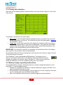
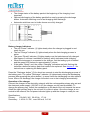
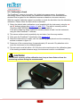
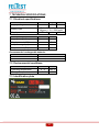
Feltest PresScan™ Instruction manual Version FPS-ENG-0804 CAUTION! Doing measurements of any kind on running paper machines is potentially dangerous and requires alertness, concentration and common sense. The products of Feltest Equipment BV are designed and constructed to be as safe as possible for their intended use. Feltest Equipment BV cannot be held responsible or liable in any way for injuries or damages that occurred using Feltest Equipment BV’s products. Edition FPS 0804, valid from firmware version 4.0.4 Feltest Equipment BV did their best to write a clear and accurate instruction manual. However, human errors can never be fully ruled out and we would be happy to receive your remarks. In case errors are contained in this manual, Feltest Equipment BV cannot be held liable for the consequences and/or damages related to such errors. As an effort to constantly improve its products, Feltest Equipment BV reserves the right to change the instrument‟s hardware, firmware or software without notice. Copyright © Feltest Equipment BV 2008. All rights reserved. 3 CONTENTS 1 Safety instructions .................................................................................................................... 7 1.1 Intended use......................................................................................................................... 7 1.2 Safety precautions ................................................................................................................ 7 1.3 Technical precautions ........................................................................................................... 8 1.4 Important direction for use .................................................................................................... 8 2 About the PresScan™ .............................................................................................................. 9 2.1 Introduction........................................................................................................................... 9 2.2 Scope of delivery .................................................................................................................. 9 2.3 Names of parts ..................................................................................................................... 9 3 Using the PresScan™ ............................................................................................................. 11 3.1 Switching the instrument on and off .................................................................................... 11 3.2 Functions of the red buttons ............................................................................................... 11 3.3 Opening the handle-bar ...................................................................................................... 11 3.3 Primary user interface ........................................................................................................ 12 3.4 Battery charger operating instructions ................................................................................ 12 3.5 The measurement .............................................................................................................. 15 3.5.1 Comparing measurements with the split-screen function ............................................. 16 3.6 Connecting the PresScan™ to the PC ................................................................................ 17 4 The PresScan™ menu ............................................................................................................ 19 4.1 Memory position number menu (Nr.) .................................................................................. 19 4.1.1 Cross Direction / Machine Direction (Nr. > CD/MD) ...................................................... 19 4.1.2 Before / After Conditioning (Nr. > CD/MD > BC/AC) ..................................................... 20 4.2 "Clear all" and "Clear actual" menu..................................................................................... 20 4.3 Scale menu ........................................................................................................................ 20 4.4 Setup menu ........................................................................................................................ 20 4.4.1 Language (Setup > Language)..................................................................................... 20 4.4.2 Date/Time (Setup > Date/Time) ................................................................................... 21 4.4.3 Calibration (Setup > Calibration) .................................................................................. 21 4.4.4 Display (Setup > Display) ............................................................................................. 21 4.4.5 Miscellaneous (Setup > Miscellaneous) ....................................................................... 21 4.4.6 Communication I/O port (Setup > Select I/O port) ........................................................ 22 4.4.7 Table List menu (Setup > Table List)............................................................................ 23 4.5 Table menu ........................................................................................................................ 23 5 Cleaning and Maintenance ..................................................................................................... 24 5.1 Replacing the rechargeable batteries ................................................................................. 24 5.2 Calibration check ................................................................................................................ 25 6 Trouble shooting ..................................................................................................................... 26 4 7 Technical specifications ......................................................................................................... 27 7.1 Electrical specifications....................................................................................................... 27 7.2 Environmental conditions.................................................................................................... 27 7.3 Identification plate............................................................................................................... 27 8 Technical Assistance.............................................................................................................. 28 9 Warranty terms........................................................................................................................ 29 Appendix A – communication protocol ..................................................................................... 31 A-1 Data format via UART (version 4.0) ................................................................................... 31 A-2 Command list ..................................................................................................................... 32 A-3 Measurement data format (version 2.0) ............................................................................. 33 A-4 Index Measure format (version 1.0).................................................................................... 34 5 Dear Customer, Thank you for choosing the PresScan™ as your felt moisture meter. This moisture meter is the result of 10 years research on microwave technology engineered to read water density, and over 8 years of daily heavy-duty testing. The PresScan™ is equipped with an state-of-the-art, innovative planar microwave sensor to read the water content in press fabrics, overcoming the limits of the traditional sensors. The record sampling rate of 1500 samples/second allows the highest possible resolution during FFT analysis on the fastest paper machines. The PresScan™ research project involved our labs, universities, "centres of excellence" and many service engineers who use our moisture meter every day and helped us to finetune the instrument. Feltest Equipment and Cristini Engineering have a policy of constant innovation. We carefully listen to our customers and continuously implement improvements in our products. This customer orientation led to the development of the PresScan™ MKIV, with new advanced features: New patented microwave sensor, with high speed digital data conversion; Far less influence of surface water compared to other moisture meters on the market; Sleeker and smaller sensor case; Temperature range extended to 60°C; Fully IP67 sensor; Double coating DuraCote™ anodising and HardCote™ paint, for un-matched wear resistance of the metal frame; New heavy-duty IP67 battery case; New handle-bar locking mechanism; New heavy-duty transportation case, built to military specs. Yours faithfully, the PresScan™ Development and Sales Team 6 1 SAFETY INSTRUCTIONS 1.1 Intended use The Feltest PresScan™ is developed only for use on press felts in running paper machines. With patented microwave technology the PresScan™ measures the amount of water that is contained in a press felt. The instrument is not intended, nor suitable for use on any other object or for any other application. 1.2 Safety precautions SAFETY WARNING! The PresScan™ is developed for use on dangerous machines (i.e. paper machines). The user of the PresScan™ must be properly trained and must take all possible precautions required to perform safe measurements at the machine where the instrument is used. SAFETY WARNING! Do not bend over into the machine. If you must lean against a safety fence, first check its stability. Do not ignore or remove safety constructions. ALWAYS FOLLOW THE SAFETY INSTRUCTIONS THAT APPLY FOR THE LOCATION WHERE THE MEASUEMENTS ARE DONE. SAFETY WARNING! The user must take all possible safety precautions to prevent entanglement of garments or of the PresScan™ and its accessories into the moving parts of the machine where the instrument is used at. SAFETY WARNING! Although especially designed for use in rough conditions, the PresScan™ must be carefully inspected before taking it into operation. Always verify if the PresScan™ is in perfect condition to perform safe measurements. It is particularly important to check for loose or damaged parts. 7 1.3 Technical precautions CAUTION! Before starting any measurement with the PresScan™, make sure that the connector is closed with the affixed screw cap! CAUTION! Only plug in the supplied battery charger into an electricity network that is up to standards. During the charging process, the user should be able to reach the power plug easily. CAUTION! Plug in the battery charger only indoors, in dry areas, away from heat sources (radiators, heaters, etc.). CAUTION! Do not use the PresScanTM while the battery charger is plugged into the electrical system, it will shorten the battery life. CAUTION! Use only authorised replacement batteries (see paragraph 7.1) 1.4 Important direction for use CAUTION! Prior to upgrading the instrument firmware, always consult Direct Service at +31 313 652 215. Wrong procedures might damage the control unit ROM. Updated versions of the “PresScan Host” software and the PresScan™ on-board firmware are available for free and can be requested per email at [email protected] 8 2 ABOUT THE PRESSCAN™ 2.1 Introduction The PresScan‟s innovative electronic design is based on a patented planar (flat) microwave sensor, managed by a dedicated microprocessor. This allows the instrument to be particularly non-sensitive to water on the surface of the press felt and to achieve the fastest sampling rate available (1500 samples per second). Unlike traditional sensors with a microwave resonance chamber, the PresScan™ microwave sensor is fully digital and not sensitive to temperature variations. Furthermore it is lightweight and very reliable. The instruments memory module of 32 MB has enough capacity to store up to 180 minutes of data. The graphical display shows the profile during the measurement in real-time and consumes only limited battery power. The PresScan™ is immediately ready for use after it has been switched on; it does not require any particular start-up calibration. 2.2 Scope of delivery The Feltest PresScan™ comes in a robust carrying case. In the case are: 1 PresScan™ portable moisture meter 1 battery charger with PresScan™-connector 1 USB cable to connect the PresScan™ to a computer with an USB port 1 RS232 serial cable to connect the PresScan™ to a computer with only a serial port 1 reference glass plate to verify the sensor's calibration 1 CD with PC software 1 user manual. 2.3 Names of parts Frontal view 1. Buttons to start and stop the measurement, hereafter called Measure buttons. 2 2. Handle-bar. 3. Display. 3 4 1 7 6 5 1 4. Navigation buttons, hereafter called ▲ and ▼ buttons. 5. “Enter” or accept button, hereafter called Enter 6. “Clear” or escape button, hereafter called Clear Figure 1 - front view 7. On/off button. 9 Top view 8. Assurance clip to lock/unlock the rotatable handle-bar . 8 Figure 2 - top view Bottom view 9. Lever to unlock the rotatable handle-bar. 9 10 10. Battery compartment. Figure 3 - bottom view Side view 11. Connector with screw cap to connect the PresScan™ with either a computer or the battery charger. 11 Figure 4 - side view 10 3 USING THE PRESSCAN™ 3.1 Switching the instrument on and off To switch on the PresScan™, press and hold the On/Off button shortly until the main screen shows up. Immediately after start-up, the PresScan™ is ready for a new measurement. To switch off the unit, press and hold the On/Off button again for at least 2 seconds. If the auto power-off function is enabled, the instrument will automatically switch off after a predefined period of non-use. 3.2 Functions of the red buttons Located around the display there are 4 red buttons plus one black On/Off button. In the handle-bar there are also 2 red buttons, the so-called Measure buttons. All red buttons are used to navigate through and control the functions of the PresScan™. The triangular cursor ► indicates which function currently has the focus and can be activated by the Enter button, it's value can be increased or decreased by the ▲ and ▼ buttons and the function can be exited by pressing the Clear button. The two Measure buttons that are located in the handle-bar have a double function. Primarily they are used to start and stop a measurement, but they are also used to activate the split screen function and to toggle between the upper and lower half of the split-screen. This function is explained in more detail in chapter 3.5.1. Figure 5 - locations of the red buttons 3.3 Opening the handle-bar For improved safety it is possible to open the upper half of the handle-bar. It can then be rotated and locked in several angles up to 180°, so that the user can keep more distance from the paper machine. To open up the handle-bar, first release the red assurance clip on top of the instrument (figure 2 on the previous page). The upper half of the handle bar can now move a little forward. Then hold down the lever at the base (figure 3, point 9) with one hand and move the handle bar to the desired position. Now release the lever and move the handle-bar a little until it clearly locks into a fixed position. To close the handle bar, hold down the lever again with one hand while closing the handlebar with the other, until the red assurance clip is securely locked. 11 3.3 Primary user interface After start-up, the display shows a screen similar to the one shown in figure 6. This is the main screen. Figure 6 - the main screen The display is divided into two main areas: Menu area: on the left hand side the available functions are listed. The cursor ► can be moved only in this area. The individual functions are described in chapter 4, the PresScan™ menu. Graph area: on the right hand side of the display the moisture profiles are shown, both during measurement in real-time and afterwards. This area also shows data related to the shown graph, like the average water content and temperature, the duration of the measurement plus the date and time. IMPORTANT: only when the cursor ► is completely on the left hand side of the display (as in figure 6) it is possible to start a measurement. On the bottom left corner the remaining time until 'memory full' is shown (in figure 6 this is 160 minutes and 45 seconds). The PresScan™ uses rechargeable NiMH batteries. The battery level is shown in the bottom right corner of the display. When the batteries are fully charged, the battery icon shows 3 bars (see figure 7). When no more bars are visible the batteries need to be charged urgently (see next chapter) Figure 7 3.4 Battery charger operating instructions The supplied battery charger / discharger has to be used to charge the batteries in the PresScan™. It has following features: Suitable for worldwide use thanks to a switch mode power supply (100-240 V AC) and exchangeable primary plug set. Microprocessor controlled charging. At the beginning of every charging a test cycle is run to identify and report defective battery packs. Short circuit detection and electronic protection against reversed polarity. 12 The charge status of the battery pack at the beginning of the charging is not important. Optional discharging of the battery pack before use by pressing the discharge button. Automatic switching over to fast charging after discharge. Automatic switching over to trickle charge once fully charged. Figure 8 - Battery charger indicators Battery charger indicators The red "Power" indicator (1) lights steady when the charger is plugged in and ready for use. The red "Charge" indicator (2) lights steady when the fast charging process is active. The green "Ready" indicator (3) lights steady once the batteries are fully charged. After approx 2 minutes it switches to flashing, which indicates trickle charging. When the instrument is connected to the charger, first the testing cycle is started and the green LED flashes for approximately 1 minute. If the green “Ready” and the yellow “Charging” indicators are both flashing this indicates a defective battery pack that needs to be replaced. See chapter 5.1 for instructions on replacing the battery pack. Press the “Discharge button” (5) for about two seconds to start the discharging process of the battery pack. The yellow "Discharge" indicator (4) lights steady during the discharging process (after pressing the yellow button). In some cases the discharging can take several hours. After a full discharge, the charger will switch over to fast charging automatically. Operation of the charger Connect the charger to the electricity network: with the exchangeable primary plug set and the electronic power supply (100-240 V AC) the charger can be used worldwide. To change the primary plug, unlock the mechanism on the back of the unit towards the arrow. Attach the right primary plug to the unit until it is clicks in place. Once the charger is connected to the network, the red power indicator lights up and the charger is ready for use. Specifications: Primary: 100-240 V AC, 50-60 Hz, 17 VA. Secondary: 1.45-14.5 V DC, max. 800 mA, 9.6 VA 13 WARNING! Use this charger only for the PresScan™ NiCd or NiMH battery packs. Danger of explosion if other types of batteries are charged. WARNING! Do not attempt to open the charger. WARNING! Keep the charger in a dry place (indoor use only). In order to avoid the risk of fire and/or electric shock, the charger must be protected against humidity and water. WARNING! Do not plug in the charger if there are any signs of damage to the housing, mains pins, cables or connectors. In case of a defect please return to an authorized service centre. WARNING! Keep the charger out of reach of children. WARNING! If the warning instructions are not followed, it may lead to damage to the charger or batteries or even to serious injury to the user. WARNING! The battery charger of the PresScanTM MkIV cannot be used for the previous versions PresScanTM versions (MkII-MkIII). WARNING! It is recommended to keep PresScan™ switched off during the battery recharging process. This guarantees longer life for the batteries. Environment Rechargeable batteries are not to be disposed in domestic waste. Return used batteries to your dealer or to a battery collection point for recycling. 14 3.5 The measurement After being switched on, the PresScan™ is immediately ready to start new measurements. A "set zero" procedure is not needed. The Measure buttons in the handle-bar can be set to work in two ways: keep one or both buttons pressed during the measurement or use them as an on/off switch. Refer to chapter 4.4.5 of this manual on how to set this option. When the PresScan™ is measuring the user will get 3 kinds of visual feedback: In the graph area the moisture profile is build in real-time. The word "MEASUREMENT" or "APPEND" (when resuming a measurement) is blinking A vertical "VU meter" (this option can be switched off, see chapter 4.4.5 in this manual). Figure 9 - the main screen during measurement During the first 25 seconds of a measurement the moisture profile is shown in real-time. After that period of time the profile is no longer refreshed. Only after the measurement is finished, the refreshed full profile is displayed. When the operator releases the Measure button the measurement is stopped. If the Measure button is pressed again, without changing the memory position number, the new data will be added to the actual measurement. Now the message "APPEND" is shown. To start a new measurement on a new memory position, bring the cursor ► to the Nr. Menu and press Enter to go to the numeric value (see chapter 4.1). Use the ▲ and ▼ buttons to change the memory position. Then press Enter again to set the Cross machine Direction / Machine Direction flag (chapter 4.1.1) and press Enter again to set the Before or After Conditioning flag (chapter 4.1.2). Then press Clear three times until the cursor ► is on the left hand side again and the new measurement can be started. When the CD/MD and BC/AC flags are not relevant for the operator there is also a faster way to start a new measurement in a new memory position. After the first measurement, jump to the numeric value of the Nr menu by pressing Enter once and then press Clear again (see figure 10). At this moment the numeric value has not changed yet, but as soon as one of the Measure buttons is pressed the PresScan will automatically use the next available free memory position. Figure 10 - fast way to go to the next free memory position 15 WARNING! The PresScan™ is developed for the use on dangerous machines (i.e. paper machines). The user must be properly trained, be aware of possible risks and dangers and must take all possible precautions required to perform safe measurements. WARNING! The PresScan™ user must take all the possible safety precautions, to prevent (protective) clothing or the PresScan™ and its accessories from being trapped or caught in the moving parts of the machine on which the instrument is used. WARNING! The use of mobile phones during the data acquisition can affect the measurement results. 3.5.1 Comparing measurements with the split-screen function With the split-screen function it is very easy to compare two stored profiles with each other. To start the split-screen function, first move the cursor ► to the memory position number section of the PresScan™ menu (figure 11). Select the first measurement number to be compared, using the ▲ and ▼ buttons. Figure 11 - select 1st measurement Then press one of the two Measure buttons in the handle-bar. The graph area is now split in an upper and lower half (figure 12) and also the cursor chances from ► into ▲ (to indicate/select the measurement for the top half of the screen) or ▼(for the bottom half). Figure 12 - top half shows nr. 1, bottom half shows nr. 2 16 As can be seen in the red circles in figure 12, on the left hand side of the graph area is a marker ▲ or ▼ displayed. This marker indicates which half of the split-screen is the active one. To change the profile shown in the bottom half of the screen, press one of the Measure buttons until the bottom half indicator is shown. Then use the ▲ and ▼ buttons to change the memory position number. Just press one of the Measure buttons in the handle-bar to toggle between the upper and bottom half . The measurement data (like date, time, mean value) that are shown are related to the active measurement. In the example of figure 12, measurement number 1 is shown on the top half of the screen and is recorded on 2 January 2008, measurement number 2 on the bottom half is of January 3rd 2008. To exit the split-screen function, just press the Clear button. 3.6 Connecting the PresScan™ to the PC The PresScan™ can be connected to the USB port or RS232 serial port of any personal computer with the Host PresScan™ software installed. Through this software the data transfer from and to the PresScan™ is fast and easily managed. The main functions are the data transfer of measurements and calibrations, updating languages and upgrading the firmware of the instrument (this operation is recommended for expert users only). In order to connect the instrument with the PC, follow these instructions: 1. Depending on which cable or port you want to use, connect the appropriate USB or RS232 cable between the PC and the PresScan™. 2. Set-up the communication port and speed on the instrument (see chapter 4.4.6), based on the settings of the Host PresScan software on the PC (see the Host PresScan instruction manual), or vice versa. 3. Return to the main screen of the PresScan™ (as shown after it is switched on). 4. Now use the Host PresScan™ software on the PC to establish a connection and transfer the data (for details see the Host PresScan™ manual). Appendix A describes the communication protocol for users who want to write their own communication software. 17 CAUTION! Use only the cables supplied with PresScan™! CAUTION! The firmware upgrade procedure can be only be carried out through the RS232 serial port of the PC. WARNING! During data transfer never switch off the instrument. This can cause the loss of all the saved data. WARNING! Before starting the firmware upgrade make sure that the batteries of the PresScan™ are fully charged! WARNING! Never switch off the PresScan™ during the firmware upgrade! This will damage the instrument's BIOS and ROM, making the instrument unusable. When the firmware operation is completed, a message on the PC will indicate to switch the PresScan™ off and on again. WARNING! An incorrect firmware upgrade, can damage the instrument BIOS and ROM, making it unusable. The instrument must then be sent for repair. It is advisable to perform firmware upgrades only under direct assistance from our technical support (tel. +31 313 652 215). 18 4 THE PRESSCAN™ MENU The ▲ and ▼ buttons are used to send the cursor ► to the desired function in the menu. To access the menu or submenu item, press Enter. To leave a (sub)menu item press the Clear button. The PresScan™ menu includes the following items: 1) 2) 3) 4) 5) 6) Memory position number Clear all Clear actual Scale Setup Table 4.1 Memory position number menu (Nr.) “Nr.” is a sequential number given to every saved moisture profile. When the PresScan™ is switched on, the instrument automatically shows the first available empty number. In figure 13 underneath the cursor ► is displayed before "Nr.", indicating that this function has the focus and can be activated by pressing the Enter button. Figure 13 - the Nr. menu To change the memory position number, either for a new measurement or to look at a profile that was saved before, just push the Enter button shortly. Now the cursor ► will move to the actual number (see figure 14) which can then be changed using the ▲ and ▼ buttons. Every new profile is saved in the first availabe free memory position. Figure 14 - "001" can be changed now To move the cursor ► back one level (for example from the situation in figure 14 to figure 13) press the Clear button. IMPORTANT: only when the cursor ► is on the left hand side of the display (as in figure 13) it is possible to start a measurement. 4.1.1 Cross Direction / Machine Direction (Nr. > CD/MD) For every memory position the user can add information about the measurement direction. CD stands for Cross machine Direction and MD stands for Machine Direction. This 'flag' can be set before starting the measurement and can also modified afterwards. To toggle between CD and MD, use the ▲ and ▼ buttons. Press Clear to get back one level to the memory position number or press Enter to go further to the BC/AC flag (see next page). Figure 15 - set CD or MD direction 19 4.1.2 Before / After Conditioning (Nr. > CD/MD > BC/AC) For every memory position the user can add information about the measuring position in relation to the felt conditioning system. BC stands for Before Conditioning and AC stands for After Conditioning. This 'flag' can be set before the measurement but can also modified afterwards. Figure 16 - set After / Before Conditioning To toggle between BC and AC, use the ▲ and ▼ buttons. When set, press Clear to go back one menu level. Only when the cursor ► is on the left hand side of the display (as in figure 8) it is possible to perform a measurement. 4.2 "Clear all" and "Clear actual" menu The "Clear all" function in the PresScan™ menu will erase all saved memory positions. This is done by placing the cursor ► to this menu item and to press Enter one time. Then the software asks for a confirmation (press Enter again) or exit the function without deleting the memory by pressing Clear. The "Clear actual" function will delete the profile that is currently shown in the graph area of the main screen. When the cursor ► is at the "Clear actual" menu item and Enter is pressed, the profile is deleted immediately. The memory position is now available for a new measurement. Figure 17 – "Clear all" menu item WARNING! During the memory deleting process never switch off the PresScan™! If it does happen, a warning message “MEMORYERROR 2” will appear at the next start up and the instrument will be blocked. To resume correct operation, wait a few seconds and follow the instructions shown on the display. 4.3 Scale menu With the Scale menu the range of the Y-axis of the graph is set. When the cursor ► is located at the this menu item, pressing Enter will toggle between the 3 available settings: 0 - 1000 g/m2, 0 – 2000 g/m2 and AUTO, where the software will automatically determine the range depending on the minimum and maximum values of the displayed profile. 4.4 Setup menu The Setup menu item in the main screen gives access to a submenu in which several settings can be adjusted. 4.4.1 Language (Setup > Language) The Language submenu item will show 5 selectable languages for the user interface of the PresScan™ instrument. Place the cursor ► on the required language and press Enter to select the language. To cancel the operation, press Clear. It is possible to load new and/or delete languages with the supplied PC software Host 20 PresScan™ (see the instruction manual of the Host PresScan™ software for more information). 4.4.2 Date/Time (Setup > Date/Time) With the Date/Time submenu the onboard clock can be set. The date and time values are stored with every measurement. Select the correct year, month, day, hour and minute by using the ▲ and ▼ buttons, to save the value press Enter. The cursor ► will than move to the next item, where the procedure is repeated. The new value can be saved by pressing the Enter button, pressing Clear will discard the change. 4.4.3 Calibration (Setup > Calibration) The Calibration screen will perform a frequency analysis of the microwave sensor, acquiring the calibration curves. This function is used by the manufacturer to analyse the operation and calibration; modification is not recommended to unqualified users. To cancel this operation, press the Clear button. For more information on calibration curves, please read chapter 4.4.7 (Table List menu). 4.4.4 Display (Setup > Display) The Display submenu accesses the options for the LCD screen. The options can be selected using the ▲ and ▼ buttons and press Enter to activate the them. Brightness: here the brightness of the screen's backlight can be set from 0 – 100%. Select the desired percentage with the ▲ and ▼ buttons and press Enter to accept or Clear to discard the change. Grid: by pressing Enter the grid in the graph area can be switched on or off respectively. WARNING! Obviously a higher backlight intensity will lead to higher energy consumption and thus reduced operating time. 4.4.5 Miscellaneous (Setup > Miscellaneous) The miscellaneous submenu allows the user to modify some additional features of the PresScan™. Select the desired item using the ▲ and ▼ buttons. Auto power-off: this option is used to set the PresScan‟s automatic power-off function when the instrument is not used for a pre-set amount of time. By pressing Enter the function will be enabled ("on") or disabled ("off"). Setting this option to ON will reduce the power consumption and as the PresScan™ is immediately ready for use after startup, it has no disadvantage. Time auto power-off: here the waiting period is set, before the PresScan™ switches off automatically (when "Auto power-off" is enabled). By pressing Enter the cursor ► will move to the numeric value. This value is the waiting time in minutes after the last button was pushed. Change the value with the ▲ and ▼ buttons and confirm with Enter or discard by using the Clear button. 21 Measurement: This function sets how the Measure buttons in the handle-bar will behave when the user wants to start/stop a measurement. Two options are available: o "PRESSED": the PresScan™ performs a measurement as long as one or two of the Measure buttons in the handle bar are being pressed. As soon as both buttons are released, the measurement will stop. o "ON/OFF": the PresScan™ will start a measurement immediately after one of the Measure buttons is pressed shortly. The measurement will only stop when one of the two Measure buttons in the handle bar is pressed again. VU Meter: this function adds a vertical bar on the right hand side of the graph area during the measurement. The "VU meter" shows drastic water changes faster than the real-time profile and it will also be better visible under wet conditions. Real-time graph Grid (on) Blinking visual feedback that data are being saved VU meter Figure 18 - the display during a measurement 4.4.6 Communication I/O port (Setup > Select I/O port) The PresScan™ can communicate with a PC through a serial (RS232) connection or through USB. After setting the connection type, also the communication speed must be set. Please note that the settings in the HOST PresScan™ computer software must be identical to the settings here, otherwise communication will fail! The procedure is as follows: 1. Port: Press the Enter button to enter this option. When the serial cable with the square 9 pins connector is used, select "RS232", when the USB cable is used select "USB" using the ▲ and ▼ buttons. Press Enter to confirm or Clear to exit without changes. 2. Data rate: Depending on the selected port, several communication speeds are available. Start with the highest possible speed and in case of communication problems reduce the speed. The following communication speeds are available: RS232: 19.2 kbs; 57.6 kbs, 115.2 kbs. USB: 19.2 kbs; 57.6 kbs; 115.2 kbs; 230 kbs; 460 kbs, 930 kbs. The data is transmitted with the following settings: BAUD RATE : 115200 bit/s (115.2 kbs, example) PARITY : none STOP BIT : 1 DATA BIT : 8 HANDSHAKING : none 22 3. Select Apply and press Enter to finalize the procedure and use the new communication settings. 4.4.7 Table List menu (Setup > Table List) The Table List submenu gives an overview of the available tables (or calibration curves) in the PresScan™. The instrument can load up to 4 tables, corresponding to 4 different calibrations. Each table is marked with an ID number and a short note. The empty memory positions (normally the 2 and 3), are marked by four empty digits. By default, table 4 is the calibration curve by which the electronic test results are converted into felt moisture values and table 1 is the sensor's unprocessed signal. Table 4 is necessary to build further personalized calibration curves, using the PresScan™ to scan the laboratory samples (please check the Host PresScan™ instruction manual for more details). With the provided Host PresScan™ software it is possible to load, unload and delete the tables loaded on the instrument. To return to the Setup menu, press Clear. WARNING! At least one table (calibration curve) must be loaded into the PresScan™, otherwise it will not be possible to perform measurements. 4.5 Table menu For every measurement it is possible to select one of the calibration curves. The desired table (or calibration curve) can be selected in the main screen (figure 19). As described in chapter 4.4.7 the PresScan™ can contain up to 4 calibration curves. If the PresScan™ is also used to measure the water content in other media than press felts (like for example paper board or forming fabrics) it is possible to use dedicated calibration curves. Please keep in mind that the PresScan™ is solely intended and designed for the use Figure 19 - Table menu item on press felts (see chapter 1.1, intended use)! By default, table 4 is the pre-set calibration for use on press felts (as shown in figure 19). To switch over to another table move the cursor ► to the Table menu and press Enter to select. With the ▲ and ▼ another table can be select, press Enter to confirm or Clear to exit without changing the table. WARNING! For felt moisture measurements it is recommended to use only the default table 4, supplied by the manufacturer. Otherwise, use only personalized tables that are created with the Host PresScanTM software. 23 5 CLEANING AND MAINTENANCE CAUTION! Before storing the instrument, carefully clean and dry the outside of the unit. CAUTION! Always close the PresScan's connector with the provided screw cap before starting a measurement. The connector is ONLY waterproof with the mounted screw cap! CAUTION! Do NOT open the instrument for any reason, this will void the warranty! Only the battery compartment is excluded from this disclaimer. 5.1 Replacing the rechargeable batteries The PresScan™ is using rechargeable NiMH batteries. As with all rechargeable batteries, the number of times that they can be recharged is limited. If the batteries wear out very fast after a full charge, it is time to replace them. In order to replace the batteries, proceed as follows: 1. Switch off the PresScan™; 2. Open the bottom cover (see figure 20) to access the battery compartment, by removing all the screws with an appropriate screwdriver; 3. Unlock the battery pack by releasing the clamp; 4. Disconnect the battery pack; 5. Replace the exhausted battery pack with new batteries of the same type (see chapter 7.1) or equivalent, paying attention to the polarity and connections. A completely new battery pack is available at Feltest Equipment under product code 200107; 6. Reconnect the battery pack; 7. Lock the battery pack with the clamp; 8. Close the battery compartment with the cover, applying moderate force to tighten the screws; tight the screws in a diagonal mode as shown in figure 20 in order to evenly distribute the pressure on the compartment cover. 1 3 4 2 Figure 20 – closing the battery compartment 24 5.2 Calibration check The PresScan™ uses an innovative, fully digital microwave sensor. Its patented technology makes it electronically very stable and insensitive to the thermal/electric deviation that is typical for the traditional resonance chamber microwave sensors. With the supplied calibration glass it is possible to check the deviation from the laboratory calibration. Please follow the instructions underneath: 1) Select the default table (calibration curve) supplied with the instrument, using the ▲ and ▼ buttons (please see chapter 4.5 and 4.4.7). The table is normally named “PresScan MKIV SERIALNO ....” , by default set as table 4. If the above table has been modified or erased, please re-load it on the instrument, using the Host PresScan™ software; 2) The sensor surface must be perfectly dry and clean, free from any residue. 3) Fully open the PresScan™ handle-bar (see chapter 3.3). 4) Place the instrument on a table, with the calibrating glass placed over the measuring surface as shown in figure 21. 5) Press one of the measure keys for approximately 15 seconds. Pay attention not to move the instrument or the calibrating glass. 6) The test result must fall within ± 5% from the value mentioned on the calibration glass. If the reading exceeds tolerance range, the instrument must be re-calibrated. CAUTION! For the best accuracy of the calibration test, keep a clear distance from the measuring surface during the measurement! Figure 21 - checking the calibration with the glass plate 25 6 TROUBLE SHOOTING Below some brief indications for the PresScan™ troubleshooting: The PresScan™ fails to respond to the commands Try to switch off the instrument, using the On/Off button; if the instrument is not responding, disconnect and re-connect the battery pack (see chapter 5.1). If the message MEMORYERROR 2 is shown, wait a few seconds and follow the instructions on the display. This error can occur when the instrument is switched off while the memory is read or deleted (see chapter 4.2). The batteries fail to recharge Make sure that the battery charger cable is correctly connected to the PresScan™ connector, located in the base of the instrument. Check that the battery charger is correctly connected to the electricity network, the red LED “Power” must be on. Check if the battery pack is still in good condition; if the green and yellow LED of the battery charger are flashing simultaneously (see chapter 3.4) the battery pack is defective and needs to be replaced (see chapter 5.1). Keep the instrument switched off during the recharging process. Replace the exhausted battery pack (see chapter 5.1). PresScan™ fails to connect to the computer Check that if the cable is correctly connected to both the computer and the PresScan™. Make sure that the used cable (with USB or serial RS232 connector) matches the settings in both the PresScan (see chapter 3.6) and the Host PresScan™ software. Make sure that the communication settings, especially the communication speed, in both the PresScan™ and the Host PresScan™ software are identical (see chapter 3.6). Check if the correct COM port is selected in the Host PresScan™ application. Especially when the USB cable is used, the computer creates a "virtual com port" when the PresScan™ is connected. In the Host PresScan™ software this "virtual com port" must be selected as the active com port (see the Host PresScan™ manual). Also make sure that no other application on the computer is using the same com port. In that case close the other application. 26 7 TECHNICAL SPECIFICATIONS 7.1 Electrical specifications Electrical parameter Supply voltage Battery type Supply current Battery charger parameter Supply voltage (AC) Supply current (AC) Output voltage (DC) Output current (DC) Min. Typ. Max. 5.7 V 7.2 V 8.4 V Pack of 6, NiMH, size AA Mignon, 1.2 V, 2500 mAh 350 mA 900 mA Min. 110 V 1.45 V Max. 240 V 17 VA 14.5 V 800mA Recommended rechargeable batteries Brand Model SANYO HR-3U 1.2V 2500 mAh ANSMANN DIGITAL 2600 mAh 7.2 Environmental conditions Environmental parameter Operating temperature Storage temperature Min. 0 °C -10 °C Max. +60 °C +85 °C 7.3 Identification plate 27 8 TECHNICAL ASSISTANCE All countries of the world, excluding the countries mentioned underneath. FELTEST EQUIPMENT BV Bijenkorf 55 NL-6961 PA Eerbeek - The Netherlands Phone: +31 313 652 215 Fax: +31 313 654 068 e-mail: [email protected] Web: www.feltest.com Contact: Mr. Marcel Lensvelt Canada, United States, Mexico CRISTINI NORTH AMERICA INC. 700, Cristini Blvd Lachute QC J8H 4N3 – Canada Phone: +1 450 562 5511 Fax: +1 450 562 5055 e-mail: [email protected] Web: www.cristini.com Contact: Mr. John Feola Australia, China GIUSEPPE CRISTINI S.P.A. Via Bombardieri, 5 I-24020 Fiorano al Serio (BG) - Italy Phone: +39 035 715111 Fax: +39 035 711451 e-mail: [email protected] Web: www.cristini.com Contact: Ms. Michela Dentella Japan NOMURA SHOJI CO., LTD 3-15-2, Nihonbashi, Chuo-Ku 103-0027 Tokyo – Japan Phone: +81 3 3275 8001 Fax: +81 3 3275 8005 e-mail: [email protected] Web: www.nomurashoji.com Contact: Mr. Masaru Futaba Russia UNITSERVICE LTD Basseynaya, 53 196135 St. Petersburg – Russia Phone: +7 812 3350085 Fax: +7 812 3350085 e-mail: [email protected] Contact: Mr. Nikolay Syomin 28 9 WARRANTY TERMS Feltest Equipment BV warrants the proper execution of the agreed performance (as described in chapter 1 of this manual) for a period of twelve months after delivery. Feltest Equipment BV warrants that the goods are of good quality and free from defects. Feltest Equipment BV shall only be liable under this warranty if the product is used under normal use and service conditions and in a proper manner as specified in the enclosed instructions. All other warranties are excluded. During the warrant term, this warranty applies to the original buyer of the product and to each transferee owner of the product. No warranty is given for defects that are the result of: a. normal wear and tear; b. injudicious use; c. non-maintenance or defective maintenance; d. installation, alteration, assembly, modification or repair by Buyer or by third parties. e. delivered items of goods that were not new at the moment of delivery; No warranty is given for consequential loss or damage, for misusing and/or abusing and/or improperly maintaining the product in a manner contrary to Feltest Equipment BVs instruction manual. If it transpires that the delivery or the product has not been sound and there is not a defect as mentioned above Seller may choose whether: a. to repair the item of goods; b. to replace the item of goods; c. to provide the customer with a credit note for a proportionate part of the invoiced amount. For warranty Services, buyer must return the product at Buyer‟s costs and risk to Feltest Equipment BV‟s site at the following address: Feltest Equipment B.V. Bijenkorf 55 6961 PA Eerbeek The Netherlands Please check on the website www.feltest.com under "contact" and "delivery address" if this address is still applicable. Buyer may no longer invoke an instance of non-performance if he does not lodge a written claim with Feltest Equipment BV within one month of the date on which he discovers the defect or could reasonably be expected to discover it. 29 CE DECLARATION The firm S.A. Giuseppe Cristini S.p.A. with registered office located in Via Quintino Sella 4, Milan declares under its own responsibility that the product: PRESSCAN™ To which this declaration is reported and conforms to the following rule: Rule CEI EN 61326-1 First edition. Number 4440 – April 1998 and variation A1 Number 5170 – May 1999 and A2 Number 6392 – January 2002. therefore responds to the fundamental requirements of the Directives: Directive for Electromagnetic Compatibility CEE 89/336 and following updates Directive for Low Tension CEE 72/23 and following updates Fiorano al Serio, 21/12/2005 (place and date) 05 (last two digits of the approval year) Giovanni Cristini (stamp, name and signature of the person responsible for the production) 30 APPENDIX A – COMMUNICATION PROTOCOL Underneath is a description of the data communication protocol, that can be used to develop software that can communicate with the PresScan™ directly to download the test results. This information is only intended to download the test results. Firmware upgrades must always be done with the supplied Host PresScan™software. A-1 Data format via UART (version 4.0) Communication PresScan™ PC Message Fixed fields 31 n AWAITING ACK FROM PC (5Ah) Data Length HI byte HI word (n) Data Length LO byte HI word (n) Data Length HI byte LO word (n) Data Length LO byte LO word (n) Ser. Number strumento HI Ser. Number strumento LO Ver. Number HI Ver. Number LO Mea/Ca/Tab Number HI Mea/Ca/Tab Number LO PAR3 (1 Byte) PAR2 (1 Byte) PAR1 (1 Byte) xx ?? ?? ?? ?? ?? ?? ?? ?? ?? ?? ?? ?? ?? CMD (1 Byte) Byte [1] =0x55 Byte [0] =0x55 55 55 Data DATA (<= 65520 Bytes) Header Communication PC PresScan Message Data Fixed fields n ATTESA ACK da SENSORE (5Ah) Data Length HI byte HI word (n) Data Length LO byte HI word (n) ?? ?? ?? Data Length HI byte LO word (n) ?? Data Length LO byte LO word (n) ?? Mea/Ca/Tab/Lan Number HI ?? Mea/Ca/Tab/Lan Number LO ?? PAR3 (1 Byte) ?? PAR2 (1 Byte) PAR1 (1 Byte) xx ?? CMD (1 Byte) Byte [1] =0x55 Byte [0] =0x55 55 55 DATA (<= 65520 Bytes) Header A-2 Command list Command (field CMD) Description Transmission direction 00h 01h 02h 03h 04h 05h 06h 07h 08h 09h 0Ah 0Bh 0Ch 0Dh 0Eh 0Fh 010h 011h 012h 013h 014h 015h Host control Exit Host control Request measures index Request tables index Request calibrations index Request languages index Request measure Request calibration Request table Send table Send language Cancel table Cancel language Cancel measure Cancel calibration Send measure Send calibration Send table Send measures index Send tables index Send calibrations index Send languages index PC PresScan PC PresScan PC PresScan PC PresScan PC PresScan PC PresScan PC PresScan PC PresScan PC PresScan PC PresScan PC PresScan PC PresScan PC PresScan PC PresScan PC PresScan PresScan PC PresScan PC PresScan PC PresScan PC PresScan PC PresScan PC PresScan PC 32 A-3 Measurement data format (version 2.0) … … ID TAB high … … 19 TAB DESCR high 0 Data low BLOCK 0 Hsec SEC MIN HOUR … … … … Hsec SEC MIN TABLE BLOCK ID TAB low BLOCK N In the command header, the total number of bytes corresponds to the byte highlighted in blue in the following table: 0 TAB DESCR low 0 Data High … … … … ... … … … … … … … … … … … … … … … … … … … … … … 4095 Data low 4095 Data high CS DAY/ YEAR MONTH YEAR TEMP LOW TEMP HIGH NUM BYTE LOW NUM BYTE HIGH TYPE (m– a) B1 B2 B3 B4 … … BX CS … … … … … … … … … … … … … … … … … HOUR DAY/ YEAR MONTH YEAR TEMP LOW TEMP HIGH NUM BYTE LOW NUM BYTE HIGH TYPE (m– a) B1 B2 B3 B4 … … BX CS The CS of each block refers to the byte highlighted in Bold. After each CS the instrument awaits an acknowledgement 5A prior to transmit the next block. The field TYPE describes the measurement properties or 'flag' according the following definition: BIT7 x BIT6 x X: M/A: BIT5 x BIT4 x BIT3 X BIT2 BC/AC BIT1 MD/CD BIT0 M/A not used 0= Measure ; 1=Append (applies to a measurement that was temporarily stopped because the Measure button was released and then continued). 0=MD (Machine Direction profile); 1=CD (Cross Machine Direction profile) 0=BC (Before Conditioning); 1=AC (After Conditioning) MD/CD: BC/AC: When a measure is requested and its calibration table is no longer available on the instrument, it will be sent an “empty” table block with the following data format, where the byte are all placed at „0x00‟: ID TAB low = 0 1 0 0 1 1 ID TAB high =0 1 0 … CS = 0 8217 byte 33 A-4 Index Measure format (version 1.0) The total number of bytes in the command header corresponds to the byte showed in this table (8*100=800). If the measure is empty, the instrument transmits 11 “X” characters. 1 Hsec SEC MIN HOUR DAY/YEAR MONTH YEAR 2 Hsec SEC MIN HOUR DAY/YEAR MONTH YEAR … … … … … … 100 Hsec SEC MIN HOUR DAY/YEAR MONTH … … 34 YEAR NOTES 35