1
SnapGear VPN Router Family
User Manual
Rev: August 20, 2002
7984 South Welby Park Drive #101
Salt Lake City, Utah 84084
Tel: 801-282-8492
Fax: 801-282-8496
Introduction
Table of contents
1.
Introduction...............................................................................................1
Document conventions .......................................................................................... 4
Installing and configuring your SnapGear appliance ............................................. 5
Your SnapGear appliance ..................................................................................... 6
SnapGear appliance features ................................................................................ 8
2.
Getting started ........................................................................................11
New networks ...................................................................................................... 12
Setup wizard ........................................................................................................ 13
System requirements........................................................................................... 13
Configuring the SnapGear appliance on your network ........................................ 14
Initial setup using Linux ....................................................................................... 17
SnapGear quick setup ......................................................................................... 20
Configuring the PCs on your network .................................................................. 24
3.
Connecting to the Internet .....................................................................26
Physically connect modem device....................................................................... 26
Select Internet connection ................................................................................... 27
Internet failover .................................................................................................... 30
Configure PCs to use SnapGear appliance Internet gateway ............................. 33
Establishing the connection ................................................................................. 33
4.
Dial-in server configuration ...................................................................34
Dial-in setup......................................................................................................... 36
Dial-in user accounts ........................................................................................... 38
Remote user configuration................................................................................... 41
Introduction
5.
Network configuration............................................................................47
IP configuration.................................................................................................... 47
Advanced IP configuration................................................................................... 49
DHCP server........................................................................................................ 51
Advanced networking .......................................................................................... 53
6.
Firewall ....................................................................................................54
Incoming access .................................................................................................. 54
Outgoing access .................................................................................................. 58
Firewall rules........................................................................................................ 59
Intrusion detection and blocking .......................................................................... 60
Content filtering.................................................................................................... 62
7.
Virtual Private Networking .....................................................................65
PPTP client setup ................................................................................................ 66
PPTP server setup............................................................................................... 68
IPSec setup ......................................................................................................... 81
IPSec interoperability........................................................................................... 86
8.
System.....................................................................................................87
Time server.......................................................................................................... 87
Password ............................................................................................................. 87
Diagnostics .......................................................................................................... 88
Advanced............................................................................................................. 88
Flash upgrade...................................................................................................... 89
RESET button...................................................................................................... 89
9. Technical support .......................................................................................90
Appendix A – LED status patterns.................................................................91
Introduction
Introduction
1. Introduction
This chapter provides an overview of your SnapGear appliance’s features and
capabilities, and explains how to install and configure your SnapGear appliance.
The SnapGear appliance enables small to medium-sized businesses to securely
interconnect computers on your office network to the Internet. The SnapGear appliance
has all the features a business needs to take full advantage of the Internet. Regardless of
whether you are connecting to the Internet for the first time or looking for a cost-effective
and safe VPN solution, the SnapGear appliance will meet your needs.
The SnapGear appliance simply and securely interconnects your network to the Internet
using a robust embedded firewall. Shielded behind a NAT gateway, your office
computers are protected from outside threats. The SnapGear appliance filters and
checks data packets to prevent unauthorized Internet applications accessing your
network.
The SnapGear appliance provides your network with a Virtual Private Network (VPN)
server. A VPN enables remote workers or branch offices to securely access your
company network to send and receive data at a very low cost. With the SnapGear
appliance, you can remotely access your office network securely using the Internet. The
SnapGear appliance can also connect to external VPNs as a client.
Using your SnapGear appliance, everyone on your office LAN can access the Internet
using a single connection. Your entire network can log on to the Internet using only one
ISP account through one analog modem, DSL or ISDN line. This eliminates separate
connections and ISP charges for each individual user. Using a dial-in modem connected
to your SnapGear appliance, your remote staff can also securely access your office
network using direct-dial.
This manual describes how to take advantage of the features of your SnapGear
appliance, including setting up a VPN, a secure firewall and an Internet connection. It
also describes how to set up the SnapGear appliance on your existing or new network
using the web configuration interface.
Installing your SnapGear appliance into a well-planned network is quick and easy.
Although network planning and design is outside the scope of this manual, please take
the time to plan your network prior to installing your SnapGear appliance.
Introduction
1
Terminology
This section explains terms that are commonly used in this document.
Term
Meaning
ADSL
Asymmetric Digital Subscriber Line. A technology allowing highspeed data transfer over existing telephone lines. ADSL supports
data rates between 1.5 and 9 Mb/s when receiving data and between
16 and 640 Kb/s when sending data.
BOOTP
Bootstrap Protoco. A protocol that allows a network user to
automatically receive an IP address and have an operating system
boot without user interaction. BOOTP is the basis for the more
advanced DHCP.
DHCP
Dynamic Host Configuration Protocol. A communications protocol
that assigns IP addresses to computers when they are connected to
the network.
DNS
Domain Name System that allocates Internet domain names and
translates them into IP addresses. A domain name is a meaningful
and easy to remember name for an IP address.
DUN
Dial Up Networking.
Ethernet
A physical layer protocol based upon IEEE standards.
Extranet
A private network that uses the public Internet to securely share
business information and operations with suppliers, vendors,
partners, customers, or other businesses. Extranets add external
parties to a company’s intranet.
Failover
A method for detecting that the main Internet connection (usually a
broadband connection) has failed and the SnapGear apliance cannot
communicate with the Internet. If this occurs, the SnapGear appliance
automatically moves to a lower speed, secondary Internet
connection.
Fall-forward
A method for shutting down the failover connection when the main
Internet connection can be re-established.
Firewall
A network gateway device that protects a private network from users
on other networks. A firewally is usually is installed to allow users on
an intranet access to the public Internet without allowing public
Internet users access to the intranet.
Gateway
A machine that provides a route (or pathway) to the outside world.
Hub
A network device that allows more than one computer to be
connected as a LAN, usually using UTP cabling.
IDB
Intruder Detection and Blocking. A feature of your SnapGear VPN
Router that detects connection attempts from intruders and can also
optionally block all further connection attempts from the intruder’s
machine.
Internet
A worldwide system of computer networks - a public, cooperative,
and self-sustaining network of networks accessible to hundreds of
Introduction
2
Term
Meaning
millions of people worldwide. The Internet is technically distinguished
because it uses the TCP/IP set of protocols.
Intranet
A private TCP/IP network within an enterprise.
IPSec
Internet Protocol Security. IPSec provides interoperable, high quality,
cryptographically-based security at the IP layer and offers protection
for network communications.
LAN
Local Area Network.
LED
Light-Emitting Diode.
MAC address
Ethernet address set by the manufacturer.
Masquerade
The process when a gateway on a local network modifies outgoing
packets by replacing the source address of the packets with its own
IP address. All IP traffic originating from the local network appears to
come from the gateway itself and not the machines on the local
network.
NAT
Network Address Translation. The translation of an IP address used
on one network to an IP address on another network.
Net mask
The way that computers know which part of a TCP/IP address refers
to the network, and which part refers to the host range.
NTP
Network Time Protocol (NTP) used to synchronize clock times in a
network of computers.
PAT
Port Address Translation. The translation of a port number used on
one network to a port number on another network.
PPP
Point-to-Point Protocol. A networking protocol for establishing simple
links between two peers.
PPPoE
Point to Point Protocol over Ethernet. A protocol for connecting users
on an Ethernet to the Internet using a common broadband medium
(e.g. single DSL line, wireless device, cable modem, etc).
PPTP
Point to Point Tunneling Protocol. A protocol developed by
Microsoft™ that is popular for VPN applications. Although not
considered as secure as IPSec, PPP is considered “good enough”
technology. Micorosoft has addresses many flaws in the original
implementation.
Road warrior
A remote machine with no fixed IP address.
Router
A network device that moves packets of data. A router differs from
hubs and switches because it is “intelligent” and can route packets to
their final destination.
Subnet mask
See “Net mask”.
Switch
A network device that is similar to a hub, but much smarter. Although
not a full router, a switch partically understands how to route Internet
packets. A switch increases LAN efficiency by utilizing bandwidth
more effectively.
TCP/IP
Transmission Control Protocol/Internet Protocol. The basic protocol
Introduction
3
Term
Meaning
for Internet communication.
TCP/IP address
Fundamental Internet addressing method that uses the form
nnn.nnn.nnn.nnn.
UTC
Coordinated Universal Time.
UTP
Unshielded Twisted Pair cabling. A type of Ethernet cable that can
operate up to 100Mb/s. Also known as Category 5 or CAT 5.
VPN
Virtual Private Networking. When two locations commmunicate
securely and effectively across a public network (e.g. the Internet).
The three key features of VPN technology are privacy (nobody can
see what you are communicating), authentication (you know who you
are communicating with), and integrity (nobody can tamper with your
messages/data).
WAN
Wide Area Network.
WINS
Windows Internet Naming Service that manages the association of
workstation names and locations with IP addresses.
Document conventions
This document uses different fonts and typefaces to show specific actions.
Warning
Warning text like this highlights important issues.
Bold text in procedures indicates text that you type, or the name of a screen object (e.g.
a menu or button).
Introduction
4
Installing and configuring your SnapGear appliance
This manual contains instructions for installing and configuring your SnapGear appliance
on your network. The basic steps and related chapters are:
Step
Chapter
1. Interconnect the SnapGear appliance
and PCs on a local area network.
Chapter 2, Getting started
2. Connect the telecommunications
hardware/modem for dial-in/dial-out
Internet access.
Chapter 3, Connecting to the Internet
3. Set up the network IP addresses and
firewall.
Chapter 2, Configuring the SnapGear
appliance on your network
4. Set up Internet hardware and Internet
account and connect to the Internet.
Chapter 3, Connecting to the Internet
5. Set up users’ security dial-in/dial-out
VPN.
Chapter 4, Dial-in server configuration
Chapter 6, Filtering and Security Groups
Chapter 7, Virtual Private Networking
Introduction
5
Your SnapGear appliance
The following items are included with your SnapGear appliance:
•
Power adapter
•
Installation CD
•
Printed Quick Install guide
•
Cabling including
o
1 normal UTP cable (blue color).
o
1 “cross-over” UTP cable (either gray or red color). If you have the LITE+
you will receive two straight through cables (blue color).
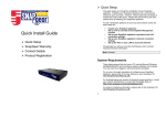
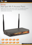
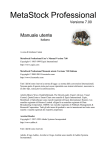
LEDs
The front and rear panels contain LEDs indicating status. The front panel LEDs are
illustrated in the following figure and detailed in the following table.
Figure 1.1 SnapGear SOHO+/PRO front panel LEDs
Label
Activity
Description
POWER/PWR
On
Power is supplied to the SnapGear appliance.
System/SYSTEM
Flashing
System flashes once every second when the
SnapGear appliance is operating correctly.
On
If the System LED is on and not flashing, an operating
error has occurred. In this situation, the other LEDs
form a diagnostic pattern indicating the failure.
Online/ONLINE
On
Indicates a valid Internet connection is present.
COM 1, 2
Flashing
For either of the SnapGear appliance COM ports,
these LEDs indicate receive and transmit data.
VPN
On
Virtual Private Networking is enabled.
Introduction
6
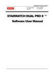
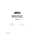
The rear panel contains the connector ports for the LAN (LAN) and modem (COM1,
COM2), LAN 10BaseT status LEDs, WAN 10BaseT status LEDs, the reset button and
power inlet.
The upper LEDs represent the “Link” condition, where a cable is connected correctly to
another device (e.g. a cable modem). The lower light represents the “Activity” as per the
front panel.
Figure 1.2 SnapGear appliance back panels
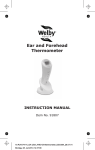
The following figure shows how your SnapGear appliance interconnects . If you are using
the SnapGear LITE, a secondary hub/switch is not required as this unit has a 4-port
Ethernet switch.
Figure 1.3 Network interconnections
Introduction
7
SnapGear appliance features
• Software features
•
Network Address Translation (NAT) firewall that isolates the LAN from the Internet
and offers network access control and filtering.
•
DHCP server and client that ensure simple and flexible IP network configuration.
•
PPTP VPN server that provides communications to remote users running
standard Windows VPN client software.
•
PAP, CHAP, MSCHAPv2, RADIUS and TACACS+ tunnel authentication
(RFC1334, RFC1994).
•
Transparent tunnel support for PPTP. IPSec pass through.
•
Dial-in remote access with PAP, CHAP, MSCHAPv2, RADIUS and TACACS+
authentication.
•
Dial-on-demand for outgoing Internet connections.
•
Wizard setup and browser-based management and configuration.
•
Flash upgradeable firmware that allows you to download and install the latest
protocols and security software using the web.
•
Connect Windows PCs, Macintoshes, Linux and Unix workstations - basically
anything that talks IP - to the Internet.
Introduction
8
Internet link features
•
Connect to the Internet using an external cable modem, DSL, dial-up or ISDN
modem.
•
Serial ports (COM1, COM2) connect to the Internet using an external modem or
ISDN T/A. The LITE and LITE+ models have a single serial port.
•
10baseT Ethernet port (Internet) that connect to the Internet using a cable or
ADSL modem.
•
Front panel serial status LEDs (for TXD/RXD).
•
Online status LEDs (for Internet/VPN).
•
Rear panel Ethernet LEDs (Link Transmit/Receive).
LAN link features
•
•
For the SnapGear SOHO+ and PRO models:
o
10BaseT LAN port to connect to the local network Ethernet hub.
o
Rear panel Ethernet LEDs (Link Transmit/Receive).
For the SnapGear LITE and LITE+ models:
o
10/100BaseT LAN port to connect to the local network.
Dial-in connection features
If you are using the SnapGear SOHO+ and PRO, external modems may be attached to
the serial ports for dial-in connection.
Introduction
9
Environmental features
•
External power adaptor (voltages/current depend on individual models).
•
Front panel status LEDs: Power Test.
•
Operating temperature between 0° C and 40° C.
•
Storage temperature between -20° C and 70° C.
•
Humidity between 0 to 95% (non-condensing).
Introduction
10
2. Getting started
Your SnapGear appliance provides a secure, simple gateway to connect PCs and other
devices on your local network to the outside world. This chapter provides step-by-step
instructions for connecting the SnapGear appliance to your LAN. The procedures in this
section are similar to the steps in the SnapGear Quick Install Guide, which you may
prefer to use if you are in a hurry.
Using an Ethernet cable, connect the SnapGear appliance’s LAN Ethernet port (marked
LAN) to a spare port on the existing network hub. At this stage do not switch on the
power to your SnapGear appliance.
Your SnapGear appliance comes with an in-built DHCP server that can automatically
assign IP addresses to other devices on the network. If you have an existing network,
you may already have an active DHCP server and the PCs and devices on the network
may already have IP addresses assigned. To simplify the installation in existing networks,
your SnapGear appliance ships without an initial IP address and without the DHCP
server activated.
Note
The following steps detail the initial setup procedure for networks with at least one Windows
workstation. If you wish to perform the setup procedure using a Linux box, skip to the
section called Initial setup using Linux later in this chapter.
Getting started
11
New networks
If you do not have an existing LAN, use the following steps to get started:
1. Install the hub according to its instructions. The LITE+ has an advanced Ethernet
switch that makes a hub unnecessary for small networks.
2. Install an Ethernet adapter and software driver in at least one of the PCs to be
networked.
3. Assign an IP address for your PC so the SnapGear appliance can be configured
on the network. From the Start menu, select Settings, Control Panel, Network
and click the Configuration tab (or Protocols if using NT).
4. Ensure that the TCP/IP networking protocol is installed. If not, click Add (then
Protocol if using Windows 95/98, Microsoft then TCP/IP). Your PC will then
reboot.
5. Highlight TCP/IP (followed by your Ethernet adapter’s name if using 95/98) and
click Properties.
6. In the IP Address panel, select Specify an IP Address. Private network
addresses should be in the ranges:
10.0.0.0 - 10.255.255.255 (10/8 prefix)
172.16.0.0 - 172.31.255.255 (172.16/12 prefix)
192.168.0.0 - 192.168.255.255 (192.168/16 prefix)
7. Enter the value into the IP Address field followed by a number (1-255) to identify
your PC (e.g. 10.0.0.45). You may have to reboot at this point.
8. Connect the SnapGear appliance and the PC to the hub and continue with the
following steps.
When you reach the final stages of setting up your SnapGear appliance, we
recommend that you take advantage of using the SnapGear appliance as a
DHCP server and set up the PCs on your network to dynamically receive TCP/IP
configuration information.
Getting started
12
Setup wizard
Your SnapGear appliance ships with a Windows installation program called SnapGear
Setup Wizard. If you are using statically pre-assigned IP addresses on your network (i.e.
there is a static network with no active DHCP server), the Setup Wizard will help assign
an IP address to the SnapGear appliance.
On DHCP enabled (i.e. dynamic) networks , the Setup Wizard will locate the IP address
assigned to your SnapGear appliance. The Setup Wizard will also provide the option to
configure the Internet connection setup and change the password for the SnapGear
appliance.
System requirements
You can run the Setup Wizard from any PC on the network running Windows 2000,
Windows XP, Windows ME, Windows NT 4 or Windows 95/98.
If you are using Windows 95 you must have the MS Dial Up Networking 1.3 update
(msdun13.exe) installed.
If you are using an early version of Windows 95 (i.e. pre-OSR2), you must install the
Winsock 2.0 update (w95w2setup.exe). If you are using Windows NT, you must be
logged in as administrator to run the Setup Wizard.
Getting started
13
Configuring the SnapGear appliance on your network
To configure the SnapGear appliance on your network:
1. Apply power to the SnapGear appliance. When the SnapGear appliance is
powered on and it has no IP address, all the front panel LEDs will flash (except
POWER). The LEDs remain flashing until an IP address is acquired.
2. Insert the SnapGear appliance Installation CD into the CD drive of any Windows
PC on your network that meets the system requirements. From the Start menu,
select Run and type z:\setup (where z is the letter of your CD drive).
3. Select the directory and Start menu group where the software utilities for your
SnapGear appliance will be installed.
4. The wizard will search the network for your device. Once the wizard locates your
device, you will be asked to enter an IP address (see the section called Static
networks).
If your network already has a DHCP server (i.e. a dynamic network), an IP address is
automatically assigned to your SnapGear appliance and the LEDs will stop flashing. The
Setup Wizard will locate your SnapGear appliance on the network.
Getting started
14
Static networks
The Setup Wizard will ask you to enter an IP address for your SnapGear appliance.
Select an unused IP address to assign to the SnapGear appliance (e.g. 10.0.0.199). The
first three fields are automatically completed, based on the IP address and net mask of
the local machine.
Ensure that the SnapGear appliance is powered on and plugged into the network, then
click OK. The Setup Wizard will check if the IP address is available. If the IP address is
available, it is assigned to the SnapGear appliance, otherwise you will be asked to select
another address.
Figure 2.1 Setup wizard IP setup
The LEDs on the front panel of the SnapGear appliance will flash. The LEDs stop
flashing when an IP address is assigned to the SnapGear appliance.
If there is more one SnapGear appliance on the network, the Setup Wizard will ask you to
select which appliance you want to set up, based on the device’s unique LAN port MAC
address. A MAC address is a unique physical address assigned by the manufacturer for
all Ethernet adapters. Because the MAC address is fixed for the life of the device, and no
two devices are the same, the MAC address is an excellent way to uniquely identify
equipment on your network. The MAC address is located on the underside of the
SnapGear appliance.
Getting started
15
The system prompts you to confirm the setup as shown in the following figure:
Figure 2.2 Setup wizard Internet setup
After an IP address is allocated, the SnapGear Setup Wizard prompts you to change the
internal password for the SnapGear appliance. This password controls access to the
SnapGear Appliance Configuration web pages and the SnapGear appliance itself.
SnapGear recommends that you select a new password that is easy for you to remember
but difficult for other people to guess. Your password must be kept secret to maintain the
security provided by the SnapGear appliance.
Your SnapGear appliance is now configured. The Setup Wizard will prompt you to launch
a web browser and open the SnapGear Appliance Configuration web pages.
SnapGear appliance configuration web pages
The SnapGear Appliance Configuration web pages contain additional configuration
options.
To access the web pages, select SnapGear appliance Config Pages from the
SnapGear appliance Start menu group. Alternately you can point your web browser to the
SnapGear appliance’s IP address (e.g. http://10.0.0.199/).
If you cannot access the web pages, check that your browser proxy settings are correctly
configured. In MSIE, the settings are modified in Tools, Internet Options, Connection tab,
LAN settings.
Getting started
16
Initial setup using Linux
Your SnapGear appliance as shipped is configured with no IP address. When the
SnapGear appliance is powered on and has no IP address, all the LEDs on the front
panel (except the Power LED) will flash. The LEDs stop flashing when an IP address is
acquired.
The first setup task is to add an IP address in the SnapGear appliance using either
DHCP or BOOTP. You may use an existing local DHCP/BOOTP server, set up a new
local DHCP/BOOTP server, or use the lin_set_ip program on the SnapGear CD in
the /tools directory.
Using lin_set_ip
The lin_set_ip program is a command line tool for assigning an IP address or you
SnapGear appliance. Depending on your system configuration, you may need root
privileges to run this tool.
You may also need to add an extra static route using:
route add –host 255.255.255.255 eth0
where eth0 is the name of your LAN interface. You may need to prefix this line with the
route command’s directory path (e.g./sbin/route add, etc.).
Run lin_set_ip from the command line and enter the IP address to assign to your
SnapGear appliance. After a short time, the IP address is assigned to the SnapGear
appliance and the LEDs will stop flashing.
Getting started
17
Using an existing local DHCP or BOOTP server
If your local network is configured with a DHCP server, the SnapGear appliance will
automatically acquire an address when attached to the network. Check your local DHCP
server logs to find the address assigned to your SnapGear appliance.
If you are unable to access your local DHCP server logs, you can find the assigned
address by entering the following commands at a command prompt. These commands
work on both Windows and Linux operating systems.
1. ping <subnet broadcast address>
2. arp –a
The output of the ‘arp’ command will contain the MAC address of your SnapGear
appliance and the corresponding Internet Address. You can find the MAC address printed
on the underside of your SnapGear appliance.
If your network has a BOOTP server, it can be used to set up the SnapGear appliance.
Edit the BOOTP server file /etc/bootptab and add an entry for the SnapGear
appliance. Use the Ethernet MAC address printed on a label on the bottom of the
SnapGear appliance. Restart bootpd if it is running and connect the SnapGear appliance
to the local network.
The SnapGear appliance will accept gateway and DNS server tags from DHCP or
BOOTP, and automatically set up the routing tables for the SnapGear appliance.
Getting started
18
Configuring a new local DHCP or BOOTP server
If your network has no DHCP or BOOTP server, you can temporarily configure a local
Linux system as a bootp server using the following steps:
1. Edit the /etc/inetd.conf file.
2. Search for the bootpd line. Most distributions ship with this feature disabled (i.e.
the line is commented out with "#" at the front). Remove the "#" from the start of
this line.
3. Save and exit the file.
4. Edit the /etc/bootptab file. At the bottom of the file, add the following new line:
SnapGear appliance:ht=ethernet:ha=00d0cf000101:ip=192.168.0.1
You need to modify the IP address (tag "ip") to match the addressing for your local
network and use an address in your local subnet.
You also need to modify the MAC address (tag “ha”) to match your SnapGear
appliance hardware. The MAC address is printed on a label on the underside of the
SnapGear appliance. You can optionally include gateway ("gw") and DNS ("ds" and
"dn") tags if requried. See the manual page for bootptab for further information.
5. Save and exit the file.
6. Restart TCP/IP ion your system. If you are unsure how to restart TCP/IP, simply
reboot the Linux system. Once the system is running, it will serve the IP address
to the SnapGear appliance when it is connected to your network.
Getting started
19
SnapGear quick setup
After completing the initial network setup, you can use the web pages for the common
configuration tasks.
The SnapGear Quick Setup Wizard will guide you through the basic steps for configuring
the LAN port for your SnapGear appliance and connecting to the Internet.
To start the wizard, click the Quick Setup Wizard link on the SnapGear Management
Console configuration page. To modify the configuration, you need to enter the
administrator password for the SnapGear appliance. The username field is ignored
because there is no username. The default factory password is default.
Getting started
20
LAN port quick setup
The following figure shows the LAN port quick setup:
Figure 2.3 LAN port quick setup
1. Enter the name for your SnapGear appliance on the LAN.
2. Select the method for setting the LAN port network address configuration (either
DHCP or manual).
3. If you select DHCP or Skip, the Next button will take you to the ISP Connection
configuration page.
4. If you select Manual, the Next button shows the Manual LAN Configuration
page where you must enter an IP address and a Subnet mask for the SnapGear
LAN port.
Getting started
21
ISP connection quick setup
The following figure shows the ISP connection quick setup:
Figure 2.4 ISP connection quick setup
Select Cable Modem, Modem, ADSL, or Direct as the method for connecting to your
ISP. Direct connections are where the SnapGear Internet Port is connected to a LAN
with another gateway to the Internet.
For cable modems, you need to enter your Cable Modem Service Provider. This is
usually Generic Cable Modem Provider.
If you use a modem to connect to your ISP, you must also specify:
•
The serial port connected to your modem. The SnapGearSOHO+ and
SnapGearPRO have two serial ports; the SnapGearLITE and SnapGearLITE+
have only one.
•
The name of your ISP.
•
The phone number used to dial your ISP.
•
The username and password for your ISP account.
Getting started
22
If you use ADSL (Asymmetric Digital Subscriber Line) to connect to your ISP, you must
specify the ADSL connection type. This can be done in one of the following ways:
•
Allow your SnapGear appliance to automatically detect your ADSL connection
type. This is the best choice in most cases.
•
Use PPPoE to connect. Select this option if your ADSL modem communicates
using PPPoE, or if your ISP accesses the Internet using username and password
authentication. You will also be asked to specify:
o
The username and password for your ADSL connection.
o
If you want to connect on demand or stay connected continuously.
o
For connect on demand connections, you need to specify the idle
disconnect time (in minutes).
•
Use DHCP to connect. DHCP is used if your ISP does not give you a public IP
address and/or requires you to get an IP address automatically from a DHCP
server over the Internet.
•
Manually assign settings. Select this option if your ISP provides a fixed IP
address and a subnet mask and (optionally) a gateway address and a DNS
address to be configured into the computer connecting to the ADSL modem.
•
For a Direct Connection you must configure the Internet port to either get its
address information via DHCP or manually enter static values for IP Address,
Subnet Mask, Gateway Address, and DNS Address. The Gateway Address is
the address of the host where all Internet network traffic is initially directed for
further processing. The DNS Address is the address of the host that translates
Internet domain names into IP addresses.
Getting started
23
Configuring the PCs on your network
To access the Internet, all PCs on your network must have:
•
The IP address of the SnapGear appliance defined as their default gateway, and
•
Must use the DNS server provided by the ISP.
You can enter these details manually (i.e. statically), or they can be dynamically assigned
by a DHCP server each time the PC boots.
To take advantage of the SnapGear appliance’s DHCP server (or if you are already using
a DHCP server on the network), for each non-configured Windows PC on the network,
open the Control Panel, then Network Control Panel and select the Obtain an IP
address from a DHCP server option, which is under TCP/IP Properties (see Figure
2.3).
If you are using Windows 95/98, click the Configuration panel, TCP/IP-<your network
adapter>, Properties, then the IP Address panel.
If you are using Windows NT 4, click the Protocols panel, TCP/IP, Properties, and then
the IP Address panel.
Getting started
24
If you are using Windows 2000, click Start, Settings, Network and Dial-up
Connections, then right-click Local Area Connection, click Properties, select Internet
Protocol and then click Properties to display the following screen:
Figure 2.3 TCP/IP properties
You can also manually configure the PCs on your network. For each non-configured
Windows 2000 PC on the network, open TCP/IP Properties using the above instructions
and ensure that Use the following IP address is checked and add the following
information:
•
A unique IP address and appropriate subnet mask.
•
The Default Gateway (enter the IP address of the SnapGear appliance).
•
In the DNS tab, enter the DNS server address(es) provided by your ISP.
Getting started
25
3. Connecting to the Internet
This chapter provides step-by-step instructions for connecting your SnapGear appliance
to your Internet Service Provider (ISP).
The SnapGear appliance provides secure Internet access using its robust embedded
firewall. The SnapGear appliance has an IP masquerading feature which means that
users of your local network can see the outside world; however the outside world cannot
see the. This helps shield your network from intruders and also allows you to packet
filters (see Chapter 6, Firewall) to prevent unwanted traffic to/from your network.
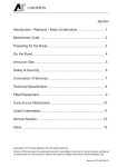
The SnapGear appliance can connect to the Internet using an external dialup analog
modem, an ISDN modem, a permanent analog modem, a cable modem or DSL link as
shown in the following figure:
Figure 3.1 Internet connection
Physically connect modem device
The first step in connecting office network to the Internet is to physically attach your
SnapGear appliance to the modem device. For analog modems, attach the modem serial
cable to one of the SnapGear appliance’s serial ports (i.e. COM1, COM2). For digital
connections (e.g. cable, ISDN, DSL), plug the cable into the Internet port.
Warning
To connect to an ISDN line, the SnapGear appliance requires an intermediate device called a
Terminal Adapter (TA). A TA connects into your ISDN line and has either a serial or
Ethernet interface that is connected to your SnapGear appliance.
Connecting to the Internet
26
Select Internet connection
The next step is to select the method for connecting your SnapGear appliance to the
Internet. From the SnapGear appliance Config Pages, in the Networking menu, select
Connect to Internet and select the method to connect to your local ISP. You can
connect using any a cable, ISDN, DSL or analog modem connection. Selectt he
connection type and click Continue.
Connect to Internet – cable modem
If you are connecting to the Internet using a cable modem, select a cable connection,
select your cable ISP from the list and click Next. If your provider does not appear, select
Generic Cable Modem Provider. For cable modem providers other than Generic, enter
your username and password and click Finish. You are now ready to connect. Click the
Reboot button to save your configuration and reboot your SnapGear appliance.
Connect to Internet – ADSL
If you are connecting to the Internet using ADSL, you must select the connection method
PPPoE, DHCP, or Manually Assign Settings. Alternatively, the SnapGear appliance
can determine the connection method automatically.
Use PPPoE if your ISP uses username and password authentication to access the
Internet. Use DHCP if your ISP does not provide a public IP address and/or instructed
you to obtain an IP automatically from a DHCP Server over the Internet. If your ISP has
given you an IP address, you must manually assign the settings on the
SnapGearSOHO+'s Internet interface. Select the appropriate method and click Apply.
For PPPoE, enter the username and password for your ISP account. By default, your
SnapGear appliance maintains the ADSL connection continuously; however you can
change this if required to Connect on Demand. For on demand connections, enter an
Idle Disconnect Time. This is the time (in minutes) that the SnapGear appliance will wait
before disconnecting if the line is idle.
DHCP connections also require a host name for your SnapGear appliance. Select
Manually Assign Settings and enter the IP Address and Netmask and optionally the
Gateway and the DNS Address if provided by your ISP. Reboot the SnapGear appliance
for the new configuration to take effect.
If you are unsure of the ADSL Connection Method, select Autodetect connection type
and your SnapGear appliance will attempt to automatically determine the connection
method.
Connecting to the Internet
27
Connect to Internet – direct
Choosing Direct Connection to the Internet shows the IP Configuration page. Seethe
section called IP configuration.
Connect to Internet – modem
The following figure shows the Setup modem Internet connection:
Figure 3.2 Setup modem Internet connection
If you are connecting to the Internet using a modem, the system displays the Connect to
Internet via a Modem screen. The following table describes the fields and explains how
to configure the dial up connection to your ISP.
Connecting to the Internet
28
Field
Description
Serial port to dial-out on
Select the SnapGear appliance COM (serial) port you will
use for the modem that will dial your ISP. This port will be
dedicated for the Internet connection; any attempt to dial-in
using this COM port will be blocked.
Note: If a port was previously setup for dial-in and is later
enabled for Internet access, the dial-in function is
automatically disabled.
Name of Internet provider
Enter the name of your ISP.
Phone number to dial
Enter the number to dial to reach your ISP. If you are behind
a PABX that requires you to dial a prefix for an outside line
(e.g. 0 or 9) ensure you enter the appropriate prefix.
ISP DNS Server
Enter the DNS server address supplied by your ISP.
Username and password
Enter the unique username and password allocated by your
ISP. The Password and Confirm Password fields must
match.
Idle timeout
By default, the SnapGear appliance dials-on-demand (i.e.
when there is traffic trying to reach the Internet) and
disconnects if the connection is inactive (i.e. when there is
no traffic to/from the Internet) for 15 minutes. If using dialon-demand, this value can be set from 0 to 99 minutes.
(This option is available in
the Advanced Setup)
Selecting Stay Connected will disable the idle timeout.
Redial setup
(This option is available in
the Advanced Setup)
Statically assigned IP
address
(This option is available in
the Advanced Setup)
Connecting to the Internet
If the dial up connection to the Internet fails, Max
Connection Attempts specifies the number of redial
attempts to make before discontinuing . Time Between
Redials specifies the number of seconds to wait between
redial attempts.
The majority of ISPs dynamically assign an IP address to
your connection when you dial-in. However some ISPs use
pre-assigned static addresses. If your ISP has given you a
static IP address, enter it in Local IP Address and enter the
address of the ISP gateway in Remote IP Address.
29
Internet failover
SnapGear units are designed with the real Internet in mind, which may mean downtime
due to ISP equipment or telecommunications network failure. Failures can occur by
someone removing the wrong plug from the wall, or typing in the wrong ISP password.
Regardless of the reason for this failure, it can potentially be very expensive.
Failover provides the ability to use a low-speed connection when the high-speed
connection fails to allow services to continue operating.
When a main Internet connection fails and a backup connection (or failover) is started,
VPN connections are restarted and dynamic DNS services are advised of the new IP
address. The goal is to make the failover seamless to operation.
Internet failover is currently only available in the SnapGearSOHO+, SnapGearPRO, and
SnapGearPRO+ appliances.
With theSnapGearPRO+, after configuring a normal Internet connection, a link to the
Internet failover page allows you to configure the failover support. You can also access
the failover page by clicking Connect To Internet in the Networking menu.
The following figure shows the advanced configuration option:
Figure 3.3 Advanced configuration option
Connecting to the Internet
30
The following figure shows the failover configuration screen:
Figure 3.4 Failover configuration screen
The following fields can be configured for the failover connection.
Field
Description
IP Address to ping
IP address the SnapGear unit will ping to determine if the
Internet connection is up or down.
Ping Interval
How often to ping the remote machine to determine if the
Internet connection is up or down.
Number of times to attempt
this connection
Number of times to attempt the connection before the
SnapGear unit moves to the failover connection.
Time to wait between retrying connections
If the Internet connection fails immediately when the password
is wrong, or if the SnapGear unit is unable to contact an ADSL
modem to make a connection, specify the amount of time to
wait between retrying this connection after the initial failure is
detected.
Fall forward.
This option is only available
after configuring the failover
connection.
Enable failover.
This option is only available
afterconfiguring the failover
connection.
Connecting to the Internet
This allows the SnapGear unit to continue trying the main
Internet connection until the connection is established. At this
point the SnapGear unit disconnects the backup Internet
connection and continues using the main Internet connection.
Checking this box indicates you want the SnapGear unit to
use the backup Internet connection if the SnapGear unit
detects that the main Internet connection has failed.
31
Failed connection
An Internet connection is considered failed if the SnapGear unit tests the Internet
connection the specified number of times, and fails each time. The SnapGear unit can
test the Internet connection by ensuring that the physical connection was made correctly
(i.e. an IP address was received from the ISP), and then pinging a remote host.
For some Internet connections (e.g. PPPoE ADSL) you may need to ping a remote host
to determine if the Internet connection is up or down. The SnapGear unit will usually
detect if a PPPoE ADSL Internet connection is down.
For Internet connection types that require you to specify a static IP address or use
DHCP, the SnapGear unit cannot usually detect if the Internet connection is down. To
ensure that the Internet connection is up, enter a host for the SnapGear unit to ping.
If the Internet connection fails, the SnapGear unit will attempt to reconnect to the Internet
using the main connection for the number of specified times. After each failed attempt,
the SnapGear unit will wait the number of seconds specified.
For PPPoE and dial-up connections, the SnapGear unit sends an echo request and the
remote machine responds with an echo reply. If more than three echo replies do not
appear, the main connection is considered down.
Warning
You currently cannot failover for an ADSL demand dial-internet connection, or for any type of
modem connection.
Connecting to the Internet
32
Configure PCs to use SnapGear appliance Internet gateway
The PCs on your network must be configured to use the SnapGear appliance as the
default gateway for Internet access. See the section called Configuring the PCs on your
network for more information.
Establishing the connection
If you are connecting to your ISP using a modem or ISDN connection, the SnapGear
appliance will automatically place a call when an application requires access to the
Internet (e.g. sending e-mail, browsing the web, etc).
To establish the connection:
1. From any PC on the network, launch a browser application (e.g. Internet Explorer
or Netscape Navigator).
2. The SnapGear appliance will dial the ISP and log in. On the front panel, the COM
LED will flash when establishing the connection.
3. The ONLINE LED will light when the Internet link is created and your browser will
display the default home page.
4. If Dial-on-demand/Idle time is enabled, the SnapGear appliance will also
disconnect from the Internet when the connection is idle for the specified period.
Internet access is automatic if you are using a permanent connection device (e.g. cable
modem).
Connecting to the Internet
33
4. Dial-in server configuration
SnapGear appliance enables remote and secure access your office network. This
chapter shows how to set up the dial-in features.
Note
The RAS (Remote Access Server) functions n this section are not supported by all SnapGear
appliances.
Your SnapGear appliance can be configured to receive dial-in calls from remote
users/sites. Remote users are individual users (e.g. telecommuters) who connect directly
from their client workstations to dial-into modems connected to the serial ports on the
SnapGear appliance. Remote site dial-in connections can be LAN-to-LAN connections,
where a router at a remote site establishes a dial-in link using a modem connected to the
SnapGear appliance.
The SnapGear appliance dial-in facility establishes a PPP connection to the remote user
or site. Dial-in requests are authenticated by usernames and passwords verified by the
SnapGear appliance.
Once authenticated, remote users and sites are connected and have the same access to
the LAN resources as a local user.
Note
The SnapGear appliance Models SOHO+ and PRO can support up to two dial-in connections.
The SnapGear appliance Models LITE and LITE+ cannot support dial-in connections.
Dial-in server configuration
34
To configure the SnapGear appliance for a dial-in connection:
1. Attach external modems to the relevant SnapGear appliance serial ports. Refer to
Chapter 7, Serial Ports and Modem Devices for modem configuration details.
2. Enable and configure the selected SnapGear appliance COM port for dial-in as
detailed in Dial-in Setup.
3. Set up and configure user dial-in accounts for each person or site requiring dial-in
access.
You can also apply filtering to dial-in connections, as detailed in Chapter 6, Firewall.
Dial-in server configuration
35
Dial-in setup
The following figure shows the dial-in setup:
Figure 4.1 Dial-in setup
To enable and configure Dial-In server for the SnapGear appliance, select Dial-In Setup
from the Networking menu. The following table describes the fields in the Dial-In Setup
screen and explains how to enable and configure dial-in access on a SnapGear
appliance COM port.
Dial-in server configuration
36
Field
Description
Enable Dial-in
To enable and configure dial-in, check the relevant COM port
box. The selected port is now available for dial-in access. If no
COM port is selected, all dial-in attempts will be blocked.
The current dial-in status of all COM ports is displayed. If dialin is already enabled, the checkbox displays a bold or shaded
check mark. If dial-in is not enabled, the checkbox is clear
Note: A port enabled for dial-in cannot be used simultaneously
for dial-out activities (e.g. dial-on-demand Internet
connection). If a port was previously set up for Internet access
and is later enabled for dial-in, the Internet access function is
disabled.
IP Addresses
for Dial-in users
Dial-in users must be assigned local IP addresses to access
the local network. Specify a free IP address from your local
network that each dial-up client will use when connecting to
the SnapGear appliance.
Authentication
Scheme
The authentication scheme is the method the SnapGear
appliance uses to challenge users dialing into the network.
Dial-in clients must be configured to use the selected
authentication scheme which may be one of:
Idle Timeout
•
MSCHAPv2 is the most secure.
•
CHAP is less secure, and PAP (although more
common) is even less secure. If you select None, no
username/password authentication is done on dial-in.
•
RADIUS and TACACS+ use a remote authentication
server on the local network. When selected, you must
enter the IP address of a server setup to use this
scheme.
If a dial-in connection remains inactive, it can be automatically
disconnected after a specified time period. Selecting Enable
idle timeout will disconnect idle connections after 5 minutes.
Idle time can be set between 0 – 99 minutes.
After enabling and configuring the selected SnapGear appliance COM ports to support
dial-in, click Continue and to create and configure the dial-in user accounts.
Dial-in server configuration
37
Dial-in user accounts
User accounts must be set up before remote users can dial-into the SnapGear appliance.
The following figure shows the Dial-in user account creation:
Figure 4.2 Dial-in user account creation
The field options in Add New Account are shown in the following table:
Field
Description
Username
Username for dial-in authentication only. The name is casesensitive (e.g. Jimsmith is different to jimsmith).
Password
Password for the remote dial-in user.
Confirm
Re-enter the password to confirm.
Domain
If your network has a Windows NT server, you can attach a domain
name to your dial-in remote user accounts. This field is optional and
can be left blank.
Dial-in server configuration
38
The following figure shows the user maintenance screen:
Figure 4.3 User maintenance screen
Dial-in server configuration
39
Account list
As new dial-in user accounts are added, they are displayed on the updated Account List.
To modify a password for an existing account, select the account in the Account List and
enter the new password in the New Password and Confirm fields. Click Apply under
the Delete or Change Password for the Selected Account heading, or click Reset if
you make a mistake.
To delete an existing account, select the account in the Account List and check Delete
under the Delete or Change Password for the Selected Account heading. If changes
to the user account are successful, the change is shown on the Dial-in Setup screen . If
the change is unsuccessful, an error is reported as shown in the following figure:
Figure 4.4 Dial-in password error
When you have finished adding and modifying user account details, you can configure
other SnapGear appliance functions by selecting the appropriate item from the Network
or System menus. You can also apply packet filtering to the dial-in service as detailed in
Chapter 6, Firewall.
Warning
If you have enabled a SnapGear appliance COM port for dial-in, this port cannot be used
simultaneously for dial-out activities (e.g. dial-on-demand Internet connection). If a port is
set-up for Internet access, and is later enabled for dial-in, the Internet access function is
automatically disabled.
Dial-in server configuration
40
Remote user configuration
Remote users can dial-in using the SnapGear appliance using the standard Windows
Dial-Up Networking software. Set up a new dial-out connection on the remote PC to dial
the phone number of the modem connected to the SnapGear appliance COM port. After
the dial-in is connected, users can access all network resources as if they were a local
user.
For Windows 95 and Windows 98:
From the Dial-Up Networking folder, double-click Make New Connection and enter the
Connection Name for your new dial-in connection as shown in the following figure:
Figure 4.5 Make new connection screen
Select the modem to use from the Select a device pull down menu.
Click Next and enter the phone number of the modem connected to the SnapGear
appliance.
Click Finish.
Dial-in server configuration
41
An icon is displayed in Dial-Up Networking with your Connection Name. Click the icon
once, and then click File and Properties and click the Server Types tab as shown in the
following figure:
Figure 4.6 Server types
Check the Log on to network and Enable software compression checkboxes. If your
SnapGear appliance dial-in server requires MSCHAP-2 authentication, you also need to
check the Require encrypted password checkbox. Leave all other Advanced Options
unchecked.
Select the TCP/IP network protocols from the Allowed network protocols list.
Warning
Do not select NetBEUI or IPX. If an unsupported protocol is selected, an error message is
returned.
Click TCP/IP Settings and confirm that the Server Assigned IP Address, Server
Assigned Name, Server Address, Use IP Header Compression and Use Default
Gateway on Remote Network are all checked and click OK.
Dial-in server configuration
42
Dial-in and log on to the remote SnapGear appliance by double-clicking the Connection
Name icon. You need to enter the Username and the Password that was set up for the
SnapGear appliance dial-in account as shown in the following figure:
Figure 4.7 Connect to dialogue box
Windows 2000
To configure a remote access connection on a Windows 2000 computer, click Start,
Settings, Network and Dial-up Connections and select Make New Connection.
The network connection wizard will guide you through setting up a remote access
connection:
Figure 4.8 Network connection wizard
Dial-in server configuration
43
Click Next to continue.
Figure 4.9 Connection type
Select Dial-up to private network as the connection type and click Next to continue.
Figure 4.10 Phone number to dial
Tick Use dialing rules to enable you to select a country code and area code. This
feature is useful when using remote access in another state or overseas.
Dial-in server configuration
44
Click Next to continue.
Figure 4.11 Connection availability
Select the option Only for myself to make the connection only available for you. This is a
security feature that will not allow any other users who log onto your machine to use this
remote access connection:
Figure 4.12 Connection name
Enter a name for the connection and click Finish to complete the configuration. By ticking
Add a shortcut to my desktop, an icon for the remote connection will appear on the
desktop.
Dial-in server configuration
45
To launch the new connection, double-click on the new icon on the desktop, and the
remote access login screen will appear as in the next figure. If you did not create a
desktop icon, click Start, Settings, Network and Dial-up Connections and select the
appropriate connection and enter the username and password set up for the SnapGear
appliance dial-in account.
Figure 4.13 Remote access login screen
Dial-in server configuration
46
5. Network configuration
IP configuration
Users can set the IP address configuration for both the LAN and Internet interfaces by
selecting IP Configuration from the Networking menu as shown in the following figure:
Figure 5.1 IP configuration
To configure the LAN Interface of the SnapGear appliance, select either a dynamically or
statically assigned IP address. If the LAN interface of your SnapGear appliance gets its
IP address from a DHCP server on your local network, then check DHCP assigned.
For a static IP address on the LAN interface, enter the IP Address and Netmask in the
fields provided. You must enter a static IP address if the SnapGear appliance will act as
the DHCP server on your local network.
Network configuration
47
If your SnapGear appliance is configured for a Direct Connection to the Internet, you
must also set the IP address for the Internet Interface. Check DHCP assigned if the IP
address of the Internet Interface is set via a DHCP server, or enter the IP Address and
Netmask if you have a static address for the Internet interface.
Enter the IP address of default gateway in the Internet Gateway field. The SnapGear
appliance will send all packets not destined for the local network to this machine.
Enter the IP address of the DNS Server that the SnapGear appliance will use to resolve
domain names in the Domain Name Server field. This is only required if the SnapGear
appliance is configured with a static IP address on the Internet interface and does not
automatically get its DNS server address.
The SnapGear appliance can also be configured to run as a Domain Name Server. The
SnapGear appliance acts as a DNS proxy and passes incoming DNS requests to the
appropriate external DNS server. If this is enabled, all the computers on the LAN should
specify the IP address of the SnapGear appliance as their DNS server.
Network configuration
48
Advanced IP configuration
The following figure shows the advanced IP configuration:
Figure 5.2 Advanced IP configuration
The Hostname is a descriptive name for the SnapGear appliance on the network.
The SnapGear appliance can utilize IP Masquerading where users on the local network
effectively share a single external IP address. Masquerading allows insiders to get out,
without allowing outsiders in. By default, the Internet interface is setup to Masquerade.
Network configuration
49
Masquerading has the following advantages:
•
Added security as only the gateway address is known to machines outside the
local network.
•
All machines on the local network can access the Internet using a single ISP
account.
•
Only one public IP address is used and is shared by all machines on the local
network. Each machine has its own private IP address.
SnapGear recommends setting Masquerade on the Internet interface.
Internet Interface Aliases allows the SnapGear appliance to respond to multiple IP
addresses on the Internet interface. You must also setup appropriate Incoming Access
rules to allow traffic sent to the additional (i.e. aliased) IP addresses to be passed to the
local network.
On rare occasions it may be necessary to change the Ethernet hardware or MAC
Address of your SnapGear appliance. The MAC address is a globally unique address
and is specific to a single SnapGear appliance. It is set by the manufacturer and should
not normally be changed. However, you may need to change it if your ISP has configured
your ADSL or cable modem to only communicate with a device with a known MAC
address.
Network configuration
50
DHCP server
The following figure shows the DHCP server configuration:
Figure 5.3 DHCP server configuration
To help keep your network design as simple as possible, your SnapGear appliance can
act as a DHCP server for machines on your local network. To configure your SnapGear
appliance as a DHCP server, you must set a static IP address and netmask on the LAN
Interface (see the section called IP configuration).
Network configuration
51
Click Configure the server settings on the DHCP Server Configuration screen to:
•
Check the Enable DHCP server checkbox and uncheck the Disable DHCP
server checkbox.
•
Enter the Gateway Address to be distributed to DHCP clients. This is normally
the IP address of the LAN interface of the SnapGear appliance.
•
Enter the DNS Address to be distributed to DHCP clients. Leave this field blank
for automatic DNS server assignment. If your SnapGear appliance is configured
for DNS masquerading, you should either leave this field blank, or enter the IP
address of the LAN interface of the SnapGear appliance.
•
Enter IP address of the WINS server to be distributed to DHCP clients in the
WINS Address field.
•
Enter the Default Lease Time and Maximum Lease Time in seconds. The lease
time is the time that a dynamically assigned IP address is valid.
•
Click Configure the IP addresses to be handed out to enter the addresses from
where the DHCP server will allocate IP addresses to machines on the local
network.
To reserve a particular IP address for a specific machine click Configure the IP
addresses to be reserved for particular hosts. For each reserved IP address, you
must enter the Hostname and MAC Address of the machine as well as the IP Address
that will be allocated to the machine.
To take advantage of the SnapGear appliance’s DHCP server functionality, you should
configure the other machines on your local network to get their IP addresses dynamically
from the SnapGear appliance. Please refer the documentation for the other machines for
instructions on how to configure the local network interface.
Network configuration
52
Advanced networking
Users can perform the following diagnostic tasks on the Advanced Networking screen:
•
Perform a Ping Test.
•
Perform a Trace Route Test.
•
View the Interface Configuration.
•
View the Kernel Route Table.
The advanced networking configuration tasks Traffic Shaping and Additional Routes
are also accessed using the Advanced Networking page.
Traffic shaping
The Traffic Shaping feature of your SnapGear appliance allows you to allocate High,
Medium, or Low priority to the following services: domain (tcp), domain (udp), ftp, ftpdata, http, https, imap, irc, nntp, ntp, pop3, smtp, ssh, and telnet.
Traffic Shaping provides a level of control over the relative performance of various types
of IP traffic. This advanced feature is provided for expert users to fine tune their networks.
Additional routes
The Additional routes feature allows expert users add additional static routes for the
SnapGear appliance. These routes are in addition to those created automatically by the
SnapGear appliance configuration scripts.
Network configuration
53
6. Firewall
The SnapGear appliance has a fully featured, state driven firewall. The firewall allows you
to control both incoming and outgoing access and to detect intrusion attempts, so that
PCs on the office network can have tailored Internet access facilities and be shielded
from malicious attacks.
The SnapGear Firewall filters packets at the network layer, determines whether the
session packets are legitimate and evaluates the contents of packets at the application
layer to provide maximum protection for your private network.
Incoming access
Click Incoming Access on the Firewall menu to show the Incoming Access
configuration page to configure the firewall to:
Firewall
•
Control external access to services provided by the SnapGear appliance itself,
and
•
Control services provided by machines on your local network.
54
Incoming access – administration services
The following figure shows the incoming access configuration page:
Figure 6.1 Incoming access configuration
By default the SnapGear appliance runs a web administration server and a telnet
daemon. Access to these services can be restricted to specific interfaces. For example,
you may want to restrict access to the SnapGear appliance’s configuration web pages
(Web Admin) to machines on your local network. SnapGear does not recommend
disallowing all services, as this will make future configuration changes impossible unless
your SnapGear appliance is reset to the factory default settings.
You can also select the ICMP messages accepted on the Internet interface. Destination
unreachable ICMP messages are always accepted. For example, if you disallow echo
requests, your SnapGear appliance will not respond to pings on its Internet interface.
The SnapGear appliance’s Web Admin pages are usually accessed on the default HTTP
default port (i.e. port 80). Change the port number if you are allowing Internet access to
the web administration page, as this will hide your web administration pages from a
casual web server that finds your SnapGear appliance on the Internet. After changing the
web server port number, you must include the new port number in the URL to access the
pages. For example, if you change the web administration to port number 88, the URL to
access the web administration will be similar to http://192.168.22.1:88.
Firewall
55
External access to services
The following figure shows how to configure external access to services:
Figure 6.2 Configure external access to services
The SnapGear appliance firewall on the Internet interface can be configured to accept or
deny external requests on a specified incoming port, based on the originating (i.e.
source) IP address.
This is useful for restricting external access to the SnapGear appliance's services (e.g.
telnet on port 23) to trusted external IP addresses only. The options specified in the
Administration Services section for disabling web or telnet access on the Internet
interface have lower priority than any rules you specify for web or telnet access in this
section.
Firewall
56
Port forwarding
The following figure shows the port forwarding configuration:
Figure 6.3 Port forwarding configuration
Port forwarding allows the SnapGear appliance to control access to services provided by
machines on your private network from users on the Internet. Requests coming into the
SnapGear appliance on the specified Incoming Port(s) are forwarded to the Target Port
on the Target Server.
Firewall
57
Outgoing access
Your SnapGear appliance can be configured to restrict network traffic going out the
Internet interface. These restrictions can be applied to specific hosts or networks (defined
by IP address), or globally across all hosts on your internal LAN.
Outgoing Access restrictions are applied by denying a group of services (e.g. web and
email) from specific hosts or networks or globally across all hosts.
Your SnapGear appliance’s Outgoing Access Restrictions are configured using security
group classes. Click the security group classes link on the Outgoing Access
Configuration page to set the restrictions for each security group class. Each security
group class can be configured to restrict certain TCP/IP application protocols or to block
specified TCP and UDP ports as shown in the following figure:
Figure 6.4 Security group classes configuration
You can specify the restrictions for each security group class to impose, and apply the
restrictions globally to all machines on your local network or to specific machines or
networks.
Firewall
58
Use the Add Hosts or Networks section to specify the specific machines or networks to
restrict outgoing access as shown in the following figure:
Figure 6.5 Outgoing access settings
Firewall rules
The Firewall Rules configuration page allows firewall experts to view the current firewall
rules and add custom firewall rules.
To access this page, click Rules in the Firewall menu. Only experts on firewalls and
iptables rules will be able to add effective custom firewall rules. Configuring the
SnapGear firewall via the Incoming Access and Outgoing Access configuration pages
is adequate for most applications.
Firewall
59
Intrusion detection and blocking
The following figure shows the Intrusion Detection and Blocking (IDB) configuration:
Figure 6.6 Intrusion detection and blocking configuration
IDB operates by offering a number of services to the outside world that are monitored for
connection attempts. Remote machines attempting to connect to these services generate
a system log entry providing details of the access attempt, and the access attempt is
denied.
Because network scans often occur before an attempt to compromise a host, you can
also deny all access from hosts that have attempted to scan monitored ports. To enable
this facility, select one or both of the block options and these hosts are automatically
blocked once detected.
Firewall
60
The list of monitored network ports can be freely edited. Several shortcut buttons also
provide pre-selected lists of services to monitor. The basic button installs a bare bones
selection of ports to monitor while still providing sufficient coverage to detect many
intruder scans. The standard option extends this coverage by introducing additional
monitored ports for early detection of intruder scans. The strict button installs a
comprehensive selection of ports to monitor and should be sufficient to detect most
scans.
The trigger count specifies the number of times a host is permitted to attempt to connect
to a monitored service before being blocked. This option only takes effect when one of
the previous blocking options is enabled. The trigger count value should be between 0
and 2; with 0 representing an immediate blocking of probing hosts. Larger settings mean
more attempts are permitted before blocking and although allowing the attacker more
latitude, these settings will reduce the number of false positives.
The ignore list contains a list of host IP addresses which the IDB will ignore for detection
and blocking purposes. This list may be freely edited so trusted servers and hosts are not
blocked. The two addresses 0.0.0.0 and 127.0.0.1 cannot be removed from the ignore list
because they represent the IDB host.
Warning
A word of caution regarding automatically blocking UDP requests. Because the source address
of these requests can be easily forged by an attacker, a host that automatically blocks
UDP probes can be tricked into restricting access from legitimate services. Proper firewall
rules and ignored hosts lists will significantly reduce this risk.
Firewall
61
Content filtering
The SnapGear Content Filtering system limits the types of web-based content accessed.
Web-based content featuring profanity, sexually explicit or other objectionable material
can be limited or blocked from the following screens. The following figure shows content
filtering:
Firewall
62
Figure 6.7 Content filtering
Firewall
63
In the Block List, specify text that will block access to any URL containing that text. For
example, if access to websites containing references to “widgets” is a violation, entering
that text will block any URL containing “widgets” including
“http://www.widgets.example.com.”
Warning
This list only refers to the URL; it will not search and block on content.
The Allow List also enables access to URLs containing the specified text.
Filtering levels and reporting
The SnapGear Content Filtering screen allows you to select filtering levels based on
green, yellow, and red color codes. You can select from some commonly blocked content
and set the filtering levels according to your requirements.
Reporting contains the following filtering levels:
Filtering Level
Description
Green (Allowed)
Access to content is allowed. If reporting is active, report the
access.
Yellow (Violation)
Access to content is allowed. If reporting is active, log the access
as a violation of the site policy.
Red (Blocked)
Access to content is blocked. Show the error page to the user. If
reporting is active, log the access as a violation.
An activity report is available by ticking the Enable Reports box.
Warning
The correct time/date must be set on your SnapGear appliance for Reporting to work. The most
effective way to do this is by using a time server.
The filtering and reporting can only be activated after visiting the Registration page.
Firewall
64
7. Virtual Private Networking
Virtual Private Networking (VPN) enables two or more locations to communicate securely
and effectively, usually across a public network (e.g. the Internet) and has the following
key traits:
•
Privacy - no one else can see what you are communicating
•
Authentication - you know who you are communicating with, and
•
Integrity - no one else can tamper with your messages/data.
Using VPN, you can access the office network securely across the Internet using Pointto-Point Tunneling Protocol (PPTP) or IPSec. If you take your portable computer on a
business trip, you can dial a local number to connect to your Internet access provider and
then create a second connection (called a “tunnel”) into your office network across the
Internet and have the same access to your corporate network as if you were connected
directly from your office. Similarly, telecommuters can also set up a VPN tunnel over their
cable modem or DSL links to their local ISP.
With the SnapGear appliance you can establish a secure VPN over the Internet using
either PPTP or IPSec. IPSec provides better security; however PPTP is the preferred
protocol for integrating with existing Microsoft infrastructure. The SnapGear appliance
provides a PPTP server to enable remote Windows clients to securely access your office
network. Using the SnapGear appliance’s PPTP client or IPSec you can also connect
your office network to one or more remote networks.
This chapter explains how to configure the PPTP server and client, as well as IPSec, in
your SnapGear appliance and how to set up remote clients to connect to your VPN tunnel
as shown in the following figure:
Figure 7.1VPN tunneling using PPTP server
Virtual Private Networking
65
PPTP client setup
The SnapGear PPTP client enables the SnapGear appliance to establish a VPN to a
remote network running a PPTP server (usually a Microsoft Windows server).
To set up a SnapGear PPTP VPN Client, select PPTP VPN Client from the VPN menu
and create a new VPN connection by entering:
•
A descriptive name for the VPN connection. This may describe the purpose for
the connection.
•
The remote PPTP server IP address to connect to.
•
A username and password to use when logging in to the remote VPN. You may
need to obtain this information from the system administrator of the remote PPTP
server and,
•
Optionally, the remote network’s netmask.
•
Click Add.
Virtual Private Networking
66
If the remote VPN is already up and running, check Start Now to establish the
connection immediately as shown in the following figure:
Figure 7.2 PPTP client configuration
The SnapGear appliance supports multiple VPN client connections. Additional
connections can be added by following these steps. To set a VPN connection as the
default route for all network traffic, check the Make VPN the Default Route checkbox
and click Apply. This option is only available when the SnapGear appliance is configured
with a single VPN connection only.
After adding a new VPN, two new tables are displayed in the PPTP VPN Client menu.
VPN Connection Status provides information about the State of the VPN (i.e. enabled
or disabled) and the Status of the connection (i.e. up or down).
The VPN Configuration table provides the ability to enable/disable the VPN, edit the
VPN configuration, delete the VPN entry and edit the advanced routing information.
Virtual Private Networking
67
PPTP server setup
The SnapGear appliance includes a PPTP Server, a virtual private network server that
supports up to forty simultaneous VPN tunnels (depending on your SnapGear appliance
model). The SnapGear PPTP Server allows remote Windows clients to securely connect
to the local network.
To setup a VPN connection:
•
Enable and configure the PPTP VPN server.
•
Set up VPN user accounts on the SnapGear appliance and enable the
appropriate authentication security.
•
Configure the VPN clients at the remote sites. The client does not require special
software. The SnapGear PPTP Server supports the standard PPTP client
software included with Windows 95/98, Windows ME, Windows XP, WinNT and
Windows 2000. The VPN connection is simple to configure using the standard
Dial-Up Networking software. The SnapGear PPTP Server is also compatible with
Unix PPTP client software.
•
Connect the remote VPN client.
The following sections provide additional detailed instructions.
Virtual Private Networking
68
Enable and configure the PPTP VPN server
The following figure shows the PPTP server setup:
Figure 7.3 PPTP server setup
To enable and configure your SnapGear appliance’s VPN server, select PPTP VPN
Server from the VPN menu in the SnapGear appliance Config Pages.
Virtual Private Networking
69
The following table describes the fields in the VPN Setup screen and the options
available when enabling and configuring VPN access.
Field
Description
Enable PPTP
Server
Check this box to enable PPTP connections to be established to
your SnapGear appliance.
IP Addresses for
the Tunnel End
Points
Enter the IP addresses for the tunnel end-points. You need to
specify a free IP address on your local network that each VPN
client will use when connecting to the SnapGear appliance.
Please ensure that the IP addresses listed here are not in the
range the DHCP server can assign. Ranges are accepted; for
example 192.168.160.250-254.
Authentication
scheme
PPTP provides an authenticated communication tunnel between
a client and a gateway by using a user ID and password. The
authentication scheme is the method the SnapGear appliance
uses to challenge users wanting to establish a PPTP connection
to the network. The remote client must be set up to use the
selected authentication scheme.
Virtual Private Networking
•
MSCHAPv2 is the most secure. It uses encrypted
passwords. SnapGear recommends the use of
MSCHAPv2 plus data encryption as this keeps your data
private as well as providing secure authentication.
•
CHAP is less secure, and similarly PAP is even less
secure, but more common.
•
RADIUS and TACACS+ make use of a remote
authentication server on the local network. You must
enter the IP address of a server setup to use this
scheme.
70
Configuring user accounts for VPN server
After setting up the VPN server, select Continue and to show the PPTP VPN Server
Accounts screen as shown in the following figure:
Figure 7.4PPTP VPN server accounts screen
Before remote users can set up a VPN tunnel to the SnapGear appliance PPTP server,
they must have a user accounts set up. The field options in the Add New Account are
detailed in the following table.
Field
Description
Username
Username for VPN authentication only. The name selected is casesensitive (e.g. Jimsmith is different to jimsmith). Username can be
the same as, or different to, the name set for dial-in access.
Windows Domain
Most Windows clients expect you to specify a domain name in
upper case. This field is optional.
Password
Enter the password for the remote VPN user.
Confirm
Re-enter the password to confirm.
As new VPN user accounts are added, they are displayed on the updated Account List.
To modify the password of an existing account, Select the account in the Account List
and then enter New Password and Confirm in the Delete or Change Password for the
Selected Account field.
Virtual Private Networking
71
To delete an existing account, Select the account in the Account List and then check
Delete in the Delete or Change Password for the Selected Account field.
If a requested change to a user account is successful, the PPTP VPN Setup screen is
shown with the change noted. An error is displayed if the change request is unsuccessful.
Virtual Private Networking
72
Configuring the remote VPN client
After setting up the SnapGear PPTP VPN server, the remote VPN clients can be
configured to securely access the local network. You need to enter the VPN client
username and password that your remote users will use to access the SnapGear PPTP
VPN from the remote site.
The names may or may not be the same as your normal network username and
password, and should be different from the username and password used by your remote
users use to access their local ISP.
The following figure shows the VPN PPTP IP address:
Figure 7.5 VPN PPTP IP address
Obtain the current IP address of the SnapGear appliance PPTP server. This address
may change if your office network has an external DHCP server (i.e. your ISP
dynamically assigns your an IP address).
Virtual Private Networking
73
To determine the current SnapGear appliance’s PPTP server IP address, select
Diagnostics from the System menu in the main menu bar. The IP address is displayed
in the VPN field. Your remote users must know this PPTP IP address to setup a VPN
tunnel to the SnapGear appliance.
Check that the remote PC has a modem installed and that you have a local ISP account,
(i.e. an ISP phone number and a username and password to log in to the ISP). Although
users are often connected to the Internet using a dial-out modem, VPN connection can
also be set up using a cable modem, ADSL, ISDN or other Internet link.
Ensure that both the VPN and Dial Up Networking (DUN) software is installed on the
remote PC. If necessary, install the Microsoft DUN update (available on the SnapGear
Installation CD) and VPN Client update.
To create a VPN connection across the Internet, you must set up two networking
connections. One connection is for the Internet access provider, and the other connection
is for the VPN tunnel to your office network. Verify that a networking connection is
established for the link to your local ISP.
Set up a new connection for the VPN connection. Your SnapGear appliance’s PPTP
server will operate with the standard Windows PPTP clients in all versions of Windows.
The following sections provide details for client setup in Windows 95/98, Windows NT,
and Windows 2000. Setup instructions for Windows ME and Windows XP can be
deduced from this information and the Microsoft Windows documentation.
Virtual Private Networking
74
Windows 95 and Windows 98
From the Dial-Up Networking folder, double-click Make New Connection. Type
SnapGear appliance or a similar descriptive name for your new VPN connection.
From the Select a device drop-down menu, select the Microsoft VPN Adapter and click
Next. Enter the PPTP IP address of the SnapGear appliance VPN server in the VPN
Server field. This may change if your ISP uses dynamic IP assignment. Click OK and
then click Finish.
Figure 7.6 VPN client setup
Right-click the new icon and select Properties.
Select the Server Types tab and check the Log on to network, Enable software
compression, and Require encrypted password checkboxes. Leave the other
Advanced Options unchecked.
Select the TCP/IP network protocols from the Allowed network protocols list.
Warning
Do not select NetBEUI or IPX. If an unsupported protocol is selected, an error message is
returned.
Virtual Private Networking
75
Click TCP/IP Settings. Confirm that the Server Assigned IP Address, Server
Assigned Name Server Address, Use IP Header Compression and Use Default
Gateway on Remote Network are all selected and click OK.
Figure 7.7 VPN client server settings
Your VPN client is now set up correctly.
Virtual Private Networking
76
Windows NT
From the Dial-Up Networking dialog, click New and select the Basic tab.
In the Entry name field, enter SnapGear appliance or a similar descriptive name and
click Next.
Enter the SnapGear appliance’s PPTP IP address into the Phone Number field.
Warning
Note that this IP address may change if your ISP uses dynamic IP assignment.
In the Dial Using dialog box, select RASSPPTPM (VPN1) and click Next.
Click More and select Edit entry then Modem properties from the menu.
Select the Server tab.
Select TCP/IP only.
Warning
Do not select NetBEUI or IPX. If an unsupported protocol is selected, an error message is
returned.
Select the Security tab and select Accept only Microsoft encrypted authentication.
Click OK.
Your VPN client is now set up correctly.
Virtual Private Networking
77
Windows 2000
To set up VPN access, first setup a Dial Up Networking account to access the Internet.
Once you have done this, you are ready to begin.
The first thing you need to do is log in as Administrator on your PC. After logging in, from
the Start menu, select Settings and then Network and Dial-up Connections as shown
in the following figure:
Figure 7.8 Network and dial-up connections
To set up your VPN account, double-click Make New Connection and then click Next to
show the Network Connection Type window:
Figure 7.9 Network connection type
Select Connect to a private network through the Internet and click Next.
Virtual Private Networking
78
This displays the Destination Address window:
Figure 7.10 Destination address
Enter the SnapGear PPTP server’s IP address and click Next. Select the Connection
Availability you require on the next window and click Next to display the final window:
Figure 7.11 Completing the network connection wizard
Enter an appropriate name for your connection and click Finish.
Your VPN client is now set up correctly.
Virtual Private Networking
79
Connecting the remote VPN client
Firstly, connect to the Internet using the network connection to your ISP.
After authenticating the connection to your ISP, select the connection for the SnapGear
appliance VPN.
For Windows 95/98/2000, enter the username and password allocated by your SnapGear
appliance’s VPN administrator and click Connect.
For Windows NT, click Dial and enter the username and password allocated by your
SnapGear appliance’s VPN administrator.
After you are authenticated to the network, you can check your e-mail, use the office
printer, access shared files and browse the network as if you were physically on the LAN.
To disconnect the VPN tunnel connection to the remote SnapGear appliance:
•
On the desktop, double-click My Computer then Dial-Up Networking and select
the phonebook entry for the SnapGear appliance VPN.
•
For Windows 95/98/2000, click the Disconnect button
•
For Windows NT, click the Hang up button
You can then disconnect from the Internet.
Virtual Private Networking
80
IPSec setup
The SnapGear appliance supports IPSec tunnels as well as PPTP tunnels. To setup your
VPN using IPSec, select IPSec from the VPN menu to display the following screen:
Figure 7.12 IPSec setup
Enable IPSec by clicking the Enable IPSec box underneath the IPSec Setup title and
then click Submit.
Enable the interface where you want to use IPSec. This may be the default gateway or a
PPP interface for ADSL and cable modems, or eth1 if the SnapGear appliance is
connected to a router before connecting to the Internet and then click Submit.
Virtual Private Networking
81
To add a new IPSec connection click on Add under Add New IPSec Connection to
show the following screen:
Figure 7.13 Add new IPSec connection
Enter a descriptive name for the connection in the Connection Name field.
Virtual Private Networking
82
Choosing to connect with Aggressive Mode increases interoperability with third party
IPSec servers that only support aggressive mode connections.
Enter the local gateway settings. Internal subnet/netmask is the private network behind
the SnapGear appliance. External IP is the public-network interface that the SnapGear
appliance will use for IPSec.
The Authentication Identifier is required when using RSA key signatures for multiple
Road Warriors and is used to identify the other participant during authentication. If this
field is blank, the Authentication Identifier defaults to the External IP.
Nexthop refers to the next-hop gateway IP address to the public network this field is not
normally required and can be left blank. This option is only available if you have chosen a
specific route; SnapGear recommends that you use the default route. Enter the remote
gateway settings. To connect to/from a remote machine that does not have a fixed IP
address (e.g. a Road Warrior), enter an External IP of 0.0.0.0 only.
Dead Peer Detection allows the tunnel to be restarted if the remote gateway stops
responding. This option is only used if the remote gateway supports Dead Peer
Detection. It operates by sending notifications and waiting for acknowledgements. Delay
is the time between notifications. The tunnel will be restarted if no acknowledgements
have been received for a period of Timeout.
The recommended keying used in IPSec is Automatic Keying (IKE). The default and
recommended method of authentication is using a Pre-Shared secret that should be at
least 24 characters long. This should be a phrase that you can remember easily but is
difficult for others to guess. You can also authenticate using RSA digital signatures.
Virtual Private Networking
83
Click Add to complete the IKE setup as shown in the following screen:
Figure 7.14 Automatic keying setup
Virtual Private Networking
84
Click Submit to add the new IPSec tunnel after selecting the appropriate Automatic
Startup, Authorization, Authentication, and Key Configuration.
Warning
The pre-shared secret must be entered identically at each end of the tunnel. The IPSec tunnel
will fail to connect if the pre-shared secret is not identical at both ends.
The pre-shared secret is a highly sensitive piece of information. It is essential to keep this
information secret. Communications over the IPSec tunnel may be compromised if this
information is divulged.
Aggressive mode phase 1 settings
IPSec combines a number of cryptographic techniques:
Technique
Description
Block ciphers
A symmetric cipher that operates on fixed-size blocks of plaintext, giving
a block of ciphertext for each.
Hash functions
A complex operation that uses both a hashing algorithm (MD5 or SHA)
and a key.
Diffie-Hellman
The Diffie-Hellman key agreement protocol allows two parties (A and B)
to agree on a key in such a way that an eavesdropper who intercepts the
entire conversation cannot learn the key. The protocol is based on the
discrete logarithm problem and is considered to be secure.
Automatic keying provides a mechanism for regularly changing the cryptographic keys
used by the IPSec tunnel. This regular key change results in enhanced security; if a third
party gets one key, only the messages between the previous re-keying and the next are
exposed.
Key Lifetime is the time between consecutive re-keying events (i.e. the lifetime of a key).
Shorter values offer higher security at the expense of the computational overhead
required to calculate the new keys. SnapGear recommends a default value of 1 hour.
Virtual Private Networking
85
Checking the Enable Perfect Forward Secrecy of keys checkbox means that an
attacker who acquires the SnapGear appliance’s long-term key (i.e. the pre-shared secret
or RSA Signature Key Private Section) cannot:
•
Read previous messages which they may have archived, or
•
Read future messages without performing additional successful attacks
Perfect forward secrecy of keys provides the maximum security and is the recommended
setting.
IPSec interoperability
Please see the Support Knowledge Base
(http://www.SnapGear.com/knowledgebase.html) on the SnapGear Web Site
(http://www.SnapGear.com/) for detailed information on successfully establishing IPSec
tunnels between your SnapGear appliance and other vendors’ equipment.
Virtual Private Networking
86
8. System
Time server
The SnapGear appliance can synchronize its system time with a remote time server
using the Network Time Protocol (NTP). Configuring the NTP time server ensures that
the SnapGear appliance's clock (in UTC) will be accurate soon after the Internet
connection is established. If NTP is not used, the system clock will be set randomly when
the SnapGear appliance starts up.
To set the system time using NTP, select the Set Time checkbox on the NTP Server
Configuration page and enter the IP address of the time server in the Remote NTP
Server field.
Password
The SnapGear appliance’s password is used to restrict access to the SnapGear
appliance’s configuration web pages (WebAdmin) and the SnapGear appliance itself.
The SnapGear appliance password is the ‘key’ to the security of your network and must
be kept secret. SnapGear recommends choosing a password that is easy for you to
remember but hard for unauthorized people to guess.
A potential security issue may be introduced by having a network-connected SnapGear
appliance accessible, using the factory default password. To prevent this, the password
for the SnapGear appliance should be changed when Setup Wizard is run or the
Configuration web pages are accessed for the first time.
The SnapGear appliance password can be changed at any time using the configuration
web pages by clicking Password in the System menu.
Note
The username field is ignored as there is no username.
The SnapGear appliance factory default password is default.
System
87
Diagnostics
If you are experiencing problems with your SnapGear appliance, diagnostic information is
provided on the SnapGear appliance’s Configuration web pages.
To access this information, from the System menu, click Diagnostics. Advanced
network diagnostics can be viewed by selecting the Networking menu, then Advanced
Networking.
Advanced
The options on the Advanced page are intended for network administrators and
advanced users only.
Warning
Altering the advanced configuration settings may render your SnapGear appliance inoperable.
The System Log contains debugging information that may be useful in determining
whether all SnapGear appliance’s services are operating correctly.
The SnapGear appliance also provides the option of re-directing log output to a remote
machine using the syslog protocol. This is enabled by selecting Enable Remote
Logging, entering the IP address of the remote machine and clicking Apply.
System
88
Flash upgrade
The SnapGear appliance firmware can be updated with newer versions available from
the SnapGear web site (http://www.SnapGear.com/downloads.html). The firmware is in
binary image files (.bin) that can be transferred from a PC on the local network directly
into the SnapGear appliance’s flash memory. To perform flash upgrades, the SnapGear
appliance must be configured on the local network with an IP address.
Flash upgrades can be performed using the configuration web pages. To do this, click
Advanced then Flash Upgrade and enter the IP address of the PC with the binary
image and the appropriate filename. A TFTP server must be running on the machine
hosting the file.
During the upgrade, the front panel LEDs on the SnapGear appliance will flash in an inand-out pattern. The SnapGear appliance retains its configuration information with the
new firmware.
Warning:
If the flash upgrade is interrupted (e.g. power down), the SnapGear appliance will stop
functioning and will be unusable until its flash is reprogrammed at the factory. User care is
advised.
RESET button
The simplest method to clear the SnapGear appliance’s stored configuration information
is by pushing the reset button on the back of the SnapGear appliance box. The reset
button is the small hole between the serial ports and Ethernet ports. A bent paper clip is
the simplest method.
Pushing the reset button clears all stored configuration information, reverts all settings to
the factory defaults, and reboots the SnapGear appliance.
System
89
9. Technical support
The System menu contains an option detailing support information for your SnapGear
appliance.
This page provides basic troubleshooting tips, contact details for SnapGear Support, and
links to the SnapGear Knowledge Base as shown in the following figure:
Figure 9.1 Technical support
The Technical Support Report page is an invaluable resource for the SnapGear
Technical Support Staff to analyze problems with your SnapGear appliance. The
information on this page gives the Support Staff important information about any
problems you may be experiencing.
If you experience a fault with your SnapGear appliance, please attach the Technical
Support Report to your support request.
9. Technical support
90
Appendix A – LED status patterns
The following table shows the different LED illumination combinations that can indicate
possible error conditions.
In each case, the LEDs indicated will be on and steady, unless otherwise noted, and all
other LEDs will be off. The Power and System LEDs are not part of the LEDs indicating
status. Where the action indicates that you should contact your dealer, please note the
LED pattern to assist with faster response and recovery action.
LED Pattern
Status
Action
VPN
Memory failure.
Please contact your
dealer.
COM2
Console device cannot initialize.
Please contact your
dealer.
All LEDs on
In recovery mode, usually from a bad Flash
image. While the reset button is held in this
will be the LED pattern.
VPN &and Internet Link
Cannot load static data into memory,
probably memory and/or Flash problem.
Please contact your
dealer.
COM2 and Internet Link
Cannot load SBSS, probably memory
and/or Flash problem.
Please contact your
dealer.
Online
Memory exception.
Please contact your
dealer.
Appendix A – LED status patterns
91