1
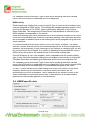
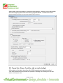
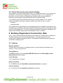
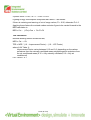
Building Regulations Part L2 (2006) & Part F VE-SBEM User Guide <Virtual Environment> 6.0 Page 1 of 35 Contents 1. Introduction ................................................................................................................ 3 1.1. 1.2. 1.3. 1.4. 2. Guidance on performing Part L2 (2006) assessments............................................ 8 2.1. 2.2. 2.3. 2.4. 2.5. 3. Room Data in the context of Part L2 (2006) ...................................................................................25 Room Data General tab (actual building) .......................................................................................26 Room Data Building Regs tab (actual building) ..............................................................................26 SBEM specific data .........................................................................................................................28 Room Data Room Condition tab (actual building) ..........................................................................29 Room Data System tab (actual building) ........................................................................................30 Building Regulations Construction Data ............................................................... 30 6.1. 6.2. 6.3. 6.4. 7. General ...........................................................................................................................................23 Building Details ...............................................................................................................................23 Thermal Bridging.............................................................................................................................24 EPC: EPC Recommendations ........................................................................................................24 Room Data (actual building).................................................................................... 25 5.1. 5.2. 5.3. 5.4. 5.5. 5.6. 6. Building settings ..............................................................................................................................22 Calculations.....................................................................................................................................23 Tools ...............................................................................................................................................23 L2 (2006) Building & System data........................................................................... 23 4.1. 4.2. 4.3. 4.4. 5. Fundamentals of Part L2 2006..........................................................................................................8 Organisation of Part L2 2006 compliance analysis in the <VE>.......................................................9 Real, actual and notional buildings .................................................................................................11 Steps in performing a <VE> Compliance analysis..........................................................................13 Tips for Passing Part L2a................................................................................................................20 Part L2 (2006) VE-SBEM – Analysis........................................................................ 22 3.1. 3.2. 3.3. 4. What is VE-SBEM? ...........................................................................................................................3 Overview of Part L2 (2006) VE-SBEM..............................................................................................4 Methods and Requirements..............................................................................................................5 Overview of VE-SBEM interface features.........................................................................................6 Glazing ............................................................................................................................................30 Doors...............................................................................................................................................31 Ground floors ..................................................................................................................................31 All construction categories ..............................................................................................................31 Part L2 (2006) VE-SBEM Results ............................................................................ 31 7.1. 7.2. SBEM method .................................................................................................................................31 SBEM-EPC method ........................................................................................................................33 Page 2 of 35 1. Introduction 1.1. What is VE-SBEM? VE-SBEM is a facility within the Virtual Environment’s <VE> Compliance view providing facilities for either testing compliance with various Building Regulations, or generating energy performance certificates (EPCs) for the same Regulations. An alternative route to compliance is offered with the ApacheSim facility; refer to the Part L2 (2006) ApacheSim User Guide for further detail. Part L2 (2006) Regulation applies to new buildings other than dwellings in England and Wales for which construction did not start before 6th April 2006. Part F Regulation applies to new buildings other than dwellings in Northern Ireland for which construction did not start before 6th April 2006. Part L (2002) applies to buildings in England, Wales and Northern Ireland for which construction started before 6th April 2006. If construction had not started before that date, the 2006 edition of Part L2, or Part F, applies. VE-SBEM analysis is not available for Part L (2002). Virtual Environment Thermal category <VE> Compliance view Part L2 (2006) Part F Data for the VE-SBEM analysis is taken from the <Virtual Environment> model, supplemented where necessary by inputs specific to the requirements of the selected Regulation. This data is used to produce an input file for the BRE tool SBEM v3.0. The <Virtual Environment> launches the BRE SBEM tool with the input data file and the BRE SBEM tool performs a compliance assessment, or generates an EPC. Results of the VE-SBEM analysis are presented as follows 1. Compliance document (PDF file) plus Calculation Summary (one page of graphs as a PDF file) and Calculation Details (more detailed breakdown as a HTML file) or 2. Energy Performance Certificate (PDF) and Recommendations Report (PDF). XML files are also generated for lodgement in official databases. Page 3 of 35 1.2. Overview of Part L2 (2006) VE-SBEM The requirements of The Building Regulations, Part L2 (2006 edition) as applied to new buildings are set out in Approved Document L2A[1]. This document should be consulted in the course of any submission for Part L2 compliance. The function and scope of the approved documents is set out in the ‘Use of guidance’ section: “Approved Documents are intended to provide guidance for some of the more common building situations. However, there may well be alternative ways of achieving compliance with the requirements. Thus there is no obligation to adopt any particular solution contained in an Approved Document if you prefer to meet the relevant requirement in some other way.” The broad requirements of L2 are set out in the Requirement section of Approved Document L2A[1] (referred to in this document as ‘L2A’). They cover: Reasonable provision shall be made for the conservation of fuel and power in buildings by: a. limiting heat gains and losses through i) thermal elements and other parts of the building fabric and ii) pipes, ducts and vessels used for space heating, space cooling and hot water services. b. providing and commissioning energy efficient fixed building services with effective controls; and c. providing the owner sufficient information about the building, the fixed building services and their maintenance requirements so that the building can be operated in such a manner as to use no more fuel and power than is reasonable in the circumstances. The detailed requirements are outlined in Section 0: General guidance, under the heading Demonstrating Compliance. Five criteria must be satisfied (paragraph numbers refer to L2A): Criterion 1: the calculated CO2 emission rate of the building as constructed (the building emission rate, BER) must not be greater than the target rate (the target emission rate, TER) which is determined by following the procedures set out in paragraphs 18 to 23. Criterion 2: the performance of the building fabric and the heating, hot water and fixed lighting systems should be no worse than the design limits set out in paragraphs 33 to 62… Criterion 3: Those parts of the building that are not provided with comfort cooling systems have appropriate passive control measures to limit solar gains. Criterion 4: the performance of the building, as built, is consistent with the prediction made in the BER… Criterion 5: The necessary provisions for enabling energy efficient operation of the building are put in place… L2A should be consulted for details of special considerations and exemptions applying to particular classes of buildings. Page 4 of 35 Some of the requirements of Part L2 cannot be tested in software (Criteria 4 and 5 fall into this category). However, IES aims to provide software covering all requirements that can be so tested. 1.3. Methods and Requirements By contrast to L2 (2002), the 2006 regulations offer only one compliance route. This has some similarity with the Carbon Emissions Calculation Method in the 2002 regulations, though there are important differences. The 2006 regulations have no counterpart of the L2 (2002) Elemental or Whole-building methods. Within the single compliance route for L2 (2006) a choice is permitted regarding the analysis tool used to calculate the BER and TER. The carbon dioxide emission calculations that form the basis of these performance indicators can be calculated using either The Simplified Building Energy Model (SBEM) developed by BRE, or Approved commercial software The L2 (2006) VE-SBEM software falls into the second category. The requirements tested by the software are Criteria 1 & 2 & 3, which are implemented in the software as follows: Criterion 1: Achieving an acceptable building CO2 emission rate (BER) The BER and TER values are obtained from the simulated carbon dioxide emissions of two buildings. The ‘actual building’, which forms the basis of the BER calculation, is the building as designed, but subject to standard operating conditions dictating levels and patterns of occupancy, internal gain and minimum ventilation. The ‘notional building’, which forms the basis of the TER calculation, is a version of the actual building modified in accordance with rules relating to glazing area, insulation and system efficiency. These rules are related to the standards laid down for the 2002 Elemental Method. The notional building is also subject to the standard operating conditions. The notional building is created within the BRE SBEM tool. Both buildings have monthly heat balances performed for standard weather data appropriate to the building location. Results are automatically fed into the BRUKL compliance calculator provided by BRE. The standard operating conditions are functions of the building type and the activities occurring within each room. They are laid down in the National Calculation Methodology (NCM)[3]. It is important to note that the stipulation of standard operating conditions for L2 (2006) compliance calculations means that results as calculated for L2 (2006) will in general be different from those calculated for the ‘real’ building (for example in Apache View or for the L2 (2002) Carbon Emissions Calculation Method). Page 5 of 35 To obtain the TER, the CO2 emissions for the notional building are modified by certain factors as set out in the General Guidance section L2A under the heading Regulations. Details are set out in L2A.The purpose of these factors is to tighten the requirement on the actual building so that its performance exceeds that of the notional building. By this means the 2006 regulations impose a measurable degree of improvement over the standards applied in the 2002 regulations. Criterion 2: Limits on design flexibility Criterion 2 imposes constraints on U-values and other aspects of building and system performance. Maximum and mean U-values for different classes of construction must not exceed stated values. The software applies checks for compliance with this requirement before performing the actual and notional building calculations. Conditions are also laid down in the following areas (see L2A section headed Design limits for building services): Controls Energy metering Heating and hot water service systems Cooling plant Air handling plant Insulation of pipes, ducts and vessels Lighting Criterion 3: Passive control measures to limit overheating Criterion 3 requires all spaces in the building without air-conditioning to have a low risk of overheating (see SBEM Technical Manual for a definition of this). SBEM v3.0 is the first version of SBEM which assesses the building against this criterion. 1.4. Overview of VE-SBEM interface features The <VE> Compliance view offers the following Methods, which may be selected using the Method selector on the <VE> Compliance toolbar: ApacheSim ApacheSim – EPC SBEM SBEM - EPC This Guide covers the last two methods above, in conjunction with selecting either Part L2 (2006) or Part F from the Regulatory Framework selector on the toolbar. The Regulatory Frameworks all share core features of the <VE> Compliance view, such as the model workspace, the browsers, the menus and the toolbars. For a description of these please consult the <VE> Compliance View User Guide. Page 6 of 35 Actual and notional buildings For the ApacheSim Method a selector labelled ‘Current model’ appears at the righthand side of the <VE> Compliance toolbar. This allows you to switch between displaying the actual building and the notional building. For both SBEM methods this selector disappears, as the notional building is generated internally by the BRE SBEM tool, and is only visible to the user in the form of output files. In most respects the actual building is the same as the ‘real’ building used in other <VE> views and Regulatory Frameworks. However, there are differences in the Room Data, where for L2 (2006) certain attributes assigned to the ‘real’ building are overridden by attributes representing the standard internal conditions stipulated for L2 (2006) in the NCM methodology. The notional building differs from the actual building in the following respects, in accordance with the rules set out in the NCM document: Glazing (and in some cases door) areas are adjusted. Standard constructions are applied. Where there are unheated buffer spaces (including unheated roofs) in the actual building, the notional building treats these as heat loss paths for adjacent heated rooms (following the principles laid down in BS EN ISO 13789:1999[2]). For these adjacencies standard constructions are applied, replacing the heat loss paths (including the unheated spaces) in the actual building. Standard Apache Systems are assigned to rooms depending on the type of conditioning assigned to the rooms in the actual building. The notional building is created automatically from the actual building in the BRE SBEM tool and cannot be modified. Building regulations room data Data relating to individual rooms is entered via the Room Data tabs. General Building Regulations data, such as the room ‘activity’, is specified on the Building Regulations tab. SBEM specific data, including all Lighting data is also entered on this tab. The internal gain data for the room’s Building type and Activity is read by SBEM from its own copy of the NCM database, so Room Data’s Internal gain and Air exchange tabs are not visible (as they would be for the ApacheSim method). Building regulations construction data Building regulations data relating to constructions (for instance, whether a window is classified as display glazing) is entered via fields labelled ‘Building Regulations’ within the construction data dialogues in APcdb. Part L analysis and results The Part L analysis and results dialogue on the lower edge of the <VE> Compliance view is divided into two parts: Page 7 of 35 “<Regulation Framework name>- Analysis”: facilities for specifying the Part L analysis to be performed “Results”: facilities for viewing the results of the analysis There is also a button for the VE-SBEM version of Building and System data. 2. Guidance on performing Part L2 (2006) assessments The <VE Compliance> View provides the means to test compliance with the conservation of fuel and power requirements of the UK building regulations, including the 2006 regulations applying in England, Wales and Scotland. This User Guide covers Part L2, the section of the regulations covering non-domestic buildings in England and Wales. The following guidance is aimed at providing an overview of the implementation of the regulations in the <VE> software. 2.1. Fundamentals of Part L2 2006 New Part L2 regulations came into force on May 6th 2006 and apply to non-domestic buildings beginning construction after this date. The regulations requiring designers to demonstrate significant reductions in carbon emissions from building energy use relative to the standards set by the previous (2002) edition of the regulations. This is achieved by performing a detailed analysis of the carbon emissions of two buildings: The actual building – the building as designed, but subject to standard patterns of occupancy and plant operation, and The notional building – a version of the building that conforms to standards similar to those applying in the Part L2 (2002) Elemental Method. The notional building is subject to the same occupancy and plant operation patterns as the actual building. The analysis must demonstrate that the actual building’s carbon emissions improve on those of the notional building by a specified margin – 28% for an air conditioned building. It is this improvement that constitutes the tightening of the regulations in the 2006 edition. The analysis of carbon emissions must be performed with accredited software applying the National Calculation Methodology (NCM), such as <VE> Compliance or BRE’s iSBEM program. By contrast with the 2002 regulations, where a choice of three compliance routes was offered, the 2006 regulations stipulate a single compliance procedure. This has much in common with the Carbon Emissions Calculation Method (CECM) of the 2002 regulations, but there are important differences including the following: The actual building’s performance must not merely match, but significantly improve on that of the notional building. Page 8 of 35 Assessments must be performed under standard occupancy and plant operating conditions. This means that under the new regulations, some of the data entered by the user to model the building for design work has to be replaced by different data for the purpose of compliance analysis. Requirements on the control of summertime solar gains apply to the actual, not the notional building, and only to rooms without mechanical cooling. In this respect the 2006 notional building sets a slightly less demanding performance target than the 2002 notional building. In terms of analysis methodology, the most significant change with respect to the 2002 Carbon Emissions Calculation Method is the requirement for standard occupancy and plant operating conditions. The consequence of this is that, in addition to the actual and notional buildings, the designer will usually need to model and analyse (for design and other non-regulations purposes) a third building: The real building – this is the building as designed, and with the occupancy and plant operation conditions expected to apply in reality, rather than the standard conditions stipulated for Part L2 compliance. The real building is the building presented in Apache View, where the special conditions required for Part L2 (2006) do not apply. The testing of carbon emissions constitutes Criterion 1 of Part L2. The full set of criteria is as follows: Criterion 1 – Achieving an acceptable building CO2 emission rate (BER). Criterion 2 – Limits on design flexibility: this sets minimum standards for building fabric and system performance. Criterion 3 – Limiting the effects of solar gains in summer: this imposes limitations on solar gains and temperatures in those parts of the building that are not provided with comfort cooling systems Criterion 4 – Quality of construction and commissioning: this lays down requirements that the building must meet after construction. (Not covered by <VE> Compliance.). Criterion 5 – Providing information: certain information must be provided to the owners of the building. (Not covered by <VE> Compliance.). Users of the <VE> Compliance software are strongly advised to study the official documents defining the regulations. 2.2. Organisation of Part L2 2006 compliance analysis in the <VE> In the IES <Virtual Environment> all building regulations compliance testing is performed in the <VE> Compliance View. This covers the 2002 and 2006 regulations for England and Wales as applied to both dwellings and non-dwellings, together with their counterparts in Scotland. Page 9 of 35 The starting point for a compliance analysis, however, is the input of geometrical data in ModelIT. The Template Manager, a central resource available from all Views, is typically used next to set up room system and ventilation parameters. Apache View, while not essential for compliance testing, commonly plays a part in the input of Part L data that is shared by other Apache View application, and Views such as SunCast and MacroFlo may also be invoked. The purpose of this section is to provide an overview of the roles played by the different parts of the <VE> in the compliance testing process. ModelIT handles the input of the building geometry. The Template Manager provides facilities for setting room conditions for a range of thermal applications. In the context of Part L2, it also allows the specification of room activities that define the standard occupancy and plant operation conditions that apply in Part L2 (2006). In Part L2 compliance tests these standard conditions automatically override certain of the Room Data settings that would otherwise be taken from the Room Template. Apache View covers thermal applications such as heating and cooling loads calculation, and calculation outside the context of Part L. The analysis in this View applies to the real building, for which all the input data is under your control. Where data is shared between the real building and the actual building, this data may be entered in either Apache View or <VE> Compliance. Examples of such shared data include: Constructions Infiltration But for VE-SBEM the following can only be entered in <VE> Compliance: Location HVAC systems Renewables (in this case SBEM modelling is simpler than ApacheSim’s) <VE> Compliance covers thermal analysis specific to the Building Regulations. Some of the data required by the Building Regulations is shared with Apache View, as indicated above, and may be entered or edited in either View. Other regulationsspecific data must be entered in the <VE> Compliance view. This includes: Regulatory framework – eg Part L2 (2006) (assumed in the list that follows) Building type Room activities (may be specified by means of templates) Data relating to lighting energy savings Heat bridging data Stage of analysis (Design or As Built) Data required by the BRUKL compliance calculator, including addresses, system characteristics and air-tightness properties <VE> Compliance displays data for the actual building by default. The notional building may also be inspected in this View. Page 10 of 35 2.3. Real, actual and notional buildings The definition, creation and purpose of these three buildings can be summarized as follows. The real building is the building that you see in Apache View. It is the building as designed, and with the occupancy and plant operation conditions expected to apply in reality, rather than the standard conditions stipulated for Part L2 compliance. In Apache View it forms the basis for the analysis of heating and cooling loads and simulations. The actual building is the building as designed, but subject to standard patterns of occupancy and plant operation for Part L2 (2006), as defined in NCM. The actual building is the building displayed by default in <VE> Compliance. It is identical to the real building in all respects except occupancy (including associated internal gains and minimum ventilation rates) and plant operation conditions, which are given standard settings in <VE> Compliance as a function of the attributes ‘building type’ and ‘room activity’. Aspects of the actual building that are shared with the real building may be edited either Apache View or <VE> Compliance. The notional building is a version of the actual building that is modified to conform to a clearly defined set of standards relating to glazing area, constructions and system characteristics. Its purpose is to provide a benchmark or target against which to measure the performance of the actual building. The notional building is subject to the same occupancy and plant operation patterns as the actual building. Unlike L2 (2006) ApacheSim the notional building for VE-SBEM cannot be viewed in <VE> Compliance as it is created internally by the BRE SBEM tool. The real building Users interested in compliance testing only will not need to consider the real building as an entity distinct from the actual building. They can thus bypass Apache View. They should, however, be aware that certain room template attributes are overridden in <VE> Compliance. Aside from this point, which is covered in more detail below, the real building does not need to be considered further in the context of <VE> Compliance. The actual and notional buildings, however, can usefully be described in more detail. The actual building The actual building allows you control over the following aspects of the design, which it shares with the real building: Data shared between actual building and real building: Location Geometry (including orientation and glazing) Constructions System characteristics including renewables Infiltration rates (permeability) Page 11 of 35 The actual building differs from the real building in terms of its occupancy and plant operation, which for the purpose of Part L2 (2006) are forced to standard patterns linked to the activity associated with each room. The data in this category is Activity (NCM Template) Room Data: Occupancy Equipment gains Lighting levels (expressed in terms of illuminance) Room conditioning (heating and cooling set points and operation periods) Minimum ventilation rates For the purpose of Part L2 (2006) compliance analysis, this data is outside your control and cannot be edited. Note that these attributes are present in the Room Template for use in Apache View analyses, but the settings appearing there are overridden in the Part L analysis. The standard settings for <VE> Compliance are brought into the room by means of a second template called the NCM Template which is applied in combination with the usual Room Template. The NCM Template contains the standard operating conditions (as listed above) associated with the room’s NCM activity. For example, a room assigned the activity ‘Open plan office’ in a building of type ‘Office’ has an NCM Template called ‘NCM Office: Open plan office’. This contains the occupancy and equipment gains, the lighting level and profile, the room conditioning settings and the minimum ventilation regime laid down as standard for NCM assessments of an open plan office. NCM Templates appear in the list of Room Templates in the Template Manager, where they can be examined in detail. The activity (sometimes called the NCM activity) is assigned to the room on the Room Data Building Regulations tab, and may optionally be specified by means of the corresponding attribute in the Room Template. The activity, which is always associated with a particular building type, exists solely for the purpose of building regulations and is only used by <VE> Compliance. Setting the room activity automatically assigns the correct NCM Template and all the data associated with it. The name of the NCM template, together with that of the room template, can be seen displayed on the General tab of the Room Data dialogue. Not all the Room Data is set by the NCM Template. Just as in Apache View, each room in <VE> Compliance has a Room Template, and this sets the parts of the Room Data that are not covered by the standard activity settings – namely User-supplied Room Data: System characteristics Measures to improve the efficiency of lighting systems Infiltration rates The Room Data displayed and used in <VE> Compliance is thus drawn partly from the NCM Template and partly from the Room Template, as follows. The data on the Room Conditions tab is drawn entirely from the NCM Template. These parameters, which include set points and operation times for heating and cooling plant and hot water demand, are fixed for Part L2 by the room activity, and override the corresponding settings in the room template. Page 12 of 35 The data on the System tab is drawn entirely from the room template. The system parameters are under your control, and may be adjusted as part of the process for achieving compliance. By applying these rules, <VE> Compliance automatically sets the attributes that are laid down by the room’s NCM Activity, while giving you control over those aspects where good design can produce energy and carbon savings – namely system performance, infiltration (air-tightness) and ventilation strategies involving the use of outside air for cooling. To this list can be added improvements to the building fabric, and to system characteristics, which of course do not feature in the room template data. It should be added that wherever the room template is mentioned above, there is (as usual) the option to override the template settings manually in individual rooms or groups of rooms. However, NCM template settings cannot be overridden in this way, except in the special case of lighting gains. System characteristics for the actual building (which it shares with the real building) are set by means of Apache Systems. A suitable set of systems should be created and assigned to groups of rooms. The ‘UK NCM system data wizard’ facilitates this process and allows the system characteristics to be specified using an iSBEM-like interface. 2.4. Steps in performing a <VE> Compliance analysis The following workflow is recommended for preparing and performing a <VE> Compliance analysis for Part L2 (2006). The plan need not be followed slavishly. Variations can be made in the ordering of the tasks and experienced users may wish to take alternative approaches to some of the stages. The purpose of the plan is to guide you through the basic process. (Extra data required by the SBEM-EPC method is not described in this section.) Step 1. Create geometry The process usually begins with the entry of building geometry in ModelIT. Step 2. Set location and weather data The building location is specified in the SBEMlocate utility. The L2 regulations currently specify 11 locations in England and Wales, but the use of any of Edinburgh, Glasgow or Belfast is also permitted if local circumstances make this appropriate. On the other hand, Part F *requires* the weather location to be Belfast. Unlike the ApacheSim route, it is not necessary for a VE-SBEM user to purchase the TRY and DSY weather files from CIBSE as SBEM holds this data internally. Page 13 of 35 Step 3. Create and assign constructions Constructions for building elements such as walls, roofs and glazing are created in the Constructions Database (CDB) utility accessible via Apache View or <VE> Compliance. They should satisfy the U value requirements of Criterion 2. The construction definition should include allowance for non-repeating thermal bridging, using an area-based thermal bridging coefficient. Constructions may be assigned to building elements in either Apache View or <VE> Compliance. Note that VE-SBEM assumes the ground floor U values entered in CDB have already been corrected in accordance with EN ISO 13370. This also means the floor area/perimeter method of calculating the ground floor should not be used, because it does not incorporate this correction. (This is different from iSBEM, which does allow uncorrected U values, with SBEM applying the correction internally). Step 4. Set building type and general data At this stage you may wish to go to <VE> Compliance and set up some of the highlevel data required for the compliance analysis. First check that the Regulatory framework selector is set to ‘Part L2 (2006) – ApacheSim’. In the ‘Building settings’ box near the bottom of the screen select a building type from the list. This indicates the type of building for Part L2 purposes and determines what room activities can be specified in the building. It also automatically sets the Building Category, which determines glazing areas in the notional building. For a building with multiple use, the various parts can be analysed by including NCM activities from other NCM building types. This is a new feature in version 5.6. Not all zones may need to be included in a compliance run for example separate buildings may exist within the same model. The part(s) of the building included in a particular analysis is defined by the settings of the check boxes ‘Include room in Building Regs analysis?’ for each room on the Room Data Building Regulations tab. Step 5. Create or import room templates An efficient way to assign Room Data is by means of Room Templates. A Room Template contains a collection of settings that define the internal conditions applying in a room of a given kind. By defining these conditions centrally you can assign them quickly to large numbers of rooms and transfer them readily to other models via the Import Template mechanism. Room Templates contain data arranged on tabs under the headings Building Regulations, Room Conditions, Systems, Internal Gains and Air Exchanges. Not all this data is used in <VE> Compliance assessments, some being overridden by standard settings. It is therefore important to understand where and how the various components of Room Template data are used. In particular, if you do not intend to use the analysis options available in Apache View (which analyses the real building) you do not need to set Room Template data on the Room Conditions and Internal Gains tabs, or create air exchanges of the Auxiliary Ventilation type. Page 14 of 35 One of the attributes that can usefully be set in the Room Template is the NCM Activity, which is always partnered with an NCM Building Type. If these attributes are set in the Room Template, rooms assigned the template will automatically have the NCM Activity (and all the Room Data associated with it) set in <VE> Compliance. If you adopt a policy of including NCM Activity settings in your Room Templates you will save a lot of time and effort assigning NCM Activities to individual rooms and groups of rooms in <VE> Compliance. The next section provides guidance on the Room Template settings. Step 6. Room Template and Room Data settings for L2 (2006) assessments When creating Room Templates it is important to understand which Room Template settings will be used in <VE> Compliance and which are overridden by standard activity-based settings. Building Regulations (taken from Room Template or specified room by room) This tab contains data used exclusively by <VE> Compliance. Some of the fields can be set in the Room Template. Others appear only in the <VE> Compliance Room Data and must be set on a room-by-room basis. The check box ‘Include room in Building Regs analysis?’ allows you to restrict the Part L analysis to part of the building only. The ‘Type of room’ attribute is normally set to ‘Heated room’, but the following alternative settings are provided to cover various types of unheated space: Unheated roof – use this type for an unheated roof space lying outside the insulated building envelope (ie where the insulation is at ceiling level). Glazing cavity (required only rarely) – use this type for a glazing cavity that has been modelled as a separate room for calculation purposes. Unheated buffer space – use this type for other types of unheated space attached to the building but lying outside the insulated building envelope. Examples are car parks and lean-to outbuildings. Internal void or warm roof – use this type for floor and ceiling voids, and for roof spaces that lie inside the insulated building envelope (ie with insulation at rafter level). In the case of the first three types listed above – all representing types of unheated buffer space – an external ventilation rate must also be entered for the purpose of calculating U values for Criterion 2. All the above types of room are excluded from the floor area summation upon which the emission ratings are based. The settings NCM Building type and NCM Activity together specify the activity assigned to the room for the compliance analysis, which in turn (via the NCM Template) sets the standard conditions applied for occupancy and plant operation. While these attributes are optional in the Room Template, it is a good idea to set them there to save effort in <VE> Compliance. Page 15 of 35 The building regulations tab has specific SBEM information; reference should be made to the BRE iSBEM user manual for description of terms. Within this section the air permeability, zone ventilation (supply & extract), destratification fans and SBEM lighting data can be defined. Room conditions (taken entirely from NCM template) The data set on this tab in the Room Template will be ignored in <VE> Compliance (but it will be used for assessments of the real building in Apache View). In <VE> Compliance, the data on this tab can be viewed but not edited. It is taken from the NCM Template as part of the specification of standard occupancy and plant operation conditions. System (taken from Room Template) The data set on this tab in the Room Template will be used in both <VE> Compliance and Apache View. In either of these views, data on this tab is initially taken entirely from the Room Template (but as usual you have the option to override this data in individual rooms). For compliance assessments, the important parameters on the System tab are the following. In the Systems box: HVAC system – this indicates the Apache System serving the room’s space conditioning needs DHW system – this indicates the Apache System serving the room’s hot water needs including any solar energy system In the System outside air supply box: Free cooling flow capacity – this indicates the maximum intake of outside air that is available for free cooling. In the case of a naturally ventilated room, a value of 5 ach would be typical to model ventilation by window opening. In the case of an air conditioned room, where the outside air is brought in via the system, it would be usual to express the value in l/(s·m2) and a value of 0.5 in l/(s·m2) would be typical. Note that this figure represents the additional outside air intake over and above the minimum ventilation level. Free cooling is covered further in the User Guide. Parameters on the System tab that can be ignored are: Auxiliary ventilation system – this is not applicable because under the NCM conventions there is no conditioning of ventilation air. Sizeable parameters (shown in blue) – sizing plays no part in <VE> Compliance. Humidity limits – these are disabled for <VE> Compliance assessments in line with the conventions applying in the NCM systems approach. Flow rate and profile for System outside air supply – in <VE> Compliance this type of air supply is replaced by standard ventilation patterns handled by Auxiliary Ventilation air exchanges. Page 16 of 35 The setting of data on the System tab is closely linked with the setting of data in Apache Systems, which is dealt with below. Internal gains (taken from NCM Template – lighting editing permitted) The lighting data for VE-SBEM is defined via a button on the Building regulations tab. Air exchanges (auxiliary vent from NCM Template, other vent from Room Template) Air exchanges are covered by the SBEM data on the Building regulations tab. Step 7. Create and assign HVAC and DHW Systems It is recommended that HVAC and DHW systems characteristics for <VE> Compliance analysis are specified within the framework of Apache Systems. Apache Systems provide a robust and uncomplicated system model that has been harmonised with that provided in iSBEM with the aim of providing a point of reference and common ground between these alternative compliance methods. Systems are one of the aspects of building design where substantial carbon emissions improvements can be introduced. The system data is therefore under your control, and it is shared between the real building (as displayed in Apache View) and the actual building (as displayed in <VE> Compliance). The Apache System HVAC model has three key parameters, which can be defined in summary as follows: SCoP – the efficiency of the heating system SSEER – the efficiency of the cooling system (if present) Auxiliary Energy Value – energy required for fans, pumps and controls These are the most important parameters featuring in the calculation of the energy consumed by the space heating and cooling systems. Taken together with the fuels specified for heating and cooling, they encapsulate most of the important data about system performance in relation to carbon emissions. On the Apache System dialogue there are other parameters that are linked with the heating and cooling system efficiencies and do not represent independently editable settings. For example, the heating system’s Generator seasonal efficiency and Heating delivery efficiency are linked to the SCoP by the relation SCoP = (Generator seasonal efficiency) × (Heating delivery efficiency) so that in terms of carbon emissions they can be viewed as secondary to the SCoP. On the cooling side an analogous relationship exists between SSEER and the following parameters: EER – the cooling system generator energy efficiency ratio or COP CDE – the cooling delivery efficiency, and HRP – the heat rejection pump and fan power fraction namely SSEER = EER * CDE / (1 + (EER + 1)*HRP) In terms of carbon emissions EER, CDE and HRP can thus be viewed as secondary to the SSEER. Page 17 of 35 These ‘secondary’ parameters are important for certain design tasks in Apache View – for example the calculation of boiler and chiller loads. But for <VE> Compliance, SCoP and SSEER are the key efficiency measures. Auxiliary energy value is a concept that has been developed in connection with the NCM methodology. This parameter indicates the power consumption of fans, pumps and controls associated with the space heating and cooling systems. It is expressed in terms of Watts per square metre of floor area served, and is incurred when the heating and cooling systems are running. Parameter values can be entered directly into the Apache System dialogue. But it will usually be appropriate to make use of the UK NCM System Data Wizard to assist this task. The UK NCM System Data Wizard has been based on the analogous facility in iSBEM. Its purpose is to guide you through the process of describing the system properties and to generate values for the three key parameters. In addition to the key parameters mentioned so far, there are other system parameters of importance such as heating and cooling system fuels and ventilation heat recovery effectiveness. These are also generated automatically from data entered in the wizard. More information on using the wizard is provided in the <VE> Compliance User Guide. New nomenclature for heating, cooling efficiencies has recently been introduced that aligns <VE Compliance> with the NCM. Definitions of these can be found in the DCLG document ‘Non-Domestic Heating, Cooling and Ventilation Compliance Guide’. This is freely downloadable from the DCLG website: http://www.odpm.gov.uk/index.asp?id=1130726 SCoP and SEER values for commonly available plant can be found at: www.eurovent-certification.com The DHW system wizard enables the definition of the delivery efficiency, storage and the secondary circulation efficiencies and pumping power. The DHW heating demand can be derived from a solar water heating system. This system will use solar power, when available, to pre-heat the water for the DHW system. A storage system can be defined for the solar water heating system. Note that Apache Systems may be imported from other projects on the back of Room Templates, allowing system data to be transferred between projects. Step 8. Define renewable systems Four renewable systems are available for use within the actual building; CHP, Wind, PVs and Solar water heating. CHP should be sized to provide the base load of heating for the building and the power generated will be used to offset the electrical energy usage in the building. Wind and PVs will, when the prevailing weather conditions permit, provide electrical energy that will offset electrical energy usage in the building. Page 18 of 35 Step 9. Set or check fuel carbon emission factors The carbon emission factors to be used in L2 (2006) compliance assessments are stipulated in the NCM methodology for a range of fuels. The Fuels Data facility in Apache View and <VE> Compliance allows fuel carbon emission factors to be edited. The default values are those which conform with NCM. For compliance runs, any departure from these values, or use of fuels not on the NCM list, would need to be carefully justified in supporting documentation. Step 10. Set Building & System Data We now return to the Building & System Data dialogue to prepare for the compliance calculations. For VE-SBEM, Building & System Data is distributed over three tabs. First, on the General tab, fill in the address and contact details. Then move to the Building & System Performance tab. This contains data required by the BRUKL compliance checker that collates the calculation results and generates the compliance report. Building air permeability at 50 Pa – this is not yet available in VE-SBEM. Location Description – optional Project Complexity – Level 3, 4 or 5 Related party disclosure – optional Stage of analysis – As built or As designed The remaining parameters appear in the box labelled ‘Adjustment for management features’. These settings allow credit to be taken in the BER calculation for management features applied to electrical power and lighting: Electric power factor Lighting systems have provision for metering? Lighting systems metering warns of ‘out-of-range’ values? The final tab deals with Thermal Bridging which SBEM applies to all junctions. If nothing is changed on this tab the default psi values shown will be used. To obtain non-accredited defaults for any or all of the non-metal clad junction types, uncheck the box(es) on the right before clicking the “Restore defaults” button. Step 11. Perform compliance run When you are satisfied that the actual building model is defined as intended, click on the button ‘CO2 Emissions: Part L compliance’. The progress of the SBEM calculation is indicated on the screen. Results from both buildings, together with data provided on the Building & System Data dialogue, is then fed into the BRUKL compliance calculator. The calculations performed there to produce the Building CO2 Emission Rate (BER) and Target CO2 Emission Rate (TER) are set out in Appendix B When the process is complete a summary of the result of the Part L2 analysis will be displayed on the Results tab, and you can click on a button to display the compliance document generated by BRUKL. Any failures are shown in red text in the document. Page 19 of 35 Step 12. Review, revise and repeat as necessary If the result is a pass for all of Criterions 1 – 3 you may move on to the next stage. Otherwise you will need to improve the design and try again. Step 13. Collate and submit results Assuming a successful outcome, the Part L2 (2006) compliance process is now complete in relation to those aspects that can be tested before construction. The reports generated, together with appropriate supporting evidence, can now be submitted to Building Control. The content of Part L submissions should be agreed in advance with the local Building Control officer as there may be differing interpretations during the early stages of implementation of the new regulations. These are likely to be resolved over time as a sufficient number of Competent Persons are trained and accredited. It may be necessary, for instance, to agree how compliance with Criterion 4 will be met post construction as part of the pre-Construction report. 2.5. Tips for Passing Part L2a The following measures should be considered when attempting to achieve a pass for the Building CO2 Emission Rate (Criterion 1). Many of them will also benefit summer temperatures (Criterion 3). They are listed in rough order of importance. Systems Substantial reductions in building emission rate can be achieved by improving HVAC efficiency. The UK NCM System Data Wizard provides options for changing a range of system settings and parameters. For systems that are not covered there, it is permissible to enter appropriate parameters in the Apache System dialogue, provided they can be justified on the basis of manufacturers’ data. Fuel choice has a major effect on carbon emissions. Specific fan power (SFP) is a parameter that has a significant effect on system performance. The Non-Domestic Heating, Cooling and Ventilation Compliance Guide defines requirements for a number of features including SFP. These are potentially onerous requirements that need to be taken into account from the start of projects. Designers need to be careful to allow large enough plant and riser space to ensure that these requirements can be met. Note that default values for SFP in the UK NCM System Data Wizard (which mirror those in iSBEM) tend to be somewhat high, often exceeding the Criterion 2 requirement. These therefore need to be edited. The ‘System adjustment’ and ‘Control corrections’ options in the wizard produce worthwhile improvements in performance. DHW systems should be examined for efficiency opportunities. Page 20 of 35 Lighting Efficient lighting and lighting controls offer substantial potential for bringing down emission rates and moderating summer temperatures. Any saving in lighting consumption has a double benefit, directly reducing electrical load and by reducing room gains having a favourable effect on summertime cooling loads and temperatures. Glazing Reducing glazing area, introducing shading and optimising glazing type may all improve the building’s performance. The implications for natural lighting, should, however be borne in mind. Ventilation Since infiltration is reduced to low levels by Criterion 2, and minimum ventilation levels are laid down by the room activities, the main opportunity for using ventilation control to reduce carbon emissions and summer temperatures is free cooling. DHW demand (changing areas) The NCM templates for DHW usage have been found to be high for some activities, particularly changing areas in sports centres and schools. The DHW usage can be changed by altering the designation of activity areas, but this would need to be agreed in advance with Building Control. Adjustments for management features The settings entered in this box on the Building & System Data ‘Building & System Performance’ tab produce useful reductions in the Building Emission Rate (BER). Constructions Improving U-values will tend to reduce heating, but may increase cooling demand in air-conditioned buildings. Increasing the solar performance of the glass by reducing the solar gains into the building can reduce cooling requirement, but may also increase heating demand. To assess which option (U-value or solar performance) will have the greatest effect, perform a test run on the actual building and look for the dominant load. Buildings with high internal gains and large areas of glazing will almost certainly be cooling dominated. Increasing the thermal mass of the building, for example using exposed ceiling slabs, will tend to reduce cooling demand and moderate summer temperatures. Page 21 of 35 Infiltration The air permeability of the building envelope has to conform to the standard set by Criterion 2, namely a permeability of 10 m3/hr/m2 at 50 Pa (corresponding to an air leakage index of 15 m3/hr/m2). Guidance in CIBSE TM23 indicates that this permeability typically gives rise to an air infiltration rate of about 0.25 ach. An improved permeability can be assumed to produce an improved infiltration rate in proportion. Note that while reducing infiltration rates will tend to lower heating energy, it may increase cooling energy by reducing the building’s ability to dispose of internal heat gains. 3. Part L2 (2006) VE-SBEM – Analysis This dialogue, on a tab at the lower edge of the <VE> Compliance screen, deals with general data required for Part L2 (2006) VE-SBEM compliance analysis. It also provides the means to execute compliance calculations. Results from the compliance calculations are displayed on the neighbouring Results tab. The Analysis and Results tab will be visible provided no room is selected. Both SBEM and SBEM-EPC methods are covered in this section, with differences for the EPC method highlighted in italics. 3.1. Building settings This frame handles the input of general data required for Part L (2006) VE-SBEM calculations. Building type The building type for the L2 (2006) compliance analysis, sometimes referred to as the NCM building type. The NCM methodology requires the building to be assigned a type such as ‘Airport terminal’, ‘Hospital’ or ‘Office’. For each building type there is a set of ‘activities’ that can be assigned to rooms in the building (optionally via templates) and which dictate the conditions assumed in those rooms. The building type also determines the building category, which is used to set the glazing percentages in the notional building. Building Category For each building type a Building Category is automatically set. This determines glazing in the notional building. Set Building & System Data This button displays the Building & System Data dialogue, which is also accessible via the Settings menu. Page 22 of 35 3.2. Calculations Only the “CO2 Emissions” button is available for VE-SBEM. EPC: a single “Generate EPC” button appears. 3.3. Tools This frame provides shortcuts to tools for setting the following model data: Site location and weather data (SBEMlocate) Constructions Building Templates Apache Systems 4. L2 (2006) Building & System data This pop-up dialogue, which may be accessed either via the Building Settings button ‘Set Building & System Data’ or via the Settings menu, allows you to enter general data relating to the building and its systems required by the SBEM calculation. Both SBEM and SBEM-EPC methods are covered in this section, with differences for the EPC method highlighted in italics following EPC:. 4.1. General These entries provide data for the BRUKL compliance document. Please avoid unusual characters. Any commas entered will be automatically changed to spaces. Building: name, street address (EPC: 3 lines), city, postcode Building occupier: name, telephone, street address, city, postcode Certifier: name, telephone, street address, city, postcode. EPC: Assessor number, Accreditation scheme, Qualifications, Trading name, Trading address, Insurance company, Policy number, Effective date, Expiry date, PI Limit 4.2. Building Details Location Description Project Complexity Related party disclosure Stage of Analysis “As built” or “As designed”. (EPC: fixed at “As built”) Page 23 of 35 Adjustment for management features These settings allow credit to be taken in the BER calculation for management features applied to electrical power and lighting. Electric power factor Lighting systems have provision for metering? Lighting systems metering warns of ‘out-of-range’ values? EPC: EPC This section has additional EPC data – the first two (UPRN, Date) *must* be filled in correctly, because the unique Certificate number will be generated from them. UPRN Inspection Date Does the building have special conservation status? Welsh language EPC required? District Heating District heating can be taken into account for. Enter a carbon dioxide conversion factor, if this is known. Otherwise, use the default value. 4.3. Thermal Bridging Restore defaults 4.4. EPC: EPC Recommendations The available NCM recommendations are listed by Category which can be selected from the left hand list. Another way of selecting NCM recommendations is through the Code selector at the top. NCM recommendations cannot be deleted. The user may modify NCM recommendation data (except the Text) and then three things occur: The recommendation changes from green to blue in the list The bottom frame shows “(EDITED)” The “Revert to NCM” button becomes enabled. “Revert to NCM” will discard the user’s changes and reverse the above three actions. The user may add new recommendation(s) in the current Category using either the Add or Copy buttons. These appear blue from the beginning and can be deleted. The user may exclude any recommendations (green or blue) from consideration by SBEM, by double clicking the tickbox in the list. These then change from green or blue to grey. Double clicking the cross back to a tick will include them again and return to the original colour. Page 24 of 35 In the Recommendations Report, the recommendations will appear as follows: Section (a) Green NCM recommendations triggered by SBEM and with a payback of less than 3 years, listed in increasing order of payback Section (b) Green NCM recommendations triggered by SBEM and with a payback of 3 to 7 years, listed in increasing order of payback Section (c) Green NCM recommendations triggered by SBEM and with a payback of over 7 years, listed in increasing order of payback Section (d) Blue NCM recommendations triggered by SBEM *and* all blue USER recommendations (no trigger for these), listed in increasing order of payback Grey NCM recommendations will not appear at all, even if SBEM would have triggered them. Grey USER recommendations will not appear at all. Note: at SBEM v3.0 some information in the VE interface does not appear in the Recommendations Report, as follows. Assessor comment Energy impact CO2 saved per £ spent Applicable to a specified HVAC/DHW System (The Payback does not appear directly but does define the layout and order of the Report as described above). 5. Room Data (actual building) 5.1. Room Data in the context of Part L2 (2006) Each room has a set of attributes that describe conditions within it. This data, known as Room Data, provides input to the thermal analysis programs. In the VE-SBEM Compliance view, Room Data is divided into four categories: General – Room name and ID, Templates, floor area and volume data Building Regs – room attributes for Building Regulations compliance checks Room Conditions – heating and cooling set points and room thermal modelling settings System – parameters describing the system serving the room For most thermal applications, a single set of Room Data applies to each room. However, for Part L (2006) the picture is complicated by two factors: 1. Special room conditions are stipulated for Part L2 (2006) compliance analyses. 2. There is a notional building which has room conditions that differ in some respects from those in the actual building. Page 25 of 35 This section deals with the conditions in the actual building. Here, certain room conditions are taken from data entered by the user (these are often specified by means of a Room Template), and others are dictated by the conditions laid down in the NCM methodology for the particular building type and activity applying to the room (in the main these are taken from an ‘NCM template’). Each tab of the Room Data dialog must be considered separately to gain a full understanding of the way the NCM rules are applied. The basic content of the Room Data tabs, and the procedures for editing it, are described in the <VE> Compliance and Apache User Guides, as these features are common to all thermal applications and Regulatory Frameworks. The exceptions and special rules applying to Room Data in Part L2 (2006) are described below. 5.2. Room Data General tab (actual building) With one exception, data displayed on this tab is the same for all thermal applications. The exception is the NCM Template, which is displayed only for Part L 2006. NCM Template The template automatically assigned to the room as a function of its ‘activity’ (see Building Regs tab) to specify those aspects of Room Data that are dictated by the NCM methodology for use in L2 (2006) compliance calculations. 5.3. Room Data Building Regs tab (actual building) The content of this tab varies with the Regulatory Framework, so is covered in its entirety here rather than in the <VE> Compliance User Guide. Include room in Building Regs analysis? Tick this box to include the room in the building regulations analysis. By switching off rooms using this box you can perform separate analyses on different parts of the model. Calculations in <VE> Compliance will include only the rooms that have this box ticked. If an included room is adjacent to an excluded room, or a room in an inactive layer, the adjacency is treated as a ‘reflexive boundary condition’, which means that conditions in the adjacent, non-included, room will be assumed to be the same as in the included room. Type of room This setting determines how the room will be treated for Part L2 (2006). The options are as follows: Heated space – the usual designation, applying to all occupied spaces within the insulated building envelope (whether they are directly served by heating plant or not). Spaces of this type must be assigned an NCM activity, and will be treated as heated for the purpose of the Part L analysis. Page 26 of 35 Unheated roof – assign this type to a ‘cold’ roof space that has insulation at its base (ie at ceiling level). Rooms assigned this type will not be explicitly modelled in the notional building but incorporated in the elements linking the unheated space with adjacent conditioned spaces. Glazing cavity – windows, rooflights & doors connecting heated rooms with this space will be treated as external. This type is included to cover cases where a glazing cavity is treated for modelling purposes as a separate space. Unheated buffer space – this room type applies to spaces such as car parks, unheated stairwells and other spaces that form a buffer between the conditioned areas of the building and the outside. This type should only be assigned to spaces lying outside the insulated building envelope. Rooms assigned this type will not be explicitly modelled in the notional building but incorporated in the elements linking the unheated space with adjacent conditioned spaces. Internal void or warm roof – this room type applies to ceiling and floor voids, and to ‘warm’ roofs – those with insulation at rafter level. This type should be applied to unheated, unoccupied spaces that lie within the insulated building envelope. Note: Where a space is subdivided for calculation purposes into separate levels connected by holes there are 3 possible approaches to the assignment of ‘Type of room’: a) Combine all the levels into one space. b) Assign the upper levels the same type of room and activity as the occupied space at floor level. They will then be heated and ventilated like that space, but will not receive gains because their floor area will be zero. c) Assign the upper levels the type ‘Internal void or warm roof’, so that they will be unheated. A drawback with option c) is that in the notional building air exchange between the levels will not be modelled so there will be unrealistic thermal barriers between them. Options a) and b) are therefore preferred. External ventilation rate (air changes per hour) This parameter applies only to rooms of type unheated roof space, unheated buffer space and glazing cavity. It is used for the calculation of effective U-values through the space from adjacent heated spaces using BS EN ISO 13789:1999[7]. These Uvalues are used in the Part L2 Criterion 2 checks. Template NCM building type An efficient way to set NCM activities for rooms is to set the activity in the Room Template. The activity will then be automatically set, along with other Room Template attributes, for all rooms to which the template is assigned. If the selected room has an NCM activity set in its Room Template, the building type associated with that activity is displayed here, provided that it matches the building type set for the model in Building Settings. In other instances, the Template NCM building type box displays the text ‘Unset or incompatible’. Page 27 of 35 For unheated rooms (those with Type of room set to anything other than Heated room), the NCM activity is undefined and is not displayed. NCM activity Each heated room (defined as a room for which Type of room is set to Heated room) must be assigned an NCM activity. This defines the standard operation pattern of the room for the purpose of L2 (2006), which is defined by attributes on the various Room Data tabs. The assignment of these Room Data attributes is effected by the NCM template corresponding to the activity. Each NCM building type has a predefined list of NCM activities available to its rooms. Once the model building type is defined in Building Settings, the associated activities will be available to heated rooms in the building and can be assigned using the NCM activity attribute. It is recommended that the NCM activity is set in the Room Template. This saves work as it means that the activity will be automatically set for all rooms assigned that template. An NCM activity is only meaningful in the context of a building type, so this, too, must be set in the template. If no activity is specified in the template the room’s NCM activity will revert to the default activity for the model building type. If the NCM activity is set in the template, and is compatible with the model building type, it may (like other template settings) be overridden in the room by un-ticking the Template check box and selecting an alternative activity from the drop-down list. For unheated rooms (those with Type of room set to anything other than Heated room), the NCM activity is undefined and is not displayed. In this case a special NCM template called ‘NCM unheated space’ is automatically assigned to the room. In Part L2 (2006) certain Room Data settings are under your control (via the room template, which may be overridden in individual rooms) and others are set automatically by the NCM template. This is explained in the context of each of the Room Data tabs in the sections which follow. A brief account of the data used to populate the various tabs appears on the tab title bar. 5.4. SBEM specific data Page 28 of 35 SBEM data for air permeability, ventilation and lighting is entered via the SBEM data and SBEM lighting data within the building regulations tab. This data follows the requirements laid down in the BRE iSBEM user manual. 5.5. Room Data Room Condition tab (actual building) All the data on this tab is taken from the NCM template and cannot be edited. This data specifies the set points and profiles for heating and cooling and the hot water consumption rate. Page 29 of 35 5.6. Room Data System tab (actual building) All the data on this tab is under your control. It is shared with other <VE> views such as Apache View and other Regulatory Frameworks within <VE> Compliance. In particular, the room should be assigned an Apache System with properties accurately describing the system proposed for the actual building. The following System tab attributes that would normally appear in the ‘System outside air supply’ frame are, however, hidden from view in Part L2 (2006): Flow rate Variation profile The reason is that a specification of scheduled minimum ventilation forms part of the standard room conditions associated with the NCM activity (which is handled via data on the Air Exchange tab). To avoid a double specification of minimum ventilation the System tab ventilation parameters are disabled in Part L2 (2006). 6. Building Regulations Construction Data Part L (2006) requires certain attributes to be entered for constructions in addition to the data required for other thermal calculations. This data is entered in the constructions database program APcdb. The additional attributes (broken down by construction category) are: 6.1. Glazing Display window? Tick this box if the window is a display window. Such windows are exempt from certain L2 (2006) requirements. Transmittances VE-SBEM requires only the g-value (BS EN 410) and the Visible light normal transmittance (bottom right). Local shading This is ignored by VE-SBEM. External shading For VE-SBEM only the Sky diffuse transmission factor is required. Internal shading For VE-SBEM only the Shading coefficient is required. Page 30 of 35 6.2. Doors Door type Select from the following types: a) personnel door b) vehicle access or similar large door c) wall or roof element that is not to be treated as a door for the purposes of Part L d) smoke vent (Note: VE-SBEM treats this as a personnel door) e) high usage entrance doors Doors of types b, d and e form special categories in Part L. Type c is provided to allow door drawing facilities in ModelIT to be used to create wall or roof elements. 6.3. Ground floors Do not use the floor area / perimeter method to auto-calculate U values for VE-SBEM because this does not correct the value in line with EN ISO 13370. 6.4. All construction categories Thermal bridging coefficient This is not used by VE-SBEM. The psi values for different junction types (metal clad and non-metal clad) in Building Settings are used instead. Note however that the Metal Cladding setting in CDB will be used by VE-SBEM to determine which of the two possible psi values applies. 7. Part L2 (2006) VE-SBEM Results This tab on the dialogue at the lower edge of the <VE> Compliance screen allows you to view the results of Part L2 (2006) calculations. Because the results are very different, SBEM and SBEM-EPC methods are discussed separately. 7.1. SBEM method Building Emissions Rate (BER) The Building Emissions Rate (kgCO2/m2) calculated for the actual building. Notional Building Emissions Rate The Building Emissions Rate (kgCO2/m2) calculated for the notional building (Cnotional). Page 31 of 35 Target Emissions Rate (TER) The target building emissions rate, derived from the Notional Building Emissions Rate (Cnotional) by applying the Improvement Factor and LZC Factor using the formula: TER = Cnotional × (1 – improvement factor) × (1 – LZC) Improvement Factor A preset factor determining the degree to which the TER must improve on the Notional Building Emissions Rate (Cnotional). LZC Factor The Low and Zero Carbon benchmark, which together with the Improvement Factor determines the degree to which the TER must improve on the Notional Building Emissions Rate (Cnotional). Did the analysis pass the CO2 emissions rating? The pass/fail result for Criterion 1. ‘YES’ if BER<TER, ‘NO’ otherwise. View Compliance Doc Click on this button to view the Compliance Document generated by BRUKL using inputs from the SBEM calculations, together with the data entered in Building & System Data and the results of the Criterion 2 and Criterion 3 checks. Calculation details Click on this button to view the calculation data using inputs from the SBEM calculations, together with the data entered in Building & System Data and the results of the Criterion 2 U-value checks. Extra output files Two further output files are copied to the project’s Regs\SBEM\BRUKL folder and may be of interest. Both are in comma-separated format. <buildingname>_not_sim.csv The calculation details for the Notional building <buildingname>_dr.csv The data reflection report for the Actual building Page 32 of 35 7.2. SBEM-EPC method Part L TER The target building emissions rate, derived from the Notional Building Emissions Rate (Cnotional) by applying the Improvement Factor and LZC Factor using the formula: TER = Cnotional × (1 – improvement factor) × (1 – LZC) Typical The Building Emissions Rate (kgCO2/m2) calculated for the typical building. Standard The Building Emissions Rate (kgCO2/m2) calculated for the reference building, adjusted by a fixed improvement factor of 0.235 as follows: Cstandard = Creference x (1 – 0.235) Actual BER The Building Emissions Rate (kgCO2/m2) calculated for the actual building. Asset Rating, Band The ratio of the Actual emission to the Standard emission, where 50 corresponds to a 1:1 ratio: EPC Rating = (Cactual / Cstandard ) × 50 The band letter and colour corresponding to this (as also shown on the EPC) is shown under the Actual emission figure. The Part L and Typical bands are also shown, based on similar formulae (the numerical rating values are shown on the EPC). Part LRating = (CTER / Cstandard ) × 50 Typical Rating = (Ctypical / Cstandard ) × 50 View EPC Click on this button to view the Certificate PDF. Page 33 of 35 View Recommendation Click on this button to view the Recommendations Report PDF. As noted at the end of Section 4.4, some of the Recommendations data in the VE interface is not output by SBEM v3.0. Extra output files Two further output files are copied to the project’s Regs\SBEM\EPC folder and may be of interest. Both are in comma-separated format. <buildingname>_not_sim.csv The calculation details for the Notional building <buildingname>_dr.csv The data reflection report for the Actual building In this folder you will also see the XML file to be lodged in official databases. References 1. The Building Regulations 2000. Approved document L2A. Conservation of fuel and power in new buildings other than dwellings. 2006 edition. The Stationery Office. Free download available. 2. BS EN ISO 13789:1999 Thermal performance of buildings – Transmission heat loss coefficient – Calculation method. 3. National Calculation Methodology document – in preparation. 4. IP 17/01. Assessing the effects of thermal bridging at junctions and around openings. Tim Ward. BRE East Kilbride. Appendix A. Calculation of BER and TER This appendix sets out the calculation of the emission rates BER and TER used in the Part L2 (2006) Criterion 1 compliance test. The CO2 variables used in the calculation can be viewed in Vista: Cse = total System elec. CE Cst = total Total system CE Clt = total Total lights CE (assumed to be electrical) Note that carbon emissions associated with Equipment energy consumption are not taken into account in the BER and TER calculations. BER calculation Electrical carbon emissions (Cse and Clt) are subject to adjustment factor Fe as follows (see L2A Table 3): If power factor < 0.9, Fe = 1.0. If 0.9 < power factor < 0.95, Fe = 1 - 0.01 = 0.99. Page 34 of 35 If power factor > 0.95, Fe = 1 - 0.025 = 0.975. Lighting energy consumption is adjusted with factor F1 as follows: If there is metering and warning of out-of-range values, Fl = 0.95, otherwise Fl=1.0. Applying these factors the revised carbon emission figure to be carried forward to the BER calculation is BER = Cst - (1-Fe)Cse + FeFlClt TER calculation Notional building carbon emissions rate, NER = Cst + Clt TER = NER * (1.0 – Improvement Factor) (1.0 – LZC Factor) where (L2A Table 1): Improvement Factor varies between 0.15 and 0.2, depending on the carbon emissions from the naturally ventilated areas weighted against emissions from the air conditioned areas (0.15 = fully naturally ventilated, 0.2 = fully air conditioned) LZC Factor = 0.1 Page 35 of 35