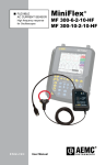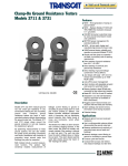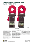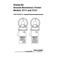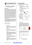
1
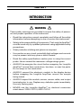
FLEXIBLE AC CURRENT PROBE ! 600V CAT. III RANGE 2 POWER RANGE 1 LOW BAT RANGE 1: RANGE 2: LongLife AmpFlex® 15 Faraday Drive • Dover NH 03820 MADE IN USA BATTERY: 9V, NEDA 1604, 6LF22, 6LR61 ENGLISH User Manual LongLife AmpFlex® Statement of Compliance Chauvin Arnoux®, Inc. d.b.a. AEMC® Instruments certifies that this instrument has been calibrated using standards and instruments traceable to international standards. We guarantee that at the time of shipping your instrument has met its published specifications. An NIST traceable certificate may be requested at the time of purchase, or obtained by returning the instrument to our repair and calibration facility, for a nominal charge. The recommended calibration interval for this instrument is 12 months and begins on the date of receipt by the customer. For recalibration, please use our calibration services. Refer to our repair and calibration section at www.aemc.com. Serial #: _ ________________________________ Catalog #:________________________________ Model #:_ ________________________________ Please fill in the appropriate date as indicated: Date Received: __________________________________ Date Calibration Due: ________________________ Chauvin Arnoux®, Inc. d.b.a AEMC® Instruments www.aemc.com Table of Contents 1. INTRODUCTION................................................................................ 2 1.1 1.2 1.3 1.4 1.5 International Electrical Symbols.................................................3 Definition of Measurement Categories......................................3 Receiving Your Shipment...........................................................3 Packaging..................................................................................4 Ordering Information..................................................................4 2. PRODUCT FEATURES....................................................................... 5 2.1 Description.................................................................................5 2.2 Features.....................................................................................6 2.3 Control Features........................................................................6 3. SPECIFICATIONS............................................................................. 8 3.1 3.2 3.3 3.4 Electrical Specifications.............................................................8 Environmental Specifications.....................................................9 Mechanical Specifications.......................................................10 Safety Specifications...............................................................10 4. OPERATION................................................................................... 11 4.1 4.2 4.3 4.4 Compatibility............................................................................ 11 Making Measurements............................................................ 11 Tips for Making Precise Measurements.................................. 11 Typical Response Curves........................................................13 5. MAINTENANCE.............................................................................. 15 5.1 Maintenance............................................................................15 Warning...................................................................................15 5.1.1 Battery Replacement...................................................15 5.1.2 Cleaning.......................................................................15 Repair and Calibration............................................................................16 Technical and Sales Assistance.............................................................16 Limited Warranty............................................................Inside back cover Warranty Repairs............................................................Inside back cover CHAPTER 1 INTRODUCTION WARNING These safety warnings are provided to ensure the safety of personnel and proper operation of the instrument. • Read this instruction manual completely and follow all the safety information before attempting to use or service this instrument. • Safety is the responsibility of the operator. The LongLife AmpFlex® must be used only by qualified personnel using applicable safety precautions. • Wear protective clothing and gloves as required. • Use caution on any circuit: potentially high voltages and currents may be present and may pose a shock hazard. • Read the safety specifications section prior to using the current probe. Never exceed the maximum voltage ratings given. • ALWAYS de-energize the circuit before wrapping the LongLife AmpFlex® around bare conductors, bus bars, or near live parts. Do not wrap on live conductors. • ALWAYS connect the electronic module to the display device before wrapping the LongLife AmpFlex® around the sample being tested. • ALWAYS inspect the module, sensor, sensor cable, and output terminals prior to use. Replace any defective parts immediately. Use only factory parts. • NEVER use the LongLife AmpFlex® on electrical conductors rated above 1000V CAT III; 600V CAT IV. 2 LongLife AmpFlex® Flexible AC Current Probe 1.1 International Electrical Symbols This symbol signifies that the instrument is protected by double or reinforced insulation. This symbol on the instrument indicates a WARNING and that the operator must refer to the user manual for instructions before operating the instrument. In this manual, the symbol preceding instructions indicates that if the instructions are not followed, bodily injury, installation/sample and product damage may result. Risk of electric shock. The voltage at the parts marked with this symbol may be dangerous. This symbol refers to a type B current sensor. Do not apply around or remove from HAZARDOUS LIVE conductors without additional protective means (deenergizing the circuit or wearing protective clothing suitable for high voltage work). 1.2 Definition of Measurement Categories Cat. I: For measurements on circuits not directly connected to the AC supply wall outlet such as protected secondaries, signal level, and limited energy circuits. Cat. II: For measurements performed on circuits directly connected to the electrical distribution system. Examples are measurements on household appliances or portable tools. Cat. III: For measurements performed in the building installation at the distribution level such as on hardwired equipment in fixed installation and circuit breakers. Cat. IV: For measurements performed at the primary electrical supply (<1000V) such as on primary overcurrent protection devices, ripple control units, or meters. 1.3 Receiving Your Shipment Upon receiving your shipment, make sure that the contents are consistent with the packing list. Notify your distributor of any missing items. If the equipment appears to be damaged, file a claim immediately with the carrier and notify your distributor at once, giving a detailed description of any damage. Save the damaged packing container to substantiate your claim. LongLife AmpFlex® Flexible AC Current Probe 3 1.4 Packaging The LongLife AmpFlex® is shipped with an electronic module, one 9V battery, user manual and a product warranty and registration card. 1.5 Ordering Information LongLife AmpFlex® - LGLF 1000-24-1-1.............................. Cat. #2120.66 LongLife AmpFlex® - LGLF 1000-24-2-1.............................. Cat. #2120.67 LongLife AmpFlex® - LGLF 3000-36-1-0.3........................... Cat. #2120.68 LongLife AmpFlex® - LGLF 3000-36-2-0.3........................... Cat. #2120.69 LongLife AmpFlex® - LGLF 6000-24-2-0.3........................... Cat. #2125.54 LongLife AmpFlex® - LGLF 6000-36-2-0.3........................... Cat. #2125.55 1.5.1 Accessories and Replacement Parts Banana (Female) / BNC (Male) Adapter.............................. Cat. #2118.46 For connection of LongLife AmpFlex® to BNC terminals on scopes and other displaying instruments. Banana (Male) / BNC (Female) Adapter.............................. Cat. #2111.32 For connection of LongLife AmpFlex® with BNC to 4mm plugs on multimeters and other displaying instruments. Order Accessories and Replacement Parts Directly Online Check our Storefront at www.aemc.com/store for availability 4 LongLife AmpFlex® Flexible AC Current Probe CHAPTER 2 PRODUCT FEATURES 2.1 Description The LongLife AmpFlex® is a flexible AC current transformer composed of a flexible sensor and an electronic module. The flexible sensor permits measurements on conductors where standard clamp-on probes could not be used. In particular, it can be installed in tight spaces, around breaker panels, around cable bundles, around wide or large bus bars, or even wrapped around irregular shapes. The Shape Memory feature enables the user to “pre-shape” the sensor, somewhat, before inserting it between or around conductors. This feature facilitates closing, enhances user safety, and alleviates the drooping effect typically associated with flexible sensors. The LongLife AmpFlex® is lightweight. It does not use magnetic cores like standard transformers. The transformation principle is based on an air core. It presents virtually no load to the system under test, has a low phase shift and excellent frequency response, and cannot be damaged by overloads. The sensor assembly is waterproof and insulated for 1000V Cat. III or 600V Cat. IV. The LongLife AmpFlex® has a mV output proportional to the current measured for direct readings on DMMs, data loggers and oscilloscopes. TRMS measurements are taken when connected to a TRMS meter. The LongLife AmpFlex® is insensitive to DC currents and only the AC component of the measured signal is measured. LongLife AmpFlex® Flexible AC Current Probe 5 2.2 6 Features • Single or dual range to measure up to 6000A • TRMS measurements when connected to a TRMS instrument • No core saturation or damage if overloaded • EN 61010, 1000V Cat. III (sensor) EN 61010, 600V Cat. III (module) • Waterproof sensor • One 9V battery for typical use of 2000 hrs continuous operation • Shape Memory for pre-shaping of sensor before use • Insensitive to DC, measures only AC component on DC + AC signals • Excellent linearity • Lightweight LongLife AmpFlex® Flexible AC Current Probe 2.3 Control Features 4 1 ! 2 600V CAT. III 5 RANGE 2 POWER RANGE 1 LOW BAT RANGE 1: RANGE 2: LongLife AmpFlex™ 3 6 15 Faraday Drive • Dover NH 03820 MADE IN USA BATTERY: 9V, NEDA 1604, 6LF22, 6LR61 7 8 Figure 1 1. Three (3) LEDs: • High range indicator • Low range indicator • Low battery indicator 2. Range selection push button 3. Electronic module 4. Lead, 6.5 ft (2m) 5. AmpFlex® connector/latch 6. Flexible sensor, Ø 0.5" (12.5mm) 7. Banana plugs: • Common: black (-) • Positive: red (+) 8. BNC connector LongLife AmpFlex® Flexible AC Current Probe 7 CHAPTER 3 SPECIFICATIONS 3.1 Electrical Specifications Model Range Output LGLF 1000-24-1-1 5 to 1000A 1mV/A (1mV for 1000A) LGLF 1000-24-2-1 5 to 100A; 50 to 1000A 10mV/A and 1mV/A (1V for 100A and 1000A) LGLF 3000-36-1-0.3 5 to 3000A LGLF 3000-36-2-0.3 0.333mV/A (1V for 3000A) Accuracy 1% of Reading ± 500mA 5 to 300A; 3.33mV/A and 0.333mV/A 50 to 3000A (1V for 300A and 3000A) LGLF 6000-24-2-0.3 5 to 600A; 3.33mV/A and 0.333mV/A LGLF 6000-36-2-0.3 50 to 6000A (2V for 600A and 6000A) Overload: 5000A max Phase Shift: <1° @ 50 to 60Hz Residual Current when I measured = 0: 500mArms Frequency Range: 40 to 5kHz Working Voltage: 1000V Cat. III, 600V Cat. IV Common Mode Voltage: 600Vrms, Cat. III Influence of Adjacent Conductor: 0.2% typical, 2% max Influence of Conductor Position: 0.5% typical, 4% max Influence of Frequency: Add 2% to the reference accuracy between 40 and 5000Hz Power Source: One 9V alkaline battery (NEDA 1604A, IEC 6LR61) 8 LongLife AmpFlex® Flexible AC Current Probe Battery Life: 2000 hrs typical, 4000 hrs max Indicators: Red LED Single Flash when low battery One Green LED Single Flash when “Low” range selected One Green LED Single Flash when “High” range selected Controls: One button used to turn ON and select range *Reference Conditions 23°C ±3°K, 20 to 70% RH, 50/60Hz, no external AC magnetic field, DC magnetic ≤ 40A/m (earth field), supply: 8V +10%. 1MΩ Load. 3.2 Mechanical Specifications Dimensions (sensor): 24" or 36" long Dimensions (module): 1.56 x 2.5 x 4.5" (40 x 64 x 114mm) Weight: 0.8 lb (13 oz) approx Maximum Conductor Size: Length 24" (Ø 7.64") Length 36" (Ø 11.46") Cable Length: 6.5 ft (2 m) sensor to case Module: UL94V2 Cable Assembly: UL94V0 Output: • Output 14" (0.35m) double insulated cable with 4mm banana plug • Insulated 2 ft (0.62m) coaxial cable with insulated BNC connector rated 600Vrms Drop Test: 1.0m on 38 mm of oak on concrete (per EN 61010) Enclosure: NEMA 4/IP65 rated LongLife AmpFlex® Flexible AC Current Probe 9 3.3 Environmental Specifications Operating Temperature: 14° to 131°F (-10° to +55°C) Storage Temperature: -4° to 158°F (-20° to +70°C) Influence of Temperature: Sensor: -10° to 100°C: < 0.5% of Reading per 10°C Module: -10° to 55°C: < 0.5% of Reading per 10°C Operating Relative Humidity: 10° to 30°C: 85 ±5% RH (without condensation) 40° to 50°C: 45 ±5% RH (without condensation) Altitude: Operating: 0 to 2000 meters Non-Operating: 0 to 12,000 meters 3.4 Safety Specifications Double insulation or reinforced insulation per IEC 1010-2-32 EN 61010 1000V Cat. III, 600V Cat. IV Pollution Degree 2 10 LongLife AmpFlex® Flexible AC Current Probe CHAPTER 4 OPERATION 4.1 Compatibility The LongLife AmpFlex® is compatible with any multimeter, AC voltmeter, or other voltage measuring instrument with an input impedance greater than 1MΩ. To achieve the best overall accuracy, use the LongLife AmpFlex® with an AC voltmeter having an accuracy of 0.75% or better. 4.2 Making Measurements • Connect the electronic module to the AC Volt range of your DMM or measuring instrument. Select the appropriate module output voltage range. If the current magnitude is unknown, select the high range output setting. • Wrap the flexible core around the conductor to be tested. If possible, select the higher mV/A output range to obtain the best resolution. Do not exceed specified current range for the output. • Read the displayed value on the DMM and divide it by the range selected (e.g. for 1000A model, if reading = 900mV with the low range, the current flowing through the probe is 900mV ÷ 10 = 90A). • True RMS measurements are obtained when the LongLife AmpFlex® is connected to a True RMS meter. Note that the DC component is not measured. 4.3 Tips for Making Precise Measurements • When using the LongLife AmpFlex® with a meter, it is important to select the range that provides the best resolution. Failure to do this may result in measurement errors. • For best results, select the highest LongLife AmpFlex® output signal possible and the most sensitive meter range for this output. LongLife AmpFlex® Flexible AC Current Probe 11 • When a measurement approaching 100A is desired, select the high range to avoid an overload condition. • Make sure the DMM or measuring instrument can accurately measure mVAC. Certain inexpensive DMM have poor resolution and accuracy when measuring low mVAC. • For best accuracy, carefully center the conductor inside the flexible core, and avoid if possible, the proximity of other conductors which may create noise and interference, particularly near the latch (see Figure 2). • The overall measurement accuracy is the sum of the LongLife AmpFlex® accuracy and the displaying instrument accuracy. ACV COM DCV + 100A BATTERY: 9V, NEDA 1604, 6LF22, 6LR61 MADE IN USA 15 Faraday Drive • Dover NH 03820 LongLife AmpF lex ® RANGE 1: RANGE 2: LOW BAT RANGE 1 POWER RANGE 2 ! 600V CAT. III Figure 2 12 LongLife AmpFlex® Flexible AC Current Probe 4.4 Typical Response Curves Typical Frequency Response (Low Range) Error (%) 0.5 0 -0.5 -1 10 100 1000 10000 Frequency (Hz) Typical Phase Shift (Low Range) 0 Degrees -2 -4 -6 -8 -10 10 100 1000 10000 Frequency (Hz) LongLife AmpFlex® Flexible AC Current Probe 13 Typical Frequency Response (High Range) Error (%) 0.5 0 -0.5 -1 10 100 1000 10000 Frequency (Hz) Typical Phase Shift (High Range) 0 Degrees -2 -4 -6 -8 -10 10 100 1000 10000 Frequency (Hz) 14 LongLife AmpFlex® Flexible AC Current Probe CHAPTER 5 MAINTENANCE 5.1 Maintenance Warning • For maintenance use only specified replacement parts. • To avoid electrical shock, do not attempt to perform any servicing unless you are qualified to do so. • To avoid electrical shock and/or damage to the instrument, do not get water or other foreign agents into the case. • Turn the instrument OFF and disconnect the unit from all the circuits before opening the case. 5.1.1 Battery Replacement • Remove the LongLife AmpFlex® from any circuit before replacing the battery. • If the low battery indicator (red LED) blinks, replace the battery. • No LEDs should be on until the “PRESS” button is pushed. • If one of the green LEDs does not blink when the “PRESS” button is pushed, check the battery for extremely low level. To replace the battery, open the rear case, replace the battery and reassemble. 5.1.2 Cleaning • It is important to keep the probe sensor latch mating surfaces clean and prevent foreign matter from entering the closing. • The sensor may be gently cleaned with a soft cloth, soap and water. Dry immediately after cleaning. Avoid water penetration into the electronic module. • Make sure the sensor, electronic module, and all leads are completely dry before any further use. LongLife AmpFlex® Flexible AC Current Probe 15 Repair and Calibration To ensure that your instrument meets factory specifications, we recommend that it be scheduled back to our factory Service Center at one-year intervals for recalibration, or as required by other standards or internal procedures. For instrument repair and calibration: You must contact our Service Center for a Customer Service Authorization Number (CSA#). This will ensure that when your instrument arrives, it will be tracked and processed promptly. Please write the CSA# on the outside of the shipping container. If the instrument is returned for calibration, we need to know if you want a standard calibration, or a calibration traceable to N.I.S.T. (Includes calibration certificate plus recorded calibration data). Ship To: Chauvin Arnoux®, Inc. d.b.a. AEMC® Instruments 15 Faraday Drive Dover, NH 03820 USA Phone:(800) 945-2362 (Ext. 360) (603) 749-6434 (Ext. 360) Fax: (603) 742-2346 or (603) 749-6309 E-mail:[email protected] (Or contact your authorized distributor) Costs for repair, standard calibration, and calibration traceable to N.I.S.T. are available. NOTE: You must obtain a CSA# before returning any instrument. Technical and Sales Assistance If you are experiencing any technical problems, or require any assistance with the proper operation or application of your instrument, please call, mail, fax or e-mail our technical support team: Chauvin Arnoux®, Inc. d.b.a. AEMC® Instruments 200 Foxborough Boulevard Foxborough, MA 02035 USA Phone:(800) 343-1391 (508) 698-2115 Fax: (508) 698-2118 E-mail:[email protected] www.aemc.com NOTE: Do not ship Instruments to our Foxborough, MA address. 16 LongLife AmpFlex® Flexible AC Current Probe Limited Warranty The LongLife AmpFlex® is warranted to the owner for a period of one year from the date of original purchase against defects in manufacture. This limited warranty is given by AEMC® Instruments, not by the distributor from whom it was purchased. This warranty is void if the unit has been tampered with, abused or if the defect is related to service not performed by AEMC® Instruments. For full and detailed warranty coverage, please read the Warranty Coverage Information, which is attached to the Warranty Registration Card (if enclosed) or is available at www.aemc.com. Please keep the Warranty Coverage Information with your records. What AEMC® Instruments will do: If a malfunction occurs within the one-year period, you may return the instrument to us for repair, provided we have your warranty registration information on file or a proof of purchase. AEMC® Instruments will, at its option, repair or replace the faulty material. REGISTER ONLINE AT: www.aemc.com Warranty Repairs What you must do to return an Instrument for Warranty Repair: First, request a Customer Service Authorization Number (CSA#) by phone or by fax from our Service Department (see address below), then return the instrument along with the signed CSA Form. Please write the CSA# on the outside of the shipping container. Return the instrument, postage or shipment pre-paid to: Ship To: Chauvin Arnoux®, Inc. d.b.a. AEMC® Instruments 15 Faraday Drive • Dover, NH 03820 USA Phone:(800) 945-2362 (Ext. 360) (603) 749-6434 (Ext. 360) Fax: (603) 742-2346 or (603) 749-6309 E-mail:[email protected] Caution: To protect yourself against in-transit loss, we recommend you insure your returned material. NOTE: You must obtain a CSA# before returning any instrument. 07/08 99-MAN 100263 v6 Chauvin Arnoux®, Inc. d.b.a. AEMC® Instruments 15 Faraday Drive • Dover, NH 03820 USA • Phone: (603) 749-6434 • Fax: (603) 742-2346 www.aemc.com