1
EP010
Modbus/FBP Interface
User and Operator Manual
ABB SACE
EP010
1SDH000510R0001
L3116
EN
INDEX
1.
Introduction . . . . . . . . . . . . . . . . . . . . . . . . . . . . . . . . . . . . . . . . . . . . . . . . . . . . . . 3
1.1
1.2
Applicability . . . . . . . . . . . . . . . . . . . . . . . . . . . . . . . . . . . . . . . . . 3
Acronyms and Definitions . . . . . . . . . . . . . . . . . . . . . . . . . . . . . . 3
1.2.1 Acronyms . . . . . . . . . . . . . . . . . . . . . . . . . . . . . . . . . . . . . . . . . . . . . . . . . . . . . . . .3
1.2.2 Definitions . . . . . . . . . . . . . . . . . . . . . . . . . . . . . . . . . . . . . . . . . . . . . . . . . . . . . . .3
1.3
2.
Bibliography . . . . . . . . . . . . . . . . . . . . . . . . . . . . . . . . . . . . . . . . . 3
Device independent section . . . . . . . . . . . . . . . . . . . . . . . . . . . . . . . . . . . . . . . . . 4
2.1
2.2
Purpose and connection of EP010 . . . . . . . . . . . . . . . . . . . . . . . . 4
EP010 description . . . . . . . . . . . . . . . . . . . . . . . . . . . . . . . . . . . . 5
2.2.1 FieldBusPlug connector . . . . . . . . . . . . . . . . . . . . . . . . . . . . . . . . . . . . . . . . . . . . .5
2.2.2 Modbus terminals . . . . . . . . . . . . . . . . . . . . . . . . . . . . . . . . . . . . . . . . . . . . . . . . .6
2.2.3 LEDs . . . . . . . . . . . . . . . . . . . . . . . . . . . . . . . . . . . . . . . . . . . . . . . . . . . . . . . . . . .6
2.3
Electrical connections . . . . . . . . . . . . . . . . . . . . . . . . . . . . . . . . . 7
2.3.1 Earthing . . . . . . . . . . . . . . . . . . . . . . . . . . . . . . . . . . . . . . . . . . . . . . . . . . . . . . . . .7
2.4
Addressing . . . . . . . . . . . . . . . . . . . . . . . . . . . . . . . . . . . . . . . . . . 8
2.4.1 EP010 addressing . . . . . . . . . . . . . . . . . . . . . . . . . . . . . . . . . . . . . . . . . . . . . . . . .8
2.4.2 FieldBusPlug addressing . . . . . . . . . . . . . . . . . . . . . . . . . . . . . . . . . . . . . . . . . . . .8
2.4.3 Modbus device addressing . . . . . . . . . . . . . . . . . . . . . . . . . . . . . . . . . . . . . . . . . .8
2.5
2.6
Replacement of a defective EP010 . . . . . . . . . . . . . . . . . . . . . . . 8
Technical data . . . . . . . . . . . . . . . . . . . . . . . . . . . . . . . . . . . . . . . 9
2.6.1
2.6.2
2.6.3
2.6.4
2.6.5
2.6.6
General data . . . . . . . . . . . . . . . . . . . . . . . . . . . . . . . . . . . . . . . . . . . . . . . . . . . . .9
Power supply for EP010 . . . . . . . . . . . . . . . . . . . . . . . . . . . . . . . . . . . . . . . . . . . .9
Connection of the FieldBusPlug . . . . . . . . . . . . . . . . . . . . . . . . . . . . . . . . . . . . . .9
Connection to a Modbus device . . . . . . . . . . . . . . . . . . . . . . . . . . . . . . . . . . . . . .9
LED displays . . . . . . . . . . . . . . . . . . . . . . . . . . . . . . . . . . . . . . . . . . . . . . . . . . . .10
Mechanical data . . . . . . . . . . . . . . . . . . . . . . . . . . . . . . . . . . . . . . . . . . . . . . . . . .10
2.7
2.8
Identification . . . . . . . . . . . . . . . . . . . . . . . . . . . . . . . . . . . . . . . . 11
Product Specification . . . . . . . . . . . . . . . . . . . . . . . . . . . . . . . . . 12
2.8.1
2.8.2
2.8.3
2.8.4
2.8.5
Start-up . . . . . . . . . . . . . . . . . . . . . . . . . . . . . . . . . . . . . . . . . . . . . . . . . . . . . . . .12
Run state . . . . . . . . . . . . . . . . . . . . . . . . . . . . . . . . . . . . . . . . . . . . . . . . . . . . . . .12
Command interface . . . . . . . . . . . . . . . . . . . . . . . . . . . . . . . . . . . . . . . . . . . . . . .13
Permanent (non volatile) information saving . . . . . . . . . . . . . . . . . . . . . . . . . . . .14
Performance data and conditions . . . . . . . . . . . . . . . . . . . . . . . . . . . . . . . . . . . .14
2.9
Diagnostics & Troubleshooting . . . . . . . . . . . . . . . . . . . . . . . . . 14
2.9.1 Diagnostics . . . . . . . . . . . . . . . . . . . . . . . . . . . . . . . . . . . . . . . . . . . . . . . . . . . . .14
2.9.2 Troubleshooting . . . . . . . . . . . . . . . . . . . . . . . . . . . . . . . . . . . . . . . . . . . . . . . . . .15
3.
Device dependent section . . . . . . . . . . . . . . . . . . . . . . . . . . . . . . . . . . . . . . . . . 16
3.1
PR222DS/PD . . . . . . . . . . . . . . . . . . . . . . . . . . . . . . . . . . . . . . . 16
3.1.1 Wiring . . . . . . . . . . . . . . . . . . . . . . . . . . . . . . . . . . . . . . . . . . . . . . . . . . . . . . . . . .16
3.1.2 Information available . . . . . . . . . . . . . . . . . . . . . . . . . . . . . . . . . . . . . . . . . . . . . .17
3.1.3 Performance data and conditions . . . . . . . . . . . . . . . . . . . . . . . . . . . . . . . . . . . .24
3.2
ABB SACE
PR122/3 with PR120/D and PR332/3 with PR330/D . . . . . . . . . 25
EP010
1SDH000510R0001
L3116
1/45
3.2.1 Wiring . . . . . . . . . . . . . . . . . . . . . . . . . . . . . . . . . . . . . . . . . . . . . . . . . . . . . . . . . .25
3.2.2 Information available . . . . . . . . . . . . . . . . . . . . . . . . . . . . . . . . . . . . . . . . . . . . . .26
3.2.3 Performance data and conditions . . . . . . . . . . . . . . . . . . . . . . . . . . . . . . . . . . . .42
4.
Revision history . . . . . . . . . . . . . . . . . . . . . . . . . . . . . . . . . . . . . . . . . . . . . . . . . . 43
4.1
4.2
4.3
Revision a - 06/10/2004 . . . . . . . . . . . . . . . . . . . . . . . . . . . . . . . 43
Revision b - 17/11/2004 . . . . . . . . . . . . . . . . . . . . . . . . . . . . . . . 43
Revision c - 06/12/2004 . . . . . . . . . . . . . . . . . . . . . . . . . . . . . . . 43
4.3.1 Modified . . . . . . . . . . . . . . . . . . . . . . . . . . . . . . . . . . . . . . . . . . . . . . . . . . . . . . . .43
4.4
Revision d - 21/12/2004 . . . . . . . . . . . . . . . . . . . . . . . . . . . . . . . 43
4.4.1 Added . . . . . . . . . . . . . . . . . . . . . . . . . . . . . . . . . . . . . . . . . . . . . . . . . . . . . . . . .43
4.4.2 Modified . . . . . . . . . . . . . . . . . . . . . . . . . . . . . . . . . . . . . . . . . . . . . . . . . . . . . . . .43
4.5
Revision e - 10/02/2005 . . . . . . . . . . . . . . . . . . . . . . . . . . . . . . . 43
4.5.1 Added . . . . . . . . . . . . . . . . . . . . . . . . . . . . . . . . . . . . . . . . . . . . . . . . . . . . . . . . .43
4.5.2 Modified . . . . . . . . . . . . . . . . . . . . . . . . . . . . . . . . . . . . . . . . . . . . . . . . . . . . . . . .44
4.6
Revision f - 04/03/2005 . . . . . . . . . . . . . . . . . . . . . . . . . . . . . . . 44
4.6.1 Added . . . . . . . . . . . . . . . . . . . . . . . . . . . . . . . . . . . . . . . . . . . . . . . . . . . . . . . . .44
4.6.2 Modified . . . . . . . . . . . . . . . . . . . . . . . . . . . . . . . . . . . . . . . . . . . . . . . . . . . . . . . .44
4.6.3 Deleted . . . . . . . . . . . . . . . . . . . . . . . . . . . . . . . . . . . . . . . . . . . . . . . . . . . . . . . .44
4.7
Revision g - 24/03/2005 . . . . . . . . . . . . . . . . . . . . . . . . . . . . . . . 44
4.7.1 Modified . . . . . . . . . . . . . . . . . . . . . . . . . . . . . . . . . . . . . . . . . . . . . . . . . . . . . . . .44
4.8
Revision h - 06/10/2005 . . . . . . . . . . . . . . . . . . . . . . . . . . . . . . . 44
4.8.1 Added . . . . . . . . . . . . . . . . . . . . . . . . . . . . . . . . . . . . . . . . . . . . . . . . . . . . . . . . .44
4.8.2 Modified . . . . . . . . . . . . . . . . . . . . . . . . . . . . . . . . . . . . . . . . . . . . . . . . . . . . . . . .45
4.9
Revision i - 25/08/2006 . . . . . . . . . . . . . . . . . . . . . . . . . . . . . . . 45
4.9.1 Added . . . . . . . . . . . . . . . . . . . . . . . . . . . . . . . . . . . . . . . . . . . . . . . . . . . . . . . . .45
4.9.2 Modified . . . . . . . . . . . . . . . . . . . . . . . . . . . . . . . . . . . . . . . . . . . . . . . . . . . . . . . .45
4.10 Revision j - 29/01/2007 . . . . . . . . . . . . . . . . . . . . . . . . . . . . . . . 45
4.10.1 Modified . . . . . . . . . . . . . . . . . . . . . . . . . . . . . . . . . . . . . . . . . . . . . . . . . . . . . . . .45
ABB SACE
EP010
1SDH000510R0001
L3116
2/45
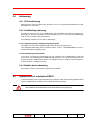
1. INTRODUCTION
This is the User and Operator Manual for the EP010, the generic ABB SACE Modbus / FieldBusPlug Interface.
It contains two sections:
1. information independent from the device connected to the Modbus port (in the following
‘device’)
2. information dependent from the device
1.1
Applicability
This document applies to all the EP010 versions.
1.2
Acronyms and Definitions
1.2.1 Acronyms
CB
EDS
FBP
GSD
HMI
LED
RX
TX
WD
Circuit Breaker
(DeviceNet) Electronic Data Sheet
FieldBusPlug
(Profibus) Gerätestammdaten
En: device data base (literal) or Generic Station Description
Human Machine Interface
Light Emitting Diode
Transmission
Reception
Watchdog
1.2.2 Definitions
1.3
Device
a device connected to the EP010 Modbus port
Interface
the EP010
Bibliography
[1]
ABB SACE
http://www.abb.com
Products & Services – ABB Product Guide –Low Voltage Products – Support: Documentations – Control Products – Fieldbus Devices
EP010
1SDH000510R0001
L3116
3/45
45
2. DEVICE INDEPENDENT SECTION
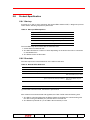
2.1
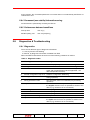
Purpose and connection of EP010
The Modbus/Fieldbus Interface EP010 establishes together with the FieldBusPlug a connection between a field bus and the device connected to the EP010 Modbus port.
In particular, EP010 acts as a communication gateway between FieldBusPlug and Modbus
device.
Power supply for EP010 comes directly from the FieldBusPlug. The connected device, however, must have its own power supply.
$
($2
'2
. #
&GXKEG
Figure 1. Concept Diagram
ABB SACE
EP010
1SDH000510R0001
L3116
4/45
45
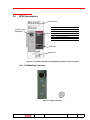
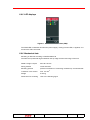
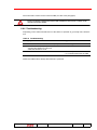
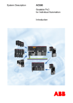
2.2
EP010 description
Protective Earth
Connector for the
FieldBusPlug
LED
Colour Description
WD
Red
Watchdog fired
PWR
Green
Power supply status
TX
Green
Modbus Transmission activity status
RX
Green
Modbus Receiving activity status
FAULT
Yellow
Fault indication
FBP
Green
FBP communication status
Reset button
Modbus port
Figure 2. Terminals, indicators and operating elements on the front plate
2.2.1 FieldBusPlug connector
male
Figure 3. FBP port socket
ABB SACE
EP010
1SDH000510R0001
L3116
5/45
45
Table 1. FBP port pins
PIN
DESCRIPTION
1
+24 V DC (standard power supply unit)
2
Diagnostic request trigger
3
0 V DC (standard power supply unit)
4
Serial data (TX)
5
Serial data (RX)
Wrong power supply polarity or swap between bus lines and power supply lines can cause a
destruction of the EP010!
The FieldBusPlug is plugged into this connector and fixed using the supplied fixing screw.
2.2.2 Modbus terminals
Figure 4. Modbus port terminals
The Modbus Port is the lowest terminal box of the EP010, with the following meaning:
Table 2. Modbus port terminals
TERMINAL NAME
MODBUS CABLE
L (left)
A
1 (right)
B
Total length of the Modbus cable from EP010 to connected device has to be less or equal to 1 m.
2.2.3 LEDs
The TX/RX communication status of the Modbus port is indicated by green LEDs. LED on
means:
- TX: Modbus message sending
- RX: Modbus message receiving
They switch according to the communication messages traffic.
ABB SACE
EP010
1SDH000510R0001
L3116
6/45
45
The presence of the power supply from the FBP is indicated by a green LED (PWR).
If the unit detects an error, this is indicated by a red LED (WD) or by a yellow LED (FAULT).
2.3
Electrical connections
Installation and maintenance have to be performed according to the technical rules, codes and
relevant standards e.g. EN 60204 part 1 by skilled electricians only.
Figure 5. Connections
Power supply (24V DC) for EP010 comes from the FBP. Connected Modbus device, however, must be independently powered.
2.3.1 Earthing
Terminal PE has to be connected to earth.
ABB SACE
EP010
1SDH000510R0001
L3116
7/45
45
2.4
Addressing
2.4.1 EP010 addressing
EP010 doesn’t need any addressing operation, since it is automatically addressed by FieldBusPlug when connected.
2.4.2 FieldBusPlug addressing
An address must be set on every FieldBusPlug. The possibilities for setting the address vary
depending on the type of field bus. Once the address is set, it is stored in the FieldBusPlug,
even in case of supply voltage breakdown.
The following methods can be used for addressing:
2.4.2.1 Addressing using a handheld programming unit
The address is set on the FieldBusPlug by means of the programming unit.
The ABB FBP Addressing Interface (CAS21-FBP.0, Order n. 1SAJ929003R0001) is the requested handheld programming unit.
2.4.2.2 Addressing via the field bus
In this case, the address is transmitted from the controller to the FieldBusPlug via the field
bus (refer to corresponding FBP FieldBusPlug description, see [1] http://www.abb.com Products & Services – ABB Product Guide –Low Voltage Products – Support: Documentations –
Control Products – Fieldbus Devices).
2.4.3 Modbus device addressing
See Table 3. Device communication parameters for details.
2.5
Replacement of a defective EP010
A defective EP010 can be replaced without any problems. After disconnecting Modbus cables
and the FieldBusPlug, the EP010 can be dismounted and replaced.
Remember that the address associated to the device via the EP010 is stored into the FBP. Therefore,
after installation, the new EP010 takes on the same address as the replaced one.
ABB SACE
EP010
1SDH000510R0001
L3116
8/45
45
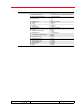
2.6
Technical data
2.6.1 General data
Total dissipation max.
432 mW
Conductor cross section
of the connection terminals
max. 2.5 mm2
2.6.2 Power supply for EP010
Supply voltage
24 V DC via FieldBusPlug
Current consumption
via FieldBusPlug max. 18 mA
2.6.3 Connection of the FieldBusPlug
Mounting
Plug connection, fastening with supplied screw
Suitable ABB FieldBusPlug types DeviceNet
PROFIBUS DP
yes
yes (PDP22-FBP only)
EP010 supports only the “long serial protocol” to communicate with the FBP. Therefore, the AS-i P
and AS-i Fieldbus Plugs cannot be used with EP010.
When a Profibus FBP is used, the relevant GSD file is required.
When a DeviceNet FBP is used, the relevant EP010 EDS file associated to the connected device is required.
They can be downloaded from the ABB web site.
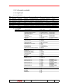
2.6.4 Connection to a Modbus device
Device communication parameters have to be:
Table 3. Device communication parameters
ABB SACE
Slave Address
247 (0xF7)
Baudrate
19200
Parity
Even
Stop bits
1
Addressing Type (where applicable)
Standard
EP010
1SDH000510R0001
L3116
9/45
45
2.6.5 LED displays
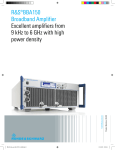
Figure 6. Human Machine Interface (HMI)
The PWR LED is switched ON when the power supply, coming from the FBP, is applied, so it
means also ‘FBP connected’.
2.6.6 Mechanical data
Mounting on DIN rail according to DIN EN 50022-35
The DIN rail is positioned aligned between the top edge and the lower edge of the unit.
ABB SACE
Width x Height x Depth
36 x 90 x 62 mm
Wiring method
screw terminals
Mounting position
preferred orientation of connecting terminals up- and downwards
Conductor cross section
max. 2.5 mm2
Weight
0.102 kg
Dimensions for mounting
refer to the following figure
EP010
1SDH000510R0001
L3116
10/45
45
Figure 7. Dimensions for mounting
2.7
Identification
Serial number is used to identify the version of EP010 and the Modbus Device which can be
connected to it.
Serial Number (S/N) has the following format:
A
N1
N2
N3
N4
F
R
R
G
Where ‘RR’ (two digits) is the version of EP010, while ‘G’ (one character) is related to the connectable Modbus device.
Important: at the end of start-up, the WD LED flashes at 0.5 Hz a number of times that’s device dependent. This way, the type of device that can be connected to an EP010 unit can be
immediately identified in field.
Value of G field and number of WD LED flashes for each device type is reported in the relevant chapter of the device-dependent section of this manual.
ABB SACE
EP010
1SDH000510R0001
L3116
11/45
45
2.8
Product Specification
2.8.1 Start-up
At power up or after a reset, beginning with all the LEDs switched OFF, a diagnostic process
starts and the following sequence is performed:
Table 4. Start-up LEDs sequence
Step
LED
Color
ON
1
WD
Red
Power-on
2
RX
Green
RAM and Code Tests passed
3
FBP
Green
External clock ready
4
FAULT
Yellow
Diagnostic completed
5
TX
Green
Ready
Then all LEDs stay ON for about 500 ms. After this time:
1. All the LEDs are switched OFF
2. The WD LED flashes a number of times depending on the device that can be connected
on the Modbus Port.
3. The EP010 enters the Run state.
2.8.2 Run state
The table reports the normal behaviour of the LEDs in this state
Table 5. Normal LEDs behaviour
LED
Color
ON
OFF
FLASHING
PWR
Green
FBP connected
FBP disconnected (1)
WD
Red
Watchdog expired
TX
Green
EP010 doesn’t communicate with FBP
EP010 communicates with FBP
AND sends Modbus query to device
RX
Green
EP010 doesn’t communicate with FBP OR
gets no response from device (if TX flashes)
EP010 communicates with FBP
AND receives Modbus response
from device
FAULT
Yellow
FBP
Green
See Diagnostics & Troubleshooting
FBP doesn’t communicate with EP010
FBP communicates with EP010
(1) If the FBP is disconnected, the EP010 is powered off.
After a failure has been detected and signalled, the FAULT LED continues flashing until:
1. The FBP is communicating with the EP010 (and then the EP010 is communicating with
the device using the Modbus port) and the fault is removed OR
2. The EP010 is powered off (i.e. the FBP is disconnected) or reset
ABB SACE
EP010
1SDH000510R0001
L3116
12/45
45
While in run state, EP010 can be in one of the following conditions:
1. FBP communicating with EP010, connected Modbus device responding (see 2.8.2.2
Communication with the Modbus device): this is the normal working condition
2. FBP not communicating (see 2.8.2.1 Communication with the FBP)
3. FBP communicating, device not responding (see 2.9.1 Diagnostics) (see 2.9.2 Troubleshooting).
2.8.2.1 Communication with the FBP
Status of the communication between EP010 and FBP is indicated by the FBP green LED:
flashing means communication is working, OFF means no communication.
2.8.2.2 Communication with the Modbus device
EP010 works by polling the connected device, i.e., sending Modbus telegrams (queries) to
the Modbus device and receiving responses (response telegrams) from it.
Modbus RTU query sending from EP010 to the device is started when the FBP communication between FBP and the EP010 is started.
Modbus RTU communication between EP010 and the device (i.e. stop query sending) is
stopped when the communication between the FBP and the EP010 is stopped.
EP010 considers Modbus device to be ‘disconnected’ when there is a checksum (CRC) error
in a response telegram, or there is no response after 4 attempts (retries) to send the same
query. When this happens, EP010 stops asking the device for data, and it starts sending probe queries ("Report Slave ID") to check when the device resumes communication, then starts
polling data again.
When the communication between the EP010 and the device fails, the EP010 data are neither
updated nor reset: they are frozen until the communication has been restored.
2.8.3 Command interface
It’s possible to issue a command to the EP010 using two different interfaces:
1. Cyclic, realized with an Analog Input process variable
2. Acyclic, realized with a Parameter (parameter number 1)
The cyclic interface sends continually the command while the acyclic one send it once.
Both interfaces use the following format:
Table 6. Command format
ABB SACE
WORD
DESCRIPTION
1st (Least Significant Word)
Command value
2nd (Most Significant Word)
Command parameter
EP010
1SDH000510R0001
L3116
13/45
45
At the moment, the ‘Command parameter’ is not used and it’s not evaluated by the EP010. Its
value doesn’t care.
2.8.4 Permanent (non volatile) information saving
No information is permanently saved by the EP010.
2.8.5 Performance data and conditions
2.9
Start-up time
max. 3 [s]
Modbus polling rate
max. 52 [ms/query]
Diagnostics & Troubleshooting
2.9.1 Diagnostics
There are two different type of diagnostic information:
1. Local, by FAULT LED flashing
2. Remote, by diagnostic information available from FBP
When the FAULT LED flashes at least one of the following conditions is verified:
Table 7. Diagnostic codes
#
Meaning
Description
1.
No device communication
No device physically connected OR message CRC error
2.
Wrong device connected
The connected device Slave ID is NOT the right one
3.
Device not initialised
The connected device has not been correctly initialised
at the end of manufacturing (where applicable - see
device dependent sections)
4.
Internal configuration map error Software configuration tables bug
5.
Wrong parameter number
The requested parameter number doesn’t exist (only for
writing operation)
6.
Wrong parameter value
The parameter value is not allowed (only for writing
operation)
7.
Acycllic command not executed The command is correctly received by the EP010 from
the acyclic section but it’s not possible to send it to the
device (e.g. the device is not connected).
8.
Watchdog fault
Start-up diagnostics
9.
Modbus UART fault
Start-up diagnostics
10. RS 485 driver fault
Start-up diagnostics
11. Cyclic command wrong value
The cyclic command value is not correct
12. Cyclic command not executed
The command is correctly received by the EP010 from
the cyclic section but it’s not possible to send it to the
device (e.g. the device is not connected).
ABB SACE
EP010
1SDH000510R0001
L3116
14/45
45
The exact failure cause can be read from FBP (see also next paragraph).
Please note that NO communication between FBP and EP010 is active if there is a failure on the
relevant serial channel (UART).
2.9.2 Troubleshooting
Depending on the status and behaviour of the LEDs it’s possible to get locally some information:
Table 8. Troubleshooting
#
Symptom
Diagnosis
1.
Some or all LEDs still ON after start-up sequence SW/HW bug
2.
- TX LED flashes (very fast) and
- FAULT LED flashes at 2 Hz and
- FBP LED flashes at 2 Hz
No response from the device
3.
FAULT LED flashes at 2 Hz
- Previously detected fault and
- no communication with the FBP
NOTE: the PWR LED is always ON if EP010 is powered.
ABB SACE
EP010
1SDH000510R0001
L3116
15/45
45
3. DEVICE DEPENDENT SECTION
3.1
PR222DS/PD
This user manual applies to the following EP010 SW versions:
1. PR222DS/PD FBP Interface v01.00 or higher
Order Code
Description
S/N Product Type field (G)
WD LED number of flash
FBP Product Code
1SDA059469R1
PR222DS/PD FBP Interface
A
1
20001 (0x4E21)
3.1.1 Wiring
EP010
X3 Connector
L (A)
1 (B)
1 (A)
2 (B)
Tmax
3 (-Vaux)
4 (+Vaux)
Figure 8. EP010 – PR222DS/PD wiring diagram
ABB SACE
EP010
1SDH000510R0001
L3116
16/45
45
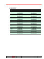
3.1.2 Information available
3.1.2.1 Digital input
3.1.2.1.1 Structure
Bit No.
Byte No.0
7
Any Trip
6
Any Alarm
Byte No.1
Manual/Electronic
Parameters Settings
L alarm
Programmng Fail
Programming OK
L pre-alarm
Trip data available
General Purpose I/O
Manual parameters
changed
CB Tripped
Manual parameters error
General Purpose I/O
MOE-E unknown
Byte No.7
General Purpose I/O
Electronic parameters
changed
CB Open/Closed
EEPROM parameters
error
G alarm
Byte No.8
Byte No.9
S tripped
NOT USED
Byte No.2
Byte No.3
Byte No.4
Byte No.5
Byte No.6
5
Test Unit connected
4
Self Supply
3
2
Electronic Trip Test CB command
executed
Operating Mode Local/ Other Trip
Trip Command Fail
Remote
Serial parameters
Nominal current
AUX-E error
unknown
unknown
General Purpose I/O General Purpose I/O MOE-E overheated
Wink Status
G tripped
I tripped
1
Electronic parameters
changed
CB Open/Close d
0
Manual parameters
changed
CB Tripped
EEPROM parameters
error
G alarm
S tripped
Manual parameters error
S alarm
L tripped
Any Alarm
Programmng Fail
Electronic Trip Test
Other Trip
CB command executed
Trip Command Fail
S alarm
Any Trip
Manual/Electronic
Parameters Settings
L alarm
L tripped
NOT USED
General Purpose I/O
NOT USED
General Purpose I/O
NOT USED
L pre-alarm
Test Unit connected Self Supply
Programmi ng OK
Operating Mode Local/
Remote
Trip data available Serial parameters
unknown
General Purpose I/O General Purpose I/O
NOT USED
NOT USED
Nominal current unknown AUX-E error
General Purpose I/O
G tripped
MOE-E overheated
I tripped
3.1.2.1.2 Details
BINARY INPUT
Number of variables 74
Number of bytes 10
#
0
Name / Description
Manual parameters changed
Coding / Range
1 = Parameters changed
Notes
Reset after read
1
2
3
4
Electronic parameters changed
CB command executed
Electronic Trip Test
Self Supply
Reset after read
Reset after read
Reset after read
Reset after read
5
6
7
8
9
Test Unit connected
Any Alarm
Any Trip
CB Tripped
CB Open/Closed
1 = Parameter changed
1 = CB command executed
1 = Trip
0 = OFF
1 = ON
1 = Test Unit connected
1 = Any alarm
1 = Any trip
1 = CB tripped
0 = CB Open
1 = CB Closed
1 = Trip command failed
1 = Trip
0 = Remote
1 = Local
1 = Programming OK
1 = Programming Failed
0 = Electronic
1 = Manual
1 = Error
1 = Error
1 = Error
1 = Unknown
1 = Unknown
1 = Available
1 = Pre-alarm
1 = Alarm
1 = Alarm
1 = Alarm
1 = Overheated
1 = Closed
0 = Open
1 = Closed
0 = Open
1 = Closed
0 = Open
1 = Closed
0 = Open
1 = Closed
0 = Open
10 Trip Command Fail
11 Other Trip
12 Operating Mode Local/Remote
13 Programming OK
14 Programmng Fail
15 Manual/Electronic Parameters Settings
16
17
18
19
20
21
22
23
24
25
26
27
Manual parameters error
EEPROM parameters error
AUX-E error
Nominal current unknown
Serial parameters unknown
Trip data available
L pre-alarm
L alarm
S alarm
G alarm
MOE-E overheated
General Purpose I/O
28 General Purpose I/O
29 General Purpose I/O
30 General Purpose I/O
31 General Purpose I/O
32
33
34
35
36
ABB SACE
L tripped
S tripped
I tripped
G tripped
Wink Status
EP010
Reset after read
OR of alarms, pre-alarms
OR of trips
NOT USED, FUTURE
EXTENSIONS
NOT USED, FUTURE
EXTENSIONS
NOT USED, FUTURE
EXTENSIONS
NOT USED, FUTURE
EXTENSIONS
NOT USED, FUTURE
EXTENSIONS
1 = Trip
1 = Trip
1 = Trip
1 = Trip
0 = OFF
1 = ON
1SDH000510R0001
L3116
17/45
45
BINARY INPUT
#
37
38
39
40
41
42
Name / Description
MOE-E unknown
Manual parameters changed
Electronic parameters changed
CB command executed
Electronic Trip Test
Self Supply
43
44
45
46
47
Test Unit connected
Any Alarm
Any Trip
CB Tripped
CB Open/Closed
48 Trip Command Fail
49 Other Trip
50 Operating Mode Local/Remote
51 Programming OK
52 Programmng Fail
53 Manual/Electronic Parameters Settings
54
55
56
57
58
59
60
61
ABB SACE
Manual parameters error
EEPROM parameters error
AUX-E error
Nominal current unknown
Serial parameters unknown
Trip data available
L pre-alarm
L alarm
EP010
Coding / Range
1 = Unknown
1 = Parameters changed
1 = Parameter changed
1 = CB command executed
1 = Trip
0 = OFF
1 = ON
1 = Test Unit connected
1 = Any alarm
1 = Any trip
1 = CB tripped
0 = CB Open
1 = CB Closed
1 = Trip command failed
1 = Trip
0 = Remote
1 = Local
1 = Programming OK
1 = Programming Failed
0 = Electronic
1 = Manual
1 = Error
1 = Error
1 = Error
1 = Unknown
1 = Unknown
1 = Available
1 = Pre-alarm
1 = Alarm
1SDH000510R0001
Notes
TRIP REPORTS start here!
L3116
18/45
45
3.1.2.2 Analog input
3.1.2.2.1 Structure
15...8
7...0
MSB
LSB
Word 0
L1 run time current
(most significant byte)
L1 run time current
(least significant byte)
Word 1
L2 run time current
(most significant byte)
L2 run time current
(least significant byte)
Word 2
L3 run time current
(most significant byte)
L3 run time current
(least significant byte)
Word 3
N run time current
(most significant byte)
N run time current
(least significant byte)
Word 4
Ground run time current
(most significant byte)
Ground run time current
(least significant byte)
Word 5
L1 trip current
(most significant byte)
L1 trip current
(least significant byte)
Word 6
L2 trip current
(most significant byte)
L2 trip current
(least significant byte)
Word 7
L3 trip current
(most significant byte)
L3 trip current (
least significant byte)
Word 8
N trip current
(most significant byte)
N trip current
(least significant byte)
Word 9
Ground trip current
(most significant byte)
Ground trip current
(least significant byte)
Word 10
CB number of operations
(most significant byte)
CB number of operations
(least significant byte)
Word 11
CB number of protections trips
(most significant byte)
CB number of protections trips
(least significant byte)
Word 12
L number of trips
(most significant byte)
L number of trips
(least significant byte)
Word 13
S number of trips
(most significant byte)
S number of trips
(least significant byte)
Word 14
I number of trips
(most significant byte)
I number of trips
(least significant byte)
Word 15
G number of trips
(most significant byte)
G number of trips
(least significant byte)
Bit No.
ABB SACE
EP010
1SDH000510R0001
L3116
19/45
45
3.1.2.2.2 Details
ANALOG INPUT
Number of variables
Number of bytes
16
32
#
0
1
2
3
4
5
6
7
8
9
10
11
12
13
14
15
Name / Description
L1 run time current
L2 run time current
L3 run time current
N run time current
Ground run time current
L1 trip current
L2 trip current
L3 trip current
N trip current
Ground trip current
CB number of operations
CB number of protections trips
L number of trips
S number of trips
I number of trips
G number of trips
Range Coding Units
A | In
A | In
A | In
A | In
A | In
A | In
A | In
A | In
A | In
A | In
Multiplier for Length
[bytes] range
2
2
2
2
2
2
2
2
2
2
2
2
2
2
Notes
see note 1
see note 1
see note 1
see note 1
see note 1
see note 1
see note 1
see note 1
see note 1
see note 1
Note 1
Their values are expressed as percentage of IN if the Nominal current is not set (i.e. the event ‘Nominal current unknown’ =1, see
Digital inputs), otherwise (i.e. the event ‘Nominal current unknown’=0) in Ampere.
Example: value read 150
- Nominal current unknown -> 1.5 IN
- Nominal current known -> 1.5 A
3.1.2.3 Analog output
3.1.2.3.1 Structure
Bit No.
15...8
7...0
MSB
LSB
Word 0
Command info - value
(most significant byte of 2 bytes)
Command info - value
(least significant byte of 2 bytes)
Word 1
Command info - parameter
(most significant byte of 2 bytes)
Command info - parameter
(least significant byte of 2 bytes)
3.1.2.3.2 Details
ANALOG INPUT
Number of variables
2
#
0
Name / Description
(Cyclic) Command info - value
CB Open
CB Close
CB Reset
Trip Reset
(Cyclic) Command info - parameter
Range
No command
Coding Length [bytes]
0
2
1
2
3
4
2
Notes
see note 1
Number of bytes
4
1
Don't care
see note 1
Note 1
When you want to send commands, write these 2AO at the same time, putting a dummy value for the “Command info - parameter”.
ABB SACE
EP010
1SDH000510R0001
L3116
20/45
45
3.1.2.4 Diagnostics
3.1.2.4.1 Structure
Word No.
Word 0
Bit No.
Byte no. 0
Byte no. 1
7
Diagnostics
present
NOT USED
6
Acyclic command
not executed
NOT USED
5
Wrong parameter
value
NOT USED
4
3
2
Wrong parameter Internal configuration
Device no
number
map error
initialized
Cyclic command not
Cyclic command
RS 485 driver
executed
wrong value
fault
1
Wrong device
connected
Modbus UART
fault
0
No device
communication
Watchdog fault
3.1.2.4.2 Details
DIAGNOSTICS
Number of variables
Number of bytes
ABB SACE
1
2
#
0
1
2
3
4
5
6
7
8
9
10
11
12
13
14
15
Name / Description
No device communication
Wrong device connected
Device not initialized
Internal configuration map error
Wrong parameter number
Wrong parameter value
Command not executed
Diagnostics present
Watchdog fault
Modbus UART fault
RS 485 driver fault
Cyclic command wrong value
Cyclic command not executed
NOT USED
NOT USED
NOT USED
EP010
Coding
Notes
See Table 7.
See Table 7.
See Table 7.
See Table 7.
See Table 7.
See Table 7.
See Table 7.
1 = Diagnostics present
1SDH000510R0001
See Table 7.
See Table 7.
See Table 7.
See Table 7.
See Table 7.
L3116
21/45
45
3.1.2.5 Parameters
3.1.2.5.1 Details
Param. length in
No.
bytes
Typ Parameter
1
4
r/w Command info:
byte 0-1: command value
2
3
2
2
r
r
byte 2-3; command parameter
Protection L manual trip level
Protection L manual trip delay
4
5
6
2
2
2
r
r
r
Protection S manual trip level
Protection S manual trip delay
Protection I manual trip level
7
8
9
2
2
2
r
r
r
Protection G manual trip level
Protection G manual trip delay
First bit field:
0: Neutral selection
1: Neutral enabling
2: Protection S manual disable
3: Protection S manual curve type
4: Protection I manual disable
5: Protection G manual disable
11
12
2
2
r
r
6 - 15: not used
Date of test (DD/MM/YYYY)
byte 0-1: day
byte 2-3: month
byte 4-5: year
Protection L electronic trip level
Protection L electronic trip delay
13
14
15
2
2
2
r
r
r
Protection S electronic trip level
Protection S electronic trip delay
Protection I electronic trip level
16
17
18
2
2
2
r
r
r
Protection G electronic trip level
Protection G electronic trip delay
First bit field:
0: Protection L electronic pre-alarm
disable
1: Protection S electronic disable
10
2
r
0
2: Protection S electronic curve type
0
3: Protection I electronic disable
0
4: Protection G electronic disable
19
2
r
5 - 15: not used
Product execution
20
8
r
Protection Unit serial number HI
21
8
r
Protection Unit serial number LO
22
2
r
r
r
Communication Parameters bitfield:
0 - 7: Slave Address
8: Baud rate
r
9 - 10: Parity
r
11: Addressing type
Coding
Range
No command
CB Open
CB Close
CB Reset
Trip Reset
Don't care
{0.4 … 1}, step 0.02
T4-320 | T5-630 | T5-600 UL: 3 | 6 | 9 | 12
T4 - T5: 3 | 6 | 9 | 18
S6: 3 | 6 | 9 | 18
0 (Disabled) | 0.6 | 1.2 | 1.8 | 3 | 3.6 | 4.2 | 5.8 | 6.4 | 7 | 7.6 | 8.2 | 8.8 | 9.4 | 10
0.05 | 0.1 | 0.25 | 0.5
T4-320 | T5-630 | T5-600 UL:
0 (Disabled) | 1.5 | 2.5 | 3 | 4 | 4.5 | 5 | 5.5 | 6.5 | 7 | 7.5 | 8 | 9 | 9.5 | 10 | 10
T4 - T5:
0 (Disabled) | 1.5 | 2.5 | 3 | 4 | 4.5 | 5 | 5.5 | 6.5 | 7 | 7.5 | 8 | 9 | 9.5 | 10.5 | 12
S6:
0 (Disabled) | 1.5 | 2.5 | 3 | 4 | 4
0 (Disabled) | 0.2 | 0.25 | 0.45 | 0.55 | 0.75 | 0.8 | 1
0.1 | 0.2 | 0.4 | 0.8
0
1
2
3
4
50%
100 %
Off (Disabled)
On (Enabled)
Enabled
Disabled
Definite Time
Inverse Time
Enabled
Disabled
Enabled
Disabled
0
1
0
1
0
1
0
1
0
1
Multiplier for
Range
(see note 1)
Default value
Notes
0
100
10
0
0.4
10
100
10
0
0.05
0
100
100
0
0.1
1
Off
Disabled
Definite Time
Disabled
Disabled
{1 ... 31}
{1 ... 12}
{0 ... 65535}
{0.4 … 1}, step 0.01
T4-320 | T5-630 | T5-600 UL: {3 … 12}, step 0.5
T4 - T5: {3 … 18}, step 0.5
S6: {3 … 18}, step 0.5
{0.6 … 10}, step 0.1
{0.05 … 0.5}, step 0.01
T4-320 | T5-630 | T5-600 UL: {1.5 … 10}, step 0.1
T4 - T5: {1.5 … 12}, step 0.1
S6: {1.5 … 12}, step 0.1
{0.2 … 1}, step 0.01
{0.1 … 0.8}, step 0.01
Enabled
Disabled
Enabled
Disabled
Definite Time
Inverse Time
Enabled
Disabled
Enabled
Disabled
100
10
1
18
10
100
10
10
0.05
4
100
100
1
0.8
0
1
0
1
0
1
0
1
0
1
LSI
LSIG
SI
Enabled
Disabled
Inverse Time
Enabled
Disabled
0
1
2
1 byte for
character
(ASCII)
1 byte for
character
(ASCII)
{1 … 247}
9600
19200
Even
Odd
None
ABB
Standard
LSI
see Note 2
see Note 2
247
0
1
00
01
10
0
1
Even
Standard
Note 1
If you Multiplier is present, divide the data got from the device (Coding) by this multipler to get the actual value (Range).
Note 2
FOR DEVICENET: bytes inside every word are swapped. To get the right values, they have to be swapped. Moreover, the information is truncated to 4
bytes.
FOR PROFIBUS: to get the right values, words have to be rotated. Only the number of words calculated from the ‘Length in bytes’ field (i.e. ‘Length in
bytes ‘/2) have to be rotated.
ABB SACE
EP010
1SDH000510R0001
L3116
22/45
45
Param. length in
No.
bytes
Typ Parameter
Coding
Range
Multiplier for
Range
(see note 1)
Default value
Notes
Note 3
FOR DEVICENET: bytes order is according to the Intel format (little endian).
Example: 00
00
00
00
01
00
01
00
01
00
00
00
01
00
00
01
0B
00
00
00
(hex)
(hex)
(hex)
(hex)
(hex)
RIGHT
RIGHT
WRONG
RIGHT (dummy command)
RIGHT (dummy command)
FOR PROFIBUS: bytes order is according to the Motorola format (big endian).
Example: 00
00
01
00
00
ABB SACE
01
0B
00
00
00
00
00
00
01
00
00
01
00
00
01
(hex)
(hex)
(hex)
(hex)
(hex)
RIGHT
RIGHT
WRONG
RIGHT (dummy command)
RIGHT (dummy command)
EP010
1SDH000510R0001
L3116
23/45
45
3.1.2.6 Example: PROFIBUS DP data structure
Data type
Cyclic data
exchange
Group
DI = digital input
AI = analog input
DO = digital outout
AO = analog output
Other basic
Diagnosis
data transfer Configuration, identification
Bus specific data
Block parameters
Acyclcic data Single parameters
exchange
Example
Status, alarms, trips …
Run-time measures
Not available
Commands
Faults and warnings
Not available
Not available
Not available
Device configuration,
Protection parameters ...
Quantity/Presentation
74 single Bits in 15 Bytes
16 Words
2 Words
11 single Bits in 1 Word
27 single parameters of different enghts (2, 4, 6
or 8 Bytes)
Direction
read
read
write
read
read/write
Remarks:
Diagnosis.
The diagnosis telegrams of the PROFIBUS DP slaves start with additional 2 bytes that concern the
number of diagnosis bytes and status of the slave.
Configuration: Modern fieldbuses such as PROFIBUS DP-V0, -V1 and DeviceNet fix the Configuration data using
the appropriate configuration files (e.g. “xxx.GSD”, “xxx.EDS”) and write it automatically into the
FieldBusPlug during power up.
Most of the FieldBusPlug types compare the Configuration data sent by the EP010 with the
Configuration data received from the fieldbus. When the result of the comaprison is ok, parameters
can be downloaded and the operation can start.
The Configuration data set contains the product code.
Additional to the above named data the FieldBusPlug - only the FieldBus-Plug, not the EP010 - can
send on request identification data such as vendor name, slave address and data baud rate as
defined in the appropriate FieldBus standard.
Parameters:
Depending on the fieldbus type the parameters can be:
- written as parameter block - only complete block - (e.g. PROFIBUS DP-V0) or
- written and read as single parameters (e.g. PROFIBUS DP-V1, DeviceNet)
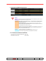
3.1.3 Performance data and conditions
Trip Reports and Currents refresh rate max. 2 [s]
Parameters refresh rate
ABB SACE
EP010
max. 20 [s]
1SDH000510R0001
L3116
24/45
45
3.2
PR122/3 with PR120/D and PR332/3 with PR330/D
This user manual applies to the following EP010 SW versions:
1. PR122/3 and PR332/3 FBP Interface v02.00 or higher, but it’s backward compatible with
the PR122/3 FBP Interface v01.xx
Order Code
Description
S/N
Product Type field (G)
WD LED
number of flash
FBP
Product Code
1SDA060198R1
PR122/3 and PR332/3 FBP Interface
B
2
20002 (0x4E22)
3.2.1 Wiring
PR122/3
PR120/D-M
L (A)
1 (B)
EP010
Figure 9. EP010 – PR122/3 wiring diagram
PR332/3
PR330/D-M
L (A)
1 (B)
EP010
Figure 10. EP010 – PR332/3 with PR330/D-M wiring diagram
ABB SACE
EP010
1SDH000510R0001
L3116
25/45
45
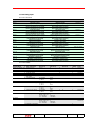
3.2.2 Information available
The device type (PR122, PR123, PR332 or PR333) can be read from Parameter n. 2.
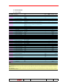
3.2.2.1 Digital input
3.2.2.1.1 Structure
Bit No.
Byte No.0
7
6
CB connected / isolated CB tripped
5
Any Trip
4
Any Alarm / Timing /
Warning
Trip command fail
Byte No.1
Programming Fail
Programming OK
Byte No.2
Signalling module
present
BT unit present
(No PR332/3)
Local / Remote Operating
Mode
Test Unit connected
Byte No.3
Wink ON
Datalogger Triggered Waiting Trigger
L Timing
ActiveDualSet
(PR123 only)
L Pre-alarm
Datalogger stopped
Byte No.4
Contact Wear Alarm
Contact Wear Prealarm
Byte No.5
T Alarm
T Pre-alarm
G Ext Alarm (Blocked Trip) G Ext Timing
Byte No.6
OV Alarm (Blocked Trip) OV Timing
UV Alarm (Blocked Trip)
UV Timing
Byte No.7
OF Alarm (Blocked Trip) OF Timing
Test Session
UF Alarm (Blocked Trip)
UF Timing
Byte No.8 N Sensor Error
L3 Sensor Error
Byte No.9 Invalid Date
Phase Cycle Error
Byte No.10 Local bus Relè 6 contact NOT USED
L2 Sensor Error
Power Factor Error
Local bus Relè 4 contact
Byte No.11 S zone selectivity output S zone selectivity input
L1 Sensor Error
Internal Error
Local bus Relè 3
contact
Relè P3 contact
(No PR332/3)
S2 tripped
(PR123 only)
UV tripped
External Input Trip
(No PR332/3)
Byte No.12 G tripped
Iinst tripped
Relè P4 contact
(No PR332/3)
I tripped
Byte No.13 RP tripped
Byte No.14 NOT USED
RV tripped
NOT USED
OV tripped
Hardware Error Trip
3
Signalling Reset
2
Waveform available
(PR123 only)
Springs charged/
No communic on Local
discharged
Bus
System Bus
Local Bus programming
programming session session
1
Historical Measures
Update
CB undefined
0
Parameters
changed
CB open/closed
Test Bus programming
session
Internal Bus
programming
session
Dialog unit present
Display Off for high temp Voltage unit present
Harmonic distortion > Waveform session
2.1
status (PR123 only)
KK function
G Alarm (Blocked
Trip)
U Alarm (Blocked
Trip)
RP Alarm (Blocked
Trip)
LC2 Alarm
Key Plug Error
Local bus Relè 2
contact
Relè P2 contact
(No PR332/3)
S tripped
G Timing
S2 Timing
(PR123 only)
D Timing
T Alarm (Blocked
(PR123 only)
Trip)
RV Alarm (Blocked Trip) RV Timing
UN tripped
Simulated Trip from
Test Unit
D tripped (PR123 only)
Electronic Trip Test
U Timing
RP Timing
LC1 Alarm
Iw Warning
Rating Plug Error
Trip Coil Error
Local bus Relè 1 contact CB Status Error
Relè P1 contact
L tripped
Signalling Module
Input Status
(No PR332/3)
S Timing
Frequency Error
GTe Sensor Error
Configuration Error
Local bus Relè 8 contact Local bus Relè 7
contact
G zone selectivity output G zone selectivity
input
T tripped
G ext tripped
OF tripped
UF tripped
3.2.2.1.2 Details
BINARY INPUT
Number of variables
Number of bytes
#
118 0
15 1
2
3
4
5
6
7
ABB SACE
Name / Description
Parameters changed
Historical Measures Update
Waveform available
Signalling Reset
Any Alarm / Timing / Warning
Any Trip
CB tripped
CB connected / isolated
8
CB open/closed
9
10
11
CB undefined
No communic on Local Bus
Springs charged/discharged
12
13
Trip command fail
Local / Remote Operating Mode
14
15
16
17
18
19
20
21
22
23
24
25
26
27
28
29
30
Programming OK
Programming Fail
Internal Bus programming session
Test Bus programming session
Local Bus programming session
System Bus programming session
Test Session
Test Unit connected
BT unit present
Signalling module present
Dialog unit present
Voltage unit present
Display Off for high temp
Waiting Trigger
Datalogger Triggered
Datalogger stopped
ActiveDualSet
31
Wink ON
32
Signalling Module Input Status
33
KK function
34
35
36
37
38
39
40
41
42
43
44
45
46
Waveform session status
Harmonic distortion > 2.1
Contact Wear Pre-alarm
Contact Wear Alarm
L Pre-alarm
L Timing
S Timing
S2 Timing
G Timing
G Alarm (Blocked Trip)
G Ext Timing
G Ext Alarm (Blocked Trip)
T Pre-alarm
Coding / Range
1 = Parameters changed
1 = Historical Measure updated
1 = Waveform available
1 = Signalling reset
1 = Any alarm
1 = Any trip
1 = CB tripped
0 = Isolated
1 = Connected
0 = Open
1 = Closed
1 = Undefined
1 = No communication on LB
0 = Discharged
1 = Charged
1 = Trip command failed
0 = Local
1 = Remote
1 = Programming OK
1 = Programming Failed
1 = Bus Internal session open
1 = Bus Test session open
1 = Bus Local session open
1 = Bus System session open
1 = Test session open
1 = Test unit connected
1 = BT unit present
1 = Signaling module present
1 = Dialog unit present
1 = Measuring unit present
1 = Display Off
1 = Waiting trigger
1 = Triggered
1 = Stopped
0 = SET A
1 = SET B
0 = OFF
1 = ON
0 = Not active
1 = Active
"0 = OFF
1 = ON
1 = Busy
1 = Harmonic distortion > 2.1
1 = Pre-alarm
1 = Alarm
1 = Pre-alarm
1 = Timing
1 = Timing
1 = Timing
1 = Timing
1 = Alarm (Blocked Trip)
1 = Timing
1 = Alarm (Blocked Trip)
1 = Pre-alarm
EP010
Notes
Reset after read
Reset after read
Reset after read
PR123/PR333 Only
Reset after read
OR of alarms, pre-alarms, timing, alarms (blocked trips), warning, errors.
OR of Trips (latched)
1SDH000510R0001
No PR332/3
PR123/PR333 Only
No PR332/3
PR123/PR333 Only
PR123/PR333 Only
L3116
26/45
45
BINARY INPUT
ABB SACE
#
47
48
49
50
51
52
53
54
55
56
57
58
59
60
61
62
63
64
65
66
67
68
69
70
71
72
73
74
75
76
77
78
79
80
81
82
Name / Description
T Alarm
T Alarm (Blocked Trip)
D Timing
U Timing
U Alarm (Blocked Trip)
UV Timing
UV Alarm (Blocked Trip)
OV Timing
OV Alarm (Blocked Trip)
RV Timing
RV Alarm (Blocked Trip)
RP Timing
RP Alarm (Blocked Trip)
UF Timing
UF Alarm (Blocked Trip)
OF Timing
OF Alarm (Blocked Trip)
Frequency Error
Iw Warning
LC1 Alarm
LC2 Alarm
L1 Sensor Error
L2 Sensor Error
L3 Sensor Error
N Sensor Error
GTe Sensor Error
Trip Coil Error
Rating Plug Error
Key Plug Error
Internal Error
Power Factor Error
Phase Cycle Error
Invalid Date
Configuration Error
CB Status Error
Local bus Relè 1 contact
Coding / Range
1 = Alarm
1 = Alarm (Blocked Trip)
1 = Timing
1 = Timing
1 = Alarm (Blocked Trip)
1 = Timing
1 = Alarm (Blocked Trip)
1 = Timing
1 = Alarm (Blocked Trip)
1 = Timing
1 = Alarm (Blocked Trip)
1 = Timing
1 = Alarm (Blocked Trip)
1 = Timing
1 = Alarm (Blocked Trip)
1 = Timing
1 = Alarm (Blocked Trip)
1 = Error
1 = Warning
1 = Alarm
1 = Alarm
1 = Error
1 = Error
1 = Error
1 = Error
1 = Error
1 = Error
1 = Error
1 = Error
1 = Error
1 = Error
1 = Error
1 = Error
1 = Error
1 = Error
0 = Open
1 = Closed
"
83
Local bus Relè 2 contact
84
Local bus Relè 3 contact
85
Local bus Relè 4 contact
0 = Open
1 = Closed
0 = Open
1 = Closed
0 = Open
1 = Closed
86
87
NOT USED
Local bus Relè 6 contact
88
Local bus Relè 7 contact
89
Local bus Relè 8 contact
90
Relè P1 contact
91
Relè P2 contact
92
Relè P3 contact
93
Relè P4 contact
94
95
96
97
98
99
100
101
102
103
104
105
106
107
108
109
110
111
112
113
114
115
116
117
118
119
S zone selectivity input
S zone selectivity output
G zone selectivity input
G zone selectivity output
L tripped
S tripped
S2 tripped
I tripped
Iinst tripped
G tripped
G ext tripped
T tripped
D tripped
UN tripped
UV tripped
OV tripped
RV tripped
RP tripped
UF tripped
OF tripped
Electronic Trip Test
Simulated Trip from Test Unit
External Input Trip
Hardware Error Trip
NOT USED
NOT USED
Notes
PR123/PR333 Only
"Temperature Sensor Error" if SW version < 1.10
0 = Open
1 = Closed
0 = Open
1 = Closed
0 = Open
1 = Closed
0 = Open
1 = Closed
0 = Open
1 = Closed
0 = Open
1 = Closed
0 = Open
1 = Closed
1 = Input active
1 = Output active
1 = Input active
1 = Output active
1 = Trip
1 = Trip
1 = Trip
1 = Trip
1 = Trip
1 = Trip
1 = Trip
1 = Trip
1 = Trip
1 = Trip
1 = Trip
1 = Trip
1 = Trip
1 = Trip
1 = Trip
1 = Trip
1 = Trip
1 = Trip
1 = Trip
1 = Trip
EP010
No PR332/3
No PR332/3
No PR332/3
PR123/PR333 Only
PR123/PR333 Only
No PR332/3
1SDH000510R0001
L3116
27/45
45
3.2.2.2 Analog input
3.2.2.2.1 Structure
15...8
Bit No.
Word 0
Word 1
Word 2
Word 3
Word 4
Word 5
Word 6
Word 7
Word 8
Word 9
Word 10
Word 11
Word 12
Word 13
Word 14
Word 15
7...0
MSB
LSB
Notes
Maximum current
(most significant byte of 4 bytes)
L1 run time current
(3rd most significant byte of 4 bytes)
L2 run time current
(3rd most significant byte of 4 bytes)
L3 run time current
(3rd most significant byte of 4 bytes)
Neutral run time current
(3rd most significant byte of 4 bytes)
Internal Rog Ground run time current
(3rd most significant byte of 4 bytes)
V0 residual voltage
(most significant byte of 2 bytes)
V12 line to line voltage
(most significant byte of 2 bytes)
V23 line to line voltage
(most significant byte of 2 bytes)
V31 line to line voltage
(most significant byte of 2 bytes)
Total active power
(3st most significant byte of 4 bytes)
Total active power
(most significant byte of 4 bytes)
Total reactive power
(3st most significant byte of 4 bytes)
Total reactive power
(most significant byte of 4 bytes)
CB number of operations
(most significant byte of 2 bytes)
CB number of protection trips
(most significant byte of 2 bytes)
Maximum current
(2nd most significant byte of 4 bytes)
L1 run time current
(least significant byte of 4 bytes)
L2 run time current
(least significant byte of 4 bytes)
L3 run time current
(least significant byte of 4 bytes)
Neutral run time current
(least significant byte of 4 bytes)
Internal Rog Ground run time current
(least significant byte of 4 bytes)
V0 residual voltage
(least significant byte of 2 bytes)
V12 line to line voltage
(least significant byte of 2 bytes)
V23 line to line voltage
(least significant byte of 2 bytes)
V31 line to line voltage
(least significant byte of 2 bytes)
Total active power
(least significant byte of 4 bytes)
Total active power
(2nd most significant byte of 4 bytes)
Total reactive power
(least significant byte of 4 bytes)
Total reactive power
(2nd most significant byte of 4 bytes)
CB number of operations
(least significant byte of 2 bytes)
CB number of protection trips
(least significant byte of 2 bytes)
see note 1
see note 1
see note 1
see note 1
see note 1
see note 1
LSW (see note 2)
MSW (see note 2)
3.2.2.2.2 Details
ANALOG INPUT
#
Number of variables 14 0
Number of bytes
34 1
2
3
4
5
6
“
Range
(see note 3)
I < 216
I >= 216
Name / Description
Maximum current
L1 run time current
L2 run time current
L3 run time current
N run time current
Internal Rog Ground run
time current
V0 residual voltage
V 10
7 V12 line to line voltage
8
V23 line to line voltage
9
V31 line to line voltage
10 Total active power
Coding
(see note 3)
0
{1 ... 216-1}
Units
A
Multiplier for range Length
(see note 4)
[bytes]
2
A
A
A
A
A
not available
V < 5.7 V
V > 922 V
2
not available
V < 5.7 V
V > 922 V
not available
V < 5.7 V
V > 922 V
not available
V < 5.7 V
V > 922 V
not available
abs(P) < 0.5In * 5.7 V
P >= 16In*922 V
P <= -16In*922V
“216-1
0
9220
see note 5
216-1
0
9220
216-1
0
9220
216-1
0
9220
231-1
0
16In*9220
-16In*9220
not available
abs(P) < 0.5In * 5.7 V
P >= 16In*922 V
P <= -16In*922V
231-1
0
16In*9220
-16In*9220
Notes
see note 1
2
2
2
2
2
see note 1
see note 1
see note 1
see note 1
see note 1
V
10
2
see note 5
V
10
2
see note 5
V
10
2
see note 5
kW
10
4
“see note 2
kVAR
10
4
see note 2
see note 6
see note 6”
11 Total reactive power
12 CB number of operations
ABB SACE
EP010
2
1SDH000510R0001
L3116
28/45
45
ANALOG INPUT
Range
# Name / Description
(see note 3)
13 CB number of protections
trips
Coding
(see note 3)
Units
Multiplier for range Length
(see note 4)
[bytes]
2
Notes
Note 1
Currents from the PR122/3 and PR332/3 are usually 4 bytes values.
Here they are represented as 2 bytes values so this is the convention used:
"Maximum current" contains the 2 most significant bytes (i.e. most significant word, MSW) of the highest current taken from phase, neutral and internal
ground current.
If this value is different from 0 you can deduce that one of the currents above has a value higher than 216.
"L1/L2/L3/N and Internal Rog Ground run time current" contains the 2 least significant bytes (i.e. least significant word, LSW) of phase, neutral and
internal ground current.
To get the exact value you have to check "Maximum current" as well and see whether it is different from 0 or not
Note 2
Powers from the PR122/3 and PR332/3 are usually 4 bytes (2 words) values.
When you ask for these 2 words together, the answer telegram will contain first the least significant word (LSW) and then the most significant one
(MSW).
To get the total power value, both words have to be assembled togheter in the right order.
Note 3
'Range' and 'Coding' fields specify how to interpret data for peculiar cases (out of range values, mimum,/maximum values etc.)
For all the other cases consider the formula Range = Coding / Multiplier (see note 4)
Note 4
If the Multiplier is present, divide the data got from the device (Coding) by this multipler to get the actual value (Range).
Note 5
If PR122/3 SW version < 1.10 consider the following Range / Coding:
Range
not available
V < 1.6 V
V > 150*sqrt(3)
Coding
216-1
0
1500*sqrt(3)
Note 6
If PR122/3 SW version < 1.10 consider the following Range / Coding:
Range
Coding
not available
216-1
abs(P) < 0.1In * 1.6V
0
P >= 16In*150*sqrt(3)V 16In*1500*sqrt(3)
P <= -16In*150*sqrt(3)V -16In*1500*sqrt(3)
ABB SACE
EP010
1SDH000510R0001
L3116
29/45
45
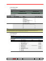
3.2.2.3 Analog output
3.2.2.3.1 Structure
15...8
Bit No.
Word 0
Word 1
7...0
MSB
LSB
Command info - value
(most significant byte of 2 bytes)
Command info - parameter
(most significant byte of 2 bytes)
Command info - value
(least significant byte of 2 bytes)
Command info - parameter
(least significant byte of 2 bytes)
3.2.2.3.2 Details
ANALOG OUTPUT
Number of variables
Number of bytes
2
#
0
Name / Description
(Cyclic) Command info - value
4
1
(Cyclic) Command info - parameter
Range
No command
CB Open
CB Close
CB ResetTrip Reset
Reset Signalling
Reset history measurements
Reset energy countersReset Events log
Restart trigger Datalogger
Stop Datalogger
Start Harmonics Acquisition
Stop Harmonics Acquisition
Don’t care
Only for ‘Start Harmonics Acquisition’ command:
L1
L2
L3
NE
V1
V2
V3
Coding
1
2
3
4
5
7
8
9
10
11
12
0
Length
[bytes] Notes
2
see note 1
see note 2
2
1
2
3
4
5
6
7
Note 1
When you want to send commands, write these 2 AO at the same time, putting a dummy value for the "Command info - parameter"
Note 2
After a 'Start Harmonics Acquisition' command, the new harmonics data are available when the DI 'Waveform available' (# 2) is set.
If the acquisition is temporarly not possible, the DI 'Waveform session status' (# 34) is set.
3.2.2.4 Diagnostics
3.2.2.4.1 Structure
Word No.
Word 0
Bit No.
Byte no. 0
Byte no. 1
7
Diagnostics
present
NOT USED
6
Acyclic command
not executed
NOT USED
5
Wrong parameter
value
NOT USED
4
3
2
Wrong parameter Internal configuration
Device no
number
map error
initialized
Cyclic command not
Cyclic command
RS 485 driver
executed
wrong value
fault
1
Wrong device
connected
Modbus UART
fault
0
No device
communication
Watchdog fault
3.2.2.4.2 Details
DIAGNOSTICS
Number of variables
Number of bytes
ABB SACE
1
2
#
0
1
2
3
4
5
6
7
8
9
10
11
12
13
14
15
Name / Description
No device communication
Wrong device connected
Device not initialized
Internal configuration map error
Wrong parameter number
Wrong parameter value
Command not executed
Diagnostics present
Watchdog fault
Modbus UART fault
RS 485 driver fault
Cyclic command wrong value
Cyclic command not executed
NOT USED
NOT USED
NOT USED
EP010
Coding
Notes
See Table 7.
See Table 7.
See Table 7.
See Table 7.
See Table 7.
See Table 7.
See Table 7.
1 = Diagnostics present
1SDH000510R0001
See Table 7.
See Table 7.
See Table 7.
See Table 7.
See Table 7.
L3116
30/45
45
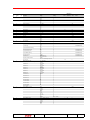
3.2.2.5 Parameters
3.2.2.5.1 Details
Param.
No.
1
length in
bytes
4
Typ
r/w
Parameter
Command info
byte 0-1: command value
byte 2-3; command parameter
2
2
r
Slave ID
3
4
2
2
r
r
SW version
Product Standard reference
5
2
r
Tri/Tetra poles
6
2
r
In (nominal current)
7
2
r
CB type
8
9
10
11
12
8
8
2
2
2
r
r
r
r
r
CB Serial Number 1
CB Serial Number 2
Datalogger max file
Datalogger max address
Datalogger Trigger
13
14
15
16
17
18
19
2
2
2
2
6
6
2
r
r
r
r
r
r
r
Day of Dlogger trigger
Hour & minute of Dlog trigger
Second of Dlog trigger
Millisecond of Dlog trigger
CB name 1
CB name 2
Product execution
20
21
22
8
8
2
r
r
r
Relay Serial Number 1
Relay Serial Number 2
Unit configuration
0:
Rc range (SW version < 2.00)
not used (SW version >= 2.00)
1: Local Bus Unit
2: VT
3: NeutralProtection
4: PowerDir
5: NeutralVoltage
6: Operating mode
23
2
r
ABB SACE
7-15: not used
Language
Units
Multiplier for
Range
Default
(see note 1) value
Range
Coding
No command
0
0
CB Open
CB Close
CB Reset
Trip Reset
Reset Signalling
Reset history measurements
Reset energy counters
Reset Events log
Restart trigger Datalogger
Stop Datalogger
Start Harmonics Acquisition
Stop Harmonics Acquisition
Don’t care
Only for ‘Start Harmonics Acquisition’
command:
L1
L2
L3
NE
V1
V2
V3
“0x51 (PR122)
0x52 (PR123)
0x55 (PR332)
0x56 (PR333)”
MM.mm
IEC
UL1066
UL489
3 poles
4 poles
2 poles
250
400
630
800
1000
1250
1600
2000
2500
3200
4000
5000
6300
PR122/3: See table 9
PR332/3: See table 10
1
2
3
4
5
6
7
8
9
10
11
12
0
0
MSB = MM, LSB = mm
0
1
2
0
1
2
IEC
‘UL 489’ PR332/3 only
3 poles
‘2 poles’ PR332/3 only
A
250
see Note 2
see Note 2
0
0
None
0
1
2
3
4
h.min
s
ms
{0 … 59}
{0 … 999}
1 byte for character (ASCII)
1 byte for character (ASCII)
0
1
2
3
1 byte for character (ASCII)
1 byte for character (ASCII)
LI
LSI
LSIG
LSIRc
Rc range 0.3…3[A] (Idn = 1A)
Rc range 3…30[A] (Idn = 10A)
0
1
Absent
Present
Absent
Present
OFF
ON
Top
Bottom
Absent
Present
Local
Remote
0
1
0
1
0
1
0
1
0
1
0
1
ENG
ITA
FRA
GER
SPA
0
1
2
3
4
EP010
see note 2 in sheet
‘Analog outputs’
1
2
3
4
5
6
7
1 byte for character (ASCII)
1 byte for character (ASCII)
{0 … 3}
{0 … 65535}
None (free running)
Any Alarm
L Timing
Any Trip
Custom
Number of days from 31/12/1999
Notes
1SDH000510R0001
see Note 2
see Note 2
LI
see Note 2
see Note 2
English
L3116
31/45
45
Param.
No.
24
length in
bytes
2
Typ
r
Parameter
Neutral selection
25
2
r
Ext. ground toroid
26
27
2
2
r
r
Nominal voltage Un
VT secondary voltage
28
2
r
Net Frequency
29
2
r
Plant Configuration
30
31
2
2
r
r
Slave Address
Addressing Type
32
2
r
Baud rate
33
2
r
Protocol Type
34
2
r
Ext Toroid Type
35
2
r
Configuration
0: Parameter Set
1: Dual Setting
2: Harmonic Distorsion Warning
3: Phase Rotation Warning
4: Phase Rotation Cycle
5: CosFi Module Warning
6: Dualset CB Close
7: Dualset Vaux
8: Dualset Local Bus disable
36
37
2
2
r
r
9-15: not used
Measurement store time
Loc Bus Relais Unit Contact config
0: Relè K51/1
1: Relè K51/2
2: Relè K51/3
3: Relè K51/4
4: Relè K51/6
5: Relè K51/7
6: Relè K51/8
7: Contact K51/1
8: Contact K51/2
9: Contact K51/3
10: Contact K51/4
11: Contact K51/6
12: Contact K51/7
13: Contact K51/8
38
2
r
14-15: not used
Loc Bus Relais 1 Function
39
40
2
2
r
r
Loc Bus Relais 1 Delay
Loc Bus Relais 2 Function
ABB SACE
Range
50%
100%
150%
200%
100
250
400
800
See table 11
100
110
115
120
200
230
50
60
3P
3P+N
{1 … 247}
Standard
ABB
9600
19200
E,8,1
O,8,1
N,8,2
N,8,1
None
Source Ground Return
Rc
Coding
0
1
2
3
0
1
2
3
0
0
1
2
3
4
5
0
1
0
1
Set A
Set B
OFF
ON
OFF
ON
OFF
ON
123
321
OFF
ON
Disable
Set B on CB close
Disable
Set B on Vaux OFF
Disable
Set B on Local Bus Digital Input ON
0
1
0
1
0
1
0
1
0
1
0
1
0
1
0
1
0
1
Units
Multiplier for
Range
Default
(see note 1) value
1
A
100
V
100
100
Hz
Notes
50
3P
247
Standard
0
1
0
1
0
1
2
3
0
1
2
19200
E,8,1
None
PR123/PR333 only
PR123/PR333 only
PR123/PR333 only
PR123/PR333 only
PR123/PR333 only
PR123/PR333 only
PR123/PR333 only
min
5
{5 ... 120}, step 5
Not Latched
Latched
Not Latched
Latched
Not Latched
Latched
Not Latched
Latched
Not Latched
Latched
Not Latched
Latched
Not Latched
Latched
NO
NC
NO
NC
NO
NC
NO
NC
NO
NC
NO
NC
NO
NC
0
1
0
1
0
1
0
1
0
1
0
1
0
1
0
1
0
1
0
1
0
1
0
1
0
1
0
1
None
L prealarm
L timing
S timing
L trip
S trip
I trip
G trip |
Any trip
Any Alarm
LC1
LC2
Custom
{0.00 ... 100.00}, step 0.01
None
L prealarm
L timing
S timing
L trip
S trip
I trip
0
1
2
3
4
5
6
7
8
9
10
11
{256 … 65535}
EP010
None
s
0
1
2
3
4
5
6
1SDH000510R0001
100
0
None
L3116
32/45
45
Param.
No.
length in
bytes
Typ
Parameter
41
42
2
2
r
r
Loc Bus Relais 2 Delay
Loc Bus Relais 3 Function
43
44
2
2
r
r
Loc Bus Relais 3 Delay
Loc Bus Relais 4 Function
45
46
2
2
r
r
Loc Bus Relais 4 Delay
Loc Bus Relais 6 Function
47
48
2
2
r
r
Loc Bus Relais 6 Delay
Loc Bus Relais 7 Function
49
50
2
2
r
r
Loc Bus Relais 7 Delay
Loc Bus Relais 8 Function
51
52
2
2
r
r
Loc Bus Relais 8 Delay
P Relays Contact config
0: Relay P1
1: Relay P2
2: Relay P3
3: Relay P4
4: Contact P1
5: Contact P2
6: Contact P3
7: Contact P4
53
2
r
ABB SACE
8-15: not used
P1 Function
Range
G trip |
Any trip
Any Alarm
LC1
LC2
Custom
{0.00 ... 100.00}, step 0.01
None
L prealarm
L timing
S timing
L trip
S trip
I trip
G trip |
Any trip
Any Alarm
LC1
LC2
Custom
{0.00 ... 100.00}, step 0.01
None
L prealarm
L timing
S timing
L trip
S trip
I trip
G trip |
Any trip
Any Alarm
LC1
LC2
Custom
{0.00 ... 100.00}, step 0.01
None
L prealarm
L timing
S timing
L trip
S trip
I trip
G trip |
Any trip
Any Alarm
LC1
LC2
Custom
{0.00 ... 100.00}, step 0.01
None
L prealarm
L timing
S timing
L trip
S trip
I trip
G trip |
Any trip
Any Alarm
LC1
LC2
Custom
{0.00 ... 100.00}, step 0.01
None
L prealarm
L timing
S timing
L trip
S trip
I trip
G trip |
Any trip
Any Alarm
LC1
LC2
Custom
{0.00 ... 100.00}, step 0.01
Coding
7
8
9
10
11
{256 … 65535}
Not Latched
Latched
Not Latched
Latched
Not Latched
Latched
Not Latched
Latched
NO
NC
NO
NC
NO
NC
NO
NC
0
1
0
1
0
1
0
1
0
1
0
1
0
1
0
1
None
L prealarm
L timing
S timing
L trip
S trip
I trip
G trip |
0
1
2
3
4
5
6
7
EP010
Units
Multiplier for
Range
Default
(see note 1) value
s
100
0
None
s
100
0
None
s
100
0
None
s
100
0
None
s
100
0
None
s
100
0
0
1
2
3
4
5
6
7
8
9
10
11
{256 … 65535}
0
1
2
3
4
5
6
7
8
9
10
11
{256 … 65535}
0
1
2
3
4
5
6
7
8
9
10
11
{256 … 65535}
0
1
2
3
4
5
6
7
8
9
10
11
{256 … 65535}
0
1
2
3
4
5
6
7
8
9
10
11
{256 … 65535}
1SDH000510R0001
Notes
None
L3116
33/45
45
Param.
No.
length in
bytes
Typ
Parameter
54
55
2
2
r
r
P1 Delay
P2 Function
56
57
2
2
r
r
P2 Delay
P3 Function
58
59
2
2
r
r
P3 Delay
P4 Function
60
61
2
2
r
r
P4 Delay
Programmable Input config
62
2
r
Programmable Input Function
63
64
2
2
r
r
Programmable Input Delay
Data Logger Config
65
2
r
Data Logger Trigger Type
66
67
2
2
r
r
Data Logger Stop Delay
Data Logger Frequency
68
69
70
71
72
73
74
75
76
2
6
4
6
4
2
2
2
2
r
r
r
r
r
r
r
r
r
CosFi Module Threshold
CB TAG name 1
CB TAG name 2
User data 1
User data 2
Dual set CB close time
Date of installation CB
Date of last maint CB
Prot L configuration
0-3: not used
4: Thermal mem
77
2
r
78
79
80
81
82
2
2
2
2
2
r
r
r
r
r
5-15: not used
Prot L curve type
Prot L threshold
Prot L time
Prot L threshold IEC255
Prot L time IEC255
Prot S configuration
0: Prot enable/disable
1: not used
2: Start Up Th
3: Zone sel
4: Thermal mem
Range
Any trip
Any Alarm
LC1
LC2
Custom
{0.00 ... 100.00}, step 0.01
None
L prealarm
L timing
S timing
L trip
S trip
I trip
G trip |
Any trip
Any Alarm
LC1
LC2
Custom
{0.00 ... 100.00}, step 0.01
None
L prealarm
L timing
S timing
L trip
S trip
I trip
G trip |
Any trip
Any Alarm
LC1
LC2
Custom
{0.00 ... 100.00}, step 0.01
None
L prealarm
L timing
S timing
L trip
S trip
I trip
G trip |
Any trip
Any Alarm
LC1
LC2
Custom
{0.00 ... 100.00}, step 0.01
Active High
Coding
8
9
10
11
{256 … 65535}
Units
s
Multiplier for
Range
Default
(see note 1) value
100
0
1
2
3
4
5
6
7
8
9
10
11
{256 … 65535}
No PR332/3
100
0
None
No PR332/3
No PR332/3
s
100
0
None
No PR332/3
No PR332/3
s
100
0
Active
High
No PR332/3
No PR332/3
Generic
No PR332/3
0
OFF
No PR332/3
0
1
2
3
4
5
6
7
8
9
10
11
{256 … 65535}
0
1
0
1
2
3
4
5
6
s
100
0
1
0
1
2
3
{256 … 65535}
0
1
2
3
0
None
s
0
1
2
3
4
5
6
7
8
9
10
11
{256 … 65535}
Active Low
Generic
External TRIP
Trip reset
Set B (PR123 only)
Dial Local |
Reset Signalling Module
Energy reset”
{0.00 ... 100.00}, step 0.01
OFF
ON
None (free running)
Any Alarm
L Timing
Any Trip
Custom
{0.00 ... 10.00}, step 0.01
600
1200
2400
4800
{0.50 ... 0.95}, step 0.01
None
s
Hz
100
0
600
100
0.5
100
0.20
1 byte for character (ASCII)
1 byte for character (ASCII)
1 byte for character (ASCII)
1 byte for character (ASCII)
{0.20 ... 50.00], step 0.10
Number of days from 31/12/1999
Number of days from 31/12/1999
s
OFF
ON
0
1
I2t = k
0,14/(i0.02-1)
13,5*b/(i-1)
80*b/(i2-1)
{0.40 ... 1.00}, step 0.01
{3 ... 144}, step 3
{0.40 ... 1.00}, step 0.01
{3 ... 144}, step 3
0
1
2
3
Disable
Enable
0
1
OFF
ON
OFF
ON
OFF
ON
0
1
0
1
0
1
Notes
PR123/PR333 only
see Note 2
see Note 2
see Note 2
see Note 2
PR123/PR333 only
I2t = k1
In
s
In
s
100
100
100
100
0.4
3
0.4
3
5-15: not used
ABB SACE
EP010
1SDH000510R0001
L3116
34/45
45
Param.
No.
83
length in
bytes
2
Typ
r
Parameter
Prot S curve type
84
85
86
87
88
89
2
2
2
2
2
2
r
r
r
r
r
r
Prot S threshold T=k/I2
Prot S time T=k/I2
Prot S threshold T=k
Prot S time T=k
Prot S start up threshold
Prot S start up time
90
91
2
2
r
r
Prot S zone selectivity time
Prot S2 configuration
0: Prot enable/disable
1: not used
2: Start Up Th
3: Zone sel
92
93
94
95
2
2
2
2
r
r
r
r
96
97
2
2
r
r
4-15: not used
Prot S2 threshold T=k
Prot S2 time T=k
Prot S2 start up threshold
Prot S2 start up time
Prot S2 zone selectivity time
Prot D configuration
0: Prot enable/disable
1: not used
2: Start Up Th
3: Zone sel
98
99
100
101
102
2
2
2
2
2
r
r
r
r
r
103
104
2
2
r
r
4-15: not used
Prot D threshold
Prot D time Forward
Prot D time Backward
Prot D start up threshold
Prot D start up time
Prot D zone selectivity time
Prot I configuration
0: Prot enable/disable
1: not used
2: Start Up Th
105
106
107
2
2
2
r
r
r
108
2
r
3-15: not used
Prot I threshold
Prot I start up threshold
Prot I start up time
Prot G configuration
0: Prot enable/disable
1: not used
2: Start Up Th
3: Zone sel
109
2
r
4-15: not used
Prot G curve type
110
111
112
113
114
115
2
2
2
2
2
2
r
r
r
r
r
r
Prot G threshold T=k/I2
Prot G time T=k/I2
Prot G threshold T=k
Prot G time T=k
Prot G start up threshold
Prot G start up time
116
117
2
2
r
r
Prot G zone selectivity time
Prot Ext G configuration
0: Prot enable/disable
1: not used
2: Start Up Th
3: Zone sel
118
2
r
4-15: not used
Prot Ext G curve type
119
2
r
Prot Ext G threshold T=k/I2
120
121
2
2
r
r
Prot Ext G time T=k/I2
Prot Ext G threshold T=k
122
2
r
Prot Ext G time T=k
ABB SACE
Range
Coding
T=k
0
I2t = k
1
{0.6 ... 10.0}, step 0.1
{0.05 … 0.8}, step 0.01
{0.6 ... 10.0}, step 0.1
{0.05 … 0.8}, step 0.01
{0.6 ... 10.0}, step 0.1
{0.10 ... 1.50}, step 0.01 (SW version <
1.10)
{0.10 ... 30.00}, step 0.01 (SW version
>= 1.10)
{0.04 ... 0.20}, step 0.01
Disable
Enable
0
1
OFF
ON
OFF
ON
“OFF
0
1
0
1
{0.6 ... 10.0}, step 0.1
{0.05 … 0.8}, step 0.01
{0.6 ... 10.0}, step 0.1
{0.10 ... 1.50}, step 0.01 (SW version <
1.10)
{0.10 ... 30.00}, step 0.01 (SW version
>= 1.10)
{0.04 ... 0.20}, step 0.01
Disable
Enable
0
1
OFF
ON
OFF
ON
0
1
0
1
{0.6 ... 10.0}, step 0.1
{0.2 … 0.8}, step 0.01
{0.2 … 0.8}, step 0.01
{0.6 ... 10.0}, step 0.1
{0.10 ... 1.50}, step 0.01 (SW version <
1.10)
{0.10 ... 30.00}, step 0.01 (SW version
>= 1.10)
{0.13 ... 0.50}, step 0.01
Disable
Enable
0
1
OFF
ON
0
1
{1.5 ... 15}, step 0.1
{1.5 ... 15}, step 0.1
{0.10 ... 1.50}, step 0.01 (SW version <
1.10)
{0.10 ... 30.00}, step 0.01 (SW version
>= 1.10)
Disable
Enable
0
1
OFF
ON
OFF
ON
0
1
0
1
T=k
0
I2t = k
1
{0.20 ... 1.00}, step 0.02
{0.10 … 1.00}, step 0.05
{0.20 ... 1.00}, step 0.02
{0.10 … 1.00}, step 0.05
{0.20 ... 1.00}, step 0.02
{0.10 ... 1.50}, step 0.01 (SW version <
1.10)
{0.10 ... 30.00}, step 0.01 (SW version
>= 1.10)
{0.04 ... 0.20}, step 0.01
Disable
Enable
0
1
OFF
ON
OFF
ON
0
1
0
1
T=k
I2t = k
{0.20 ... 1.00}, step 0.02 (SW version <
1.10)
{0.10 ... 1.00}, step 0.02 (SW version
>= 1.10)
{0.10 … 1.00}, step 0.05
“{0.20 ... 1.00}, step 0.02 (SW version
< 1.10)
{0.10 ... 1.00}, step 0.02 (SW version
>= 1.10)”
{0.10 … 1.00}, step 0.05
EP010
1SDH000510R0001
Units
Multiplier for
Range
Default
(see note 1) value
T=k
In
s
In
s
In
s
100
100
100
100
100
100
0.6
0.05
0.6
0.05
0.6
0.1
s
100
0.04
Notes
PR123/PR333 only
PR123/PR333 only
PR123/PR333 only
PR123/PR333 only
PR123/PR333 only
In
s
In
s
100
100
100
100
0.6
0.05
0.6
0.1
PR123/PR333 only
PR123/PR333 only
PR123/PR333 only
PR123/PR333 only
PR123/PR333 only
s
100
0.04
PR123/PR333 only
In
s
s
In
s
100
100
100
100
100
0.6
0.2
0.2
0.6
0.1
PR123/PR333 only
PR123/PR333 only
PR123/PR333 only
PR123/PR333 only
PR123/PR333 only
s
100
0.13
PR123/PR333 only
In
In
s
100
100
100
1.5
1.5
0.1
In
s
In
s
In
s
100
100
100
100
100
100
0.2
0.1
0.2
0.1
0.2
0.1
s
100
0.04
In
100
0.2
s
In
100
100
0.1
0.2
s
100
0.1
T=k
T=k
L3116
35/45
45
Param.
No.
123
length in
bytes
2
Typ
r
Parameter
Prot Ext G start up threshold
124
2
r
Prot Ext G start up time
125
126
2
2
r
r
Prot Ext G zone selectivity time
Prot U configuration
0: Prot enable/disable
Range
Coding
“{0.20 ... 1.00}, step 0.02 (SW version
< 1.10)
{0.10 ... 1.00}, step 0.02 (SW version
>= 1.10)”
{0.10 ... 1.50}, step 0.01 (SW version <
1.10)
{0.10 ... 30.00}, step 0.01 (SW version
>= 1.10)
{0.04 ... 0.20}, step 0.01
1: Trip enable/disable
2-4: not used
5:
not used (SW version < 1.10)
Current/Voltage selection (SW version >= 1.10)
127
128
129
2
2
2
r
r
r
6-15: not used
Prot U threshold
Prot U time
Prot UV configuration
0: Prot enable/disable
1: Trip enable/disable
130
131
132
2
2
2
r
r
r
2-15: not used
Prot UV threshold
Prot UV time
Prot OV configuration
0: Prot enable/disable
1: Trip enable/disable
133
134
135
2
2
2
r
r
r
2-15: not used
Prot OV threshold
Prot OV time
Prot RV configuration
0: Prot enable/disable
1: Trip enable/disable
136
137
138
2
2
2
r
r
r
2-15: not used
Prot RV threshold
Prot RV time
Prot RP configuration
0: Prot enable/disable
1: Trip enable/disable
139
140
141
2
2
2
r
r
r
2-15: not used
Prot RP threshold
Prot RP time
Prot UF configuration
0: Prot enable/disable
1: Trip enable/disable
142
143
144
2
2
2
r
r
r
2-15: not used
Prot UF threshold
Prot UF time
Prot OF configuration
0: Prot enable/disable
1: Trip enable/disable
145
146
147
148
2
2
2
2
r
r
r
r
2-15: not used
Prot OF threshold
Prot OF time
Prot OT configuration
0: not used
1: Trip enable/disable
2-15: not used
Load control configuration
0: Iw Th enable/disable
1: LC1 Th enable/disable
2: LC2 Th enable/disable
149
150
151
152
2
2
2
2
r
r
r
r
3-15: not used
Warning current Iw
LC1 threshold
LC2 threshold
Prot Rc configuration
0:
Prot enable/disable (SW version < 1.10)
not used (SW version >= 1.10)
1:
Trip enable/disable (SW version < 1.10)
153
2
r
not used (SW version >= 1.10)”
2-15: not used
Prot Rc threshold
154
2
r
Prot Rc time
ABB SACE
Disable
Enable
Disable
Enable
0
1
0
1
Current selection
Voltage selection
0
1
{2 ... 90}, step 1
{0.5 ... 60}, step 0.5
Disable
Enable
Disable
Enable
100
0.04
%
s
100
5
0.5
Un
s
100
100
0.50
0.1
Un
s
100
100
1.05
0.1
Un
s
100
100
0.1
0.5
Pnt
s
100
100
-0.10
0.5
Fn
s
100
100
0.9
0.5
Fn
s
100
100
1.01
0.5
In
%I1
%I1
100
0.30
50
50
0
1
0
1
{1.01 ... 1.10}, step 0.01
{0.5 ... 3.0}, step 0.1
Disable
Enable
0
1
Disable
Enable
Disable
Enable
Disable
Enable
0
1
0
1
0
1
{0.30 ... 10.00}, step 0.05
{50 ... 100}, step 1
{50 ... 100}, step 1
Disable
Enable
0
1
Disable
Enable
0
1
3
5
7
10
20
30
0.06
0
1
2
3
4
5
0
EP010
s
0
1
0
1
{0.90 ... 0.99}, step 0.01
{0.5 ... 3.0}, step 0.1
Disable
Enable
Disable
Enable
0.1
0
1
0
1
{-0.10 ... -0.30}, step -0.02
{0.5 ... 25.0}, step 0.1
Disable
Enable
Disable
Enable
100
0
1
0
1
{0.10 ... 0.40}, step 0.05
{0.5 ... 30.0}, step 0.5
Disable
Enable
Disable
Enable
s
Notes
0
1
0
1
{1.05 ... 1.20}, step 0.01
{0.1 ... 5.0}, step 0.1
Disable
Enable
Disable
Enable
Multiplier for
Range
Default
(see note 1) value
100
0.2
0
1
0
1
{0.50 ... 0.95}, step 0.01
{0.1 ... 5.0}, step 0.1
Disable
Enable
Disable
Enable
Units
In
1SDH000510R0001
A
3
s
0.06
L3116
36/45
45
Param.
No.
155
length in
bytes
2
Typ
r
156
2
r
157
158
159
160
161
2
2
2
2
2
r
r
r
r
r
Parameter
Prot L configuration
0-3: not used
4: Thermal mem
5-15: not used
Prot L curve type
Prot L threshold
Prot L time
Prot L threshold IEC255
Prot L time IEC255
Prot S configuration
0: Prot enable/disable
1: not used
2: Start Up Th
3: Zone sel
4: Thermal mem
162
2
r
5-15: not used
Prot S curve type
163
164
165
166
167
168
2
2
2
2
2
2
r
r
r
r
r
r
Prot S threshold T=k/I2
Prot S time T=k/I2
Prot S threshold T=k
Prot S time T=k
Prot S start up threshold
Prot S start up time
169
170
2
2
r
r
Prot S zone selectivity time
Prot S2 configuration
0: Prot enable/disable
1: not used
2: Start Up Th
3: Zone sel
171
172
173
174
2
2
2
2
r
r
r
r
175
176
2
2
r
r
4: Thermal mem
5-15: not used
Prot S2 threshold T=k
Prot S2 time T=k
Prot S2 start up threshold
Prot S2 start up time
Prot S2 zone selectivity time
Prot D configuration
0: Prot enable/disable
1: not used
2: Start Up Th
3: Zone sel
177
178
179
180
181
2
2
2
2
2
r
r
r
r
r
182
183
2
2
r
r
4: Thermal mem
5-15: not used
Prot D threshold
Prot D time Forward
Prot D time Backward
Prot D start up threshold
Prot D start up time
Prot D zone selectivity time
Prot I configuration
0: Prot enable/disable
1: not used
2: Start Up Th
184
185
186
2
2
2
r
r
r
187
2
r
3-15: not used
Prot I threshold
Prot I start up threshold
Prot I start up time
Prot G configuration
0: Prot enable/disable
1: Trip enable/disable
2: Start Up Th
ABB SACE
Range
0.10
0.20
0.30
0.40
0.50
0.80
Coding
1
2
3
4
5
6
if SW version < 1.10, also:
1.00
3.00
4.80
if SW version < 1.10 also:
7
8
9
OFF
ON
0
1
I2t = k
0,14/(i0.02-1)
13,5*b/(i-1)
80*b/(i2-1)
{0.40 ... 1.00}, step 0.01
{3 ... 144}, step 3
{0.40 ... 1.00}, step 0.01
{3 ... 144}, step 3
0
1
2
3
Disable
Enable
0
1
OFF
ON
OFF
ON
OFF
ON
0
1
0
1
0
1
Disable
Enable
0
1
OFF
ON
OFF
ON
OFF
0
1
0
1
0
{0.6 ... 10.0}, step 0.1
{0.05 … 0.8}, step 0.01
{0.6 ... 10.0}, step 0.1
{0.10 ... 1.50}, step 0.01 (SW version <
1.10)
{0.10 ... 30.00}, step 0.01 (SW version
>= 1.10)
{0.04 ... 0.20}, step 0.01
Disable
Enable
I2t = k1
100
100
100
100
0.4
3
0.4
3
Disable
Enable
0
1
ON
OFF
1
0
{1.5 ... 15}, step 0.1
{1.5 ... 15}, step 0.1
{0.10 ... 1.50}, step 0.01 (SW version <
1.10)
{0.10 ... 30.00}, step 0.01 (SW version
>= 1.10)
PR123/PR333 only
PR123/PR333 only
PR123/PR333 only
PR123/PR333 only
PR123/PR333 only
PR123/PR333 only
PR123/PR333 only
T=k
PR123/PR333 only
PR123/PR333 only
In
s
In
s
In
s
100
100
100
100
100
100
0.6
0.05
0.6
0.05
0.6
0.1
PR123/PR333 only
PR123/PR333 only
PR123/PR333 only
PR123/PR333 only
PR123/PR333 only
PR123/PR333 only
s
100
0.04
PR123/PR333 only
PR123/PR333 only
PR123/PR333 only
PR123/PR333 only
PR123/PR333 only
PR123/PR333 only
In
s
In
s
100
100
100
100
0.6
0.05
0.6
0.1
s
100
0.04
PR123/PR333 only
PR123/PR333 only
PR123/PR333 only
PR123/PR333 only
PR123/PR333 only
PR123/PR333 only
PR123/PR333 only
PR123/PR333 only
PR123/PR333 only
PR123/PR333 only
In
s
s
In
s
100
100
100
100
100
0.6
0.2
0.2
0.6
0.1
s
100
0.13
PR123/PR333 only
PR123/PR333 only
PR123/PR333 only
PR123/PR333 only
PR123/PR333 only
PR123/PR333 only
PR123/PR333 only
PR123/PR333 only
PR123/PR333 only
PR123/PR333 only
PR123/PR333 only
PR123/PR333 only
In
In
s
100
100
100
1.5
1.5
0.1
PR123/PR333 only
PR123/PR333 only
PR123/PR333 only
PR123/PR333 only
PR123/PR333 only
PR123/PR333 only
0
1
0
1
1
1SDH000510R0001
PR123/PR333 only
PR123/PR333 only
PR123/PR333 only
0
1
0
1
0
{0.6 ... 10.0}, step 0.1
{0.2 … 0.8}, step 0.01
{0.2 … 0.8}, step 0.01
{0.6 ... 10.0}, step 0.1
{0.10 ... 1.50}, step 0.01 (SW version <
1.10)
{0.10 ... 30.00}, step 0.01 (SW version
>= 1.10)”
{0.13 ... 0.50}, step 0.01
Notes
PR123/PR333 only
PR123/PR333 only
0
1
OFF
ON
OFF
ON
OFF
EP010
Multiplier for
Range
Default
(see note 1) value
PR123/PR333 only
PR123/PR333 only
PR123/PR333 only
In
s
In
s
T=k
0
I2t = k
1
{0.6 ... 10.0}, step 0.1
{0.05 … 0.8}, step 0.01
{0.6 ... 10.0}, step 0.1
{0.05 … 0.8}, step 0.01
{0.6 ... 10.0}, step 0.1
{0.10 ... 1.50}, step 0.01 (SW version <
1.10)
{0.10 ... 30.00}, step 0.01 (SW version
>= 1.10)
{0.04 ... 0.20}, step 0.01
Disable
Enable
Disable
Enable
ON
Units
PR123/PR333 only
PR123/PR333 only
L3116
37/45
45
Param.
No.
length in
bytes
Typ
Parameter
Range
OFF
ON
OFF
3: Zone sel
188
2
r
4-15: not used
Prot G curve type
189
190
191
192
193
194
2
2
2
2
2
2
r
r
r
r
r
r
Prot G threshold T=k/I2
Prot G time T=k/I2
Prot G threshold T=k
Prot G time T=k
Prot G start up threshold
Prot G start up time
195
196
2
2
r
r
Prot G zone selectivity time
Prot Ext G configuration
0: Prot enable/disable
T=k
0
I2t = k
1
{0.20 ... 1.00}, step 0.02
{0.10 … 1.00}, step 0.05
{0.20 ... 1.00}, step 0.02
{0.10 … 1.00}, step 0.05
{0.20 ... 1.00}, step 0.02
{0.10 ... 1.50}, step 0.01 (SW version <
1.10)
{0.10 ... 30.00}, step 0.01 (SW version
>= 1.10)
{0.04 ... 0.20}, step 0.01
Disable
Enable
Disable
Enable
ON
OFF
ON
OFF
1: Trip enable/disable
2: Start Up Th
3: Zone sel
197
2
r
4-15: not used
Prot Ext G curve type
198
2
r
Prot Ext G threshold T=k/I2
199
200
2
2
r
r
Prot Ext G time T=k/I2
Prot Ext G threshold T=k
201
202
2
2
r
r
Prot Ext G time T=k
Prot Ext G start up threshold
203
2
r
Prot Ext G start up time
204
205
2
2
r
r
Prot Ext G zone selectivity time
Prot U configuration
0: Prot enable/disable
Disable
Enable
Disable
Enable
2-4: not used
5:
not used (SW version < 1.10)
Current/Voltage selection (SW version >= 1.10)
206
207
208
2
2
2
r
r
r
1: Trip enable/disable
209
210
211
2
2
2
r
r
r
2-15: not used
Prot UV threshold
Prot UV time
Prot OV configuration
0: Prot enable/disable
1: Trip enable/disable
212
213
214
2
2
2
r
r
r
2-15: not used
Prot OV threshold
Prot OV time
Prot RV configuration
0: Prot enable/disable
1: Trip enable/disable
215
216
217
2
2
2
r
r
r
2-15: not used
Prot RV threshold
Prot RV time
Prot RP configuration
0: Prot enable/disable
1: Trip enable/disable
218
219
220
2
2
2
r
r
r
2-15: not used
Prot RP threshold
Prot RP time
Prot UF configuration
0: Prot enable/disable
1: Trip enable/disable
221
222
223
2
2
2
r
r
r
ABB SACE
2-15: not used
Prot UF threshold
Prot UF time
Prot OF configuration
0: Prot enable/disable
Current selection
Voltage selection
Disable
Enable
Disable
Enable
EP010
0.2
0.1
0.2
0.1
0.2
0.1
PR123/PR333 only
PR123/PR333 only
PR123/PR333 only
PR123/PR333 only
PR123/PR333 only
PR123/PR333 only
s
100
0.04
PR123/PR333 only
PR123/PR333 only
PR123/PR333 only
PR123/PR333 only
PR123/PR333 only
T=k
PR123/PR333 only
PR123/PR333 only
In
100
0.2
PR123/PR333 only
s
In
100
100
0.1
0.2
PR123/PR333 only
PR123/PR333 only
s
In
100
100
0.1
0.2
PR123/PR333 only
PR123/PR333 only
s
100
0.1
PR123/PR333 only
s
100
0.04
PR123/PR333 only
PR123/PR333 only
PR123/PR333 only
PR123/PR333 only
PR123/PR333 only
PR123/PR333 only
PR123/PR333 only
PR123/PR333 only
100
5
0.5
100
100
0.50
0.1
PR123/PR333 only
PR123/PR333 only
PR123/PR333 only
PR123/PR333 only
PR123/PR333 only
PR123/PR333 only
Un
s
100
100
1.05
0.1
0
1
0
1
PR123/PR333 only
PR123/PR333 only
PR123/PR333 only
PR123/PR333 only
PR123/PR333 only
PR123/PR333 only
Un
s
100
100
0.1
0.5
0
1
0
1
PR123/PR333 only
PR123/PR333 only
PR123/PR333 only
PR123/PR333 only
PR123/PR333 only
PR123/PR333 only
Pnt
s
100
100
-0.10
0.5
0
1
0
1
PR123/PR333 only
PR123/PR333 only
PR123/PR333 only
PR123/PR333 only
PR123/PR333 only
PR123/PR333 only
Fn
s
100
100
0.9
0.5
0
1
1SDH000510R0001
PR123/PR333 only
PR123/PR333 only
PR123/PR333 only
PR123/PR333 only
PR123/PR333 only
PR123/PR333 only
0
1
0
1
{0.90 ... 0.99}, step 0.01
{0.5 ... 3.0}, step 0.1
Disable
Enable
100
100
100
100
100
100
Un
s
{-0.10 ... -0.30}, step -0.02
{0.5 ... 25.0}, step 0.1
Disable
Enable
Disable
Enable
T=k
In
s
In
s
In
s
0
1
0
1
{0.10 ... 0.40}, step 0.05
{0.5 ... 30.0}, step 0.5
Disable
Enable
Disable
Enable
PR123/PR333 only
%
s
{1.05 ... 1.20}, step 0.01
{0.1 ... 5.0}, step 0.1
Notes
PR123/PR333 only
PR123/PR333 only
0
1
{0.50 ... 0.95}, step 0.01
{0.1 ... 5.0}, step 0.1
Disable
Enable
Disable
Enable
Multiplier for
Range
Default
(see note 1) value
0
1
0
1
{2 ... 90}, step 1
{0.5 ... 60}, step 0.5
Disable
Enable
Disable
Enable
Units
0
1
0
1
1
0
1
0
T=k
I2t = k
{0.20 ... 1.00}, step 0.02 (SW version <
1.10)
{0.10 ... 1.00}, step 0.02 (SW version
>= 1.10)
{0.10 … 1.00}, step 0.05
{0.20 ... 1.00}, step 0.02 (SW version <
1.10)
{0.10 ... 1.00}, step 0.02 (SW version
>= 1.10)
{0.10 … 1.00}, step 0.05
{0.20 ... 1.00}, step 0.02 (SW version <
1.10)
{0.10 ... 1.00}, step 0.02 (SW version
>= 1.10)
{0.10 ... 1.50}, step 0.01 (SW version <
1.10)
{0.10 ... 30.00}, step 0.01 (SW version
>= 1.10)
{0.04 ... 0.20}, step 0.01
1: Trip enable/disable
6-15: not used
Prot U threshold
Prot U time
Prot UV configuration
0: Prot enable/disable
Coding
0
1
0
L3116
PR123/PR333 only
PR123/PR333 only
PR123/PR333 only
PR123/PR333 only
PR123/PR333 only
38/45
45
Param.
No.
length in
bytes
Typ
224
225
226
2
2
2
r
r
r
227
2
r
Parameter
1: Trip enable/disable
2-15: not used
Prot OF threshold
Prot OF time
Prot OT configuration
0: not used
1: Trip enable/disable
2-15: not used
Load control configuration
0: Iw Th enable/disable
1: LC1 Th enable/disable
2: LC2 Th enable/disable
228
229
230
231
2
2
2
2
r
r
r
r
3-15: not used
Warning current Iw
LC1 threshold
LC2 threshold
Prot Rc configuration
0:
Prot enable/disable (SW version < 1.10)
not used (SW version >= 1.10)”
1:
Trip enable/disable (SW version < 1.10)
232
2
r
not used (SW version >= 1.10)”
2-15: not used
Prot Rc threshold
233
2
r
Prot Rc time
234
235
2
2
r
r
Total power factor
Frequency
236
2
r
V1 line to neutral voltage
237
2
r
V2 line to neutral voltage
238
2
r
V3 line to neutral voltage
239
4
r
Total Active Energy
240
4
r
Total Reactive Energy
241
4
r
Total Apparent Energy
242
4
r
Total Apparent Power
243
244
245
246
247
248
249
250
251
252
253
254
255
2
2
2
2
2
2
2
2
2
2
2
2
2
r
r
r
r
r
r
r
r
r
r
r
r
r
Total Harmonic Distortion (THD)
3rd Harmonic ratio
5th Harmonic ratio
7th Harmonic ratio
9th Harmonic ratio
11th Harmonic ratio
13th Harmonic ratio
15th Harmonic ratio
17th Harmonic ratio
19th Harmonic ratio
21st Harmonic ratio
23rd Harmonic ratio
25th Harmonic ratio
Range
Disable
Enable
Coding
0
1
{1.01 ... 1.10}, step 0.01
{0.5 ... 3.0}, step 0.1
Units
Fn
s
Disable
Enable
0
1
Disable
Enable
Disable
Enable
Disable
Enable
0
1
0
1
0
1
{0.30 ... 10.00}, step 0.05
{50 ... 100}, step 1
{50 ... 100}, step 1
0
1
Disable
Enable
0
1
3
5
7
10
20
30
0.06
0.10
0.20
0.30
0.40
0.50
0.80
0
1
2
3
4
5
0
1
2
3
4
5
6
if SW version < 1.10, also:
1.00
3.00
4.80”
signed
not available
F < FMIN --> FMIN
F > FMAX --> FMAX
not available
V < 5.7 V
V > 922 V
not available
V < 5.7 V
V > 922 V
not available
V < 5.7 V
V > 922 V
E < -231
E > 231-1
E < -231
E > 231-1
E < -231
E > 231-1
not available
abs(P) < 0.5In * 5.7 V
P >= 16In*922 V
P <= -16In*922V
if SW version < 1.10 also:
7
8
9
215-1
216-1
216-1
0
9220
216-1
0
9220
216-1
0
9220
231
231-1
231
231-1
231
231-1
231-1
0
16In*9220
-16In*9220
100
100
1.01
0.5
Notes
PR123/PR333 only
PR123/PR333 only
PR123/PR333 only
PR123/PR333 only
PR123/PR333 only
PR123/PR333 only
PR123/PR333 only
PR123/PR333 only
PR123/PR333 only
PR123/PR333 only
PR123/PR333 only
PR123/PR333 only
In
%I1
%I1
Disable
Enable
Multiplier for
Range
Default
(see note 1) value
100
0.30
50
50
PR123/PR333 only
PR123/PR333 only
PR123/PR333 only
PR123/PR333 only
PR123/PR333 only
PR123/PR333 only
PR123/PR333 only
PR123/PR333 only
PR123/PR333 only
A
3
PR123/PR333 only
PR123/PR333 only
PR123/PR333 only
s
0.06
PR123/PR333 only
Hz
100
10
V
10
V
10
V
10
kWh
kVARh
kVAh
kVA
10
[‰]
[‰]
[‰]
[‰]
[‰]
[‰]
[‰]
[‰]
[‰]
[‰]
[‰]
[‰]
[‰]
Note 1:
If the Multiplier is present, divede the data got from the device (Coding) by this multipler to get actual value (Range).
Note 2:
FOR DEVICENET ONLY: bytes inside every word are swapped. To get the right values, they have to be swapped. Moreover, the information is
truncated to 4 bytes.
Note 3
ABB SACE
EP010
1SDH000510R0001
L3116
39/45
45
Param.
No.
length in
bytes
Typ
Parameter
Range
Coding
Units
Multiplier for
Range
Default
(see note 1) value
Notes
FOR DEVICENET: bytes order is according to the Intel format
(little endian).
FOR PROFIBUS: bytes order is according to the Motorola format
(big endian).
Example:
Example:
00
00
00
00
01
00
01
00
01
00
00
00
01
00
00
01
0B
00
00
00
(hex)
(hex)
(hex)
(hex)
(hex)
RIGHT
RIGHT
WRONG
RIGHT (dummy command)
RIGHT (dummy command)
00
00
01
00
00
01
0B
00
00
00
00
00
00
01
00
00
01
00
00
01
(hex)
(hex)
(hex)
(hex)
(hex)
RIGHT
RIGHT
WRONG
RIGHT (dummy command)
RIGHT (dummy command)
Table 9. CB type PR122/3
ABB SACE
Coding
"CB type Pr122/3”
Coding
"CB type Pr122/3”
Coding
"CB type Pr122/3”
Coding
"CB type Pr122/3”
0
1
2
3
4
5
6
7
8
9
10
11
12
13
14
15
16
17
18
19
20
21
22
23
24
25
26
27
28
29
30
31
32
33
34
35
36
37
38
39
40
41
42
43
44
45
46
47
48
49
50
51
52
53
54
55
56
57
58
59
60
61
62
63
64
65
66
67
68
69
E1B800/3P
E1B800/4P
E1B1000/3P
E1B1000/4P
E1B1250/3P
E1B1250/4P
E1B1600/3P
E1B1600/4P
E1N800/3P
E1N800/4P
E1N1000/3P
E1N1000/4P
E1N1250/3P
E1N1250/4P
E1N1600/3P
E1N1600/4P
E2B1600/3P
E2B1600/4P
E2B2000/3P
E2B2000/4P
E2N1000/3P
E2N1000/4P
E2N1250/3P
E2N1250/4P
E2N1600/3P
E2N1600/4P
E2N2000/3P
E2N2000/4P
E2S800/3P
E2S800/4P
E2S1000/3P
E2S1000/4P
E2S1250/3P
E2S1250/4P
E2S1600/3P
E2S1600/4P
E2S2000/3P
E2S2000/4P
E2L1250/3P
E2L1250/4P
E2L1600/3P
E2L1600/4P
E3N2500/3P
E3N2500/4P
E3N3200/3P
E3N3200/4P
E3S1000/3P
E3S1000/4P
E3S1250/3P
E3S1250/4P
E3S1600/3P
E3S1600/4P
E3S2000/3P
E3S2000/4P
E3S2500/3P
E3S2500/4P
E3S3200/3P
E3S3200/4P
E3H800/3P
E3H800/4P
E3H1000/3P
E3H1000/4P
E3H1250/3P
E3H1250/4P
E3H1600/3P
E3H1600/4P
E3H2000/3P
E3H2000/4P
E3H2500/3P
E3H2500/4P
70
71
72
73
74
75
76
77
78
79
80
81
82
83
84
85
86
87
88
89
90
91
92
93
94
95
96
97
98
99
100
101
102
103
104
105
106
107
108
109
110
111
112
113
114
115
116
117
118
119
120
121
122
123
124
125
126
127
128
129
130
131
132
133
134
135
136
137
138
139
E3H3200/3P
E3H3200/4P
E3V800/3P
E3V800/4P
E3V1250/3P
E3V1250/4P
E3V1600/3P
E3V1600/4P
E3V2000/3P
E3V2000/4P
E3V2500/3P
E3V2500/4P
E3V3200/3P
E3V3200/4P
E3L2000/3P
E3L2000/4P
E3L2500/3P
E3L2500/4P
E4S4000/3P
E4S4000/4P
--E4S/f4000/4P
E4H3200/3P
E4H3200/4P
--E4H/f3200/4P
E4H4000/3P
E4H4000/4P
--E4H/f4000/4P
E4V3200/3P
E4V3200/4P
E4V4000/3P
E4V4000/4P
E6H4000/3P
E6H4000/4P
E6H5000/3P
E6H5000/4P
--E6H/f5000/4P
E6H6300/3P
E6H6300/4P
--E6H/f6300/4P
E6V3200/3P
E6V3200/4P
E6V4000/3P
E6V4000/4P
E6V5000/3P
E6V5000/4P
E6V6300/3P
E6V6300/4P
E1B-A800/3P
E1B-A800/4P
E1B-A1200/3P
E1B-A1200/4P
E2B-A1600/3P
E2B-A1600/4P
E2N-A1200/3P
E2N-A1200/4P
E2N-A1600/3P
E2N-A1600/4P
E2S-A1200/3P
E2S-A1200/4P
E2S-A1600/3P
E2S-A1600/4P
E3N-A2000/3P
E3N-A2000/4P
E3N-A2500/3P
E3N-A2500/4P
140
141
142
143
144
145
146
147
148
149
150
151
152
153
154
155
156
157
158
159
160
161
162
163
164
165
166
167
168
169
170
171
172
173
174
175
176
177
178
179
180
181
182
183
184
185
186
187
188
189
190
191
192
193
194
195
196
197
198
199
200
201
202
203
204
205
206
207
208
209
E3S-A1200/3P
E3S-A1200/4P
E3S-A1600/3P
E3S-A1600/4P
E3S-A2000/3P
E3S-A2000/4P
E3S-A2500/3P
E3S-A2500/4P
E3H-A1200/3P
E3H-A1200/4P
E3H-A1600/3P
E3H-A1600/4P
E3H-A2000/3P
E3H-A2000/4P
E3H-A2500/3P
E3H-A2500/4P
E3V-A1200/3P
E3V-A1200/4P
E3V-A1600/3P
E3V-A1600/4P
E3V-A2000/3P
E3V-A2000/4P
E3V-A2500/3P
E3V-A2500/4P
E4S-A3200/3P
E4S-A3200/4P
E4S-A3600/3P
E4S-A3600/4P
E4H-A3200/3P
E4H-A3200/4P
E4H-A3600/3P
E4H-A3600/4P
E4V-A3200/3P
E4V-A3200/4P
E4V-A3600/3P
E4V-A3600/4P
E6H-A4000/3P
E6H-A4000/4P
E6H-A5000/3P
E6H-A5000/4P
E6V-A4000/3P
E6V-A4000/4P
E6V-A5000/3P
E6V-A5000/4P
--E6H/f4000/4P
E1N-A800/3P
E1N-A800/4P
E1N-A1200/3P
E1N-A1200/4P
E2N-A800/3P
E2N-A800/4P
E2S-A800/3P
E2S-A800/4P
E2H-A800/3P
E2H-A800/4P
E2H-A1200/3P
E2H-A1200/4P
E2H-A1600/3P
E2H-A1600/4P
E3S-A800/3P
E3S-A800/4P
E3S-A3200/3P
E3S-A3200/4P
E3H-A800/3P
E3H-A800/4P
E3H-A3200/3P
E3H-A3200/4P
E3V-A800/3P
E3V-A800/4P
210
211
212
213
214
215
216
217
218
219
220
221
222
223
224
225
226
227
228
229
230
231
232
233
234
235
236
237
238
239
E3V-A3200/3P
E3V-A3200/4P
--E4H-A/f3200/4P
--E4H-A/f3600/4P
E4L-A3200/3P
E4L-A3200/4P
E4L-A3600/3P
E4L-A3600/4P
--E6H-A/f4000/4P
--E6H-A/f5000/4P
E6L-A4000/3P
E6L-A4000/4P
E6L-A5000/3P
E6L-A5000/4P
E3L-A800/3P
E3L-A800/4P
E3L-A1200/3P
E3L-A1200/4P
E3L-A1600/3P
E3L-A1600/4P
E3L-A2000/3P
E3L-A2000/4P
E6VL-A4000/3P
E6VL-A4000/4P
E6VL-A5000/3P
E6VL-A5000/4P
EP010
1SDH000510R0001
L3116
40/45
45
Table 10. CB type PR332/3
Coding
0
1
2
3
4
5
6
7
8
9
10
11
12
13
14
15
16
17
18
19
20
21
22
23
24
25
26
27
28
29
30
31
32
33
34
35
“CB type
PR332/3”
T7S800/3P
T7S800/4P
T7S1000/3P
T7S1000/4P
T7S1250/3P
T7S1250/4P
T7S1600/3P
T7S1600/4P
T7H800/3P
T7H800/4P
T7H1000/3P
T7H1000/4P
T7H1250/3P
T7H1250/4P
T7H1600/3P
T7H1600/4P
T7L800/3P
T7L800/4P
T7L1000/3P
T7L1000/4P
T7L1250/3P
T7L1250/4P
T7L1600/3P
T7L1600/4P
T7V800/3P
T7V800/4P
T7V1000/3P
T7V1000/4P
T7V1250/3P
T7V1250/4P
T7S1200/3P
T7S1200/4P
T7H1200/3P
T7H1200/4P
T7L1200/3P
T7L1200/4P
Standard
IEC
IEC
IEC
IEC
IEC
IEC
IEC
IEC
IEC
IEC
IEC
IEC
IEC
IEC
IEC
IEC
IEC
IEC
IEC
IEC
IEC
IEC
IEC
IEC
IEC
IEC
IEC
IEC
IEC
IEC
UL489
UL489
UL489
UL489
UL489
UL489
Coding
36
37
38
39
40
41
42
43
44
45
46
47
48
49
50
51
52
53
54
55
56
57
58
59
60
61
62
63
64
65
66
67
68
69
70
71
“CB type
PR332/3”
X1B630/3P
X1B630/4P
X1B800/3P
X1B800/4P
X1B1000/3P
X1B1000/4P
X1B1250/3P
X1B1250/4P
X1B1600/3P
X1B1600/4P
X1N630/3P
X1N630/4P
X1N800/3P
X1N800/4P
X1N1000/3P
X1N1000/4P
X1N1250/3P
X1N1250/4P
X1N1600/3P
X1N1600/4P
X1L630/3P
X1L630/4P
X1L800/3P
X1L800/4P
X1L1000/3P
X1L1000/4P
X1L1250/3P
X1L1250/4P
X1B800/3P
X1B800/4P
X1B1200/3P
X1B1200/4P
X1N800/3P
X1N800/4P
X1N1200/3P
X1N1200/4P
Standard
IEC
IEC
IEC
IEC
IEC
IEC
IEC
IEC
IEC
IEC
IEC
IEC
IEC
IEC
IEC
IEC
IEC
IEC
IEC
IEC
IEC
IEC
IEC
IEC
IEC
IEC
IEC
IEC
UL1066
UL1066
UL1066
UL1066
UL1066
UL1066
UL1066
UL1066
“CB type
PR332/3”
X1L800/3P
X1L800/4P
X1L1200/3P
X1L1200/4P
X1B800/3P
X1B800/4P
X1B1200/3P
X1B1200/4P
X1B1600/3P
X1B1600/4P
X1N800/3P
X1N800/4P
X1N1200/3P
X1N1200/4P
X1N1600/3P
X1N1600/4P
X1L800/3P
X1L800/4P
X1L1200/3P
X1L1200/4P
X1V800/3P
X1V800/4P
X1V1200/3P
X1V1200/4P
Coding
72
73
74
75
76
77
78
79
80
81
82
83
84
85
86
87
88
89
90
91
92
93
94
95
Standard
UL1066
UL1066
UL1066
UL1066
UL489
UL489
UL489
UL489
UL489
UL489
UL489
UL489
UL489
UL489
UL489
UL489
UL489
UL489
UL489
UL489
UL489
UL489
UL489
UL489
Table 11.
Coding
0
1
2
3
4
5
6
7
Un
100
115
120
190
208
220
230
240
Coding
8
9
10
11
12
13
14
15
Un
277
347
380
400
415
440
480
500
Coding
16
17
18
19
20
21
22
23
Un
550
600
660
690
910
950
1000
1150
3.2.2.5.2 Example: PROFIBUS DP data structure
Data type
Cyclic data
exchange
Group
Example
Quantity/Presentation
Direction
DI = digital input
Status, alarms, trips …
118 single Bits in 15 Bytes
read
AI = analog input
Run-time measures
16 Words
read
DO = digital outout
Not available
-
-
AO = analog output
Commands
2 Words
write
Diagnosis
Faults and warnings
11 single Bits in 1 Word
read
Configuration,
identification
Not available
-
-
Bus specific data
Not available
-
-
Not available
-
-
Device configuration, Protection
parameters ...
233 single parameters of
different lenghts (2, 4, 6 or 8
Bytes)
read/write
Other basic
data transfer Block parameters
Acyclcic data
Single parameters
exchange
Remarks:
Diagnosis.
ABB SACE
The diagnosis telegrams of the PROFIBUS DP slaves start with additional 2 bytes that concern the
number of diagnosis bytes and status of the slave.
EP010
1SDH000510R0001
L3116
41/45
45
Configuration: Modern fieldbuses such as PROFIBUS DP-V0, -V1 and DeviceNet fix the Configuration data using
the appropriate configuration files (e.g. “xxx.GSD”, “xxx.EDS”) and write it automatically into the
FieldBusPlug during power up.
Most of the FieldBusPlug types compare the Configuration data sent by the EP010 with the
Configuration data received from the fieldbus. When the result of the comaprison is ok, parameters
can be downloaded and the operation can start.
The Configuration data set contains the product code.
Additional to the above named data the FieldBusPlug - only the FieldBus-Plug, not the EP010- can
send on request identification data such as vendor name, slave address and data baud rate as
defined in the appropriate FieldBus standard.
Parameters:
Depending on the fieldbus type the parameters can be:
- written as parameter block - only complete block - (e.g. PROFIBUS DP-V0) or
- written and read as single parameters (e.g. PROFIBUS DP-V1, DeviceNet)
3.2.3 Performance data and conditions
Parameters refresh rate
ABB SACE
EP010
max. 20 [s]
1SDH000510R0001
L3116
42/45
45
4. REVISION HISTORY
4.1
Revision a - 06/10/2004
First release for review.
4.2
Revision b - 17/11/2004
First release.
4.3
Revision c - 06/12/2004
4.3.1 Modified
Figure 1: swapped 'A/-' with 'B/+'
Table 2: swapped 'A/-' with 'B/+'
4.4
Revision d - 21/12/2004
4.4.1 Added
Figure 5: added Protective Earth connection.
4.4.2 Modified
Figure 1 and Table 2: changed 'A/-' with 'A' and 'B/+' with 'B'.
4.5
Revision e - 10/02/2005
4.5.1 Added
Par. 3.1: reference to ABB SACE documentation 'GSD file, doc. n. ITSCE-RE1024001'
Par. 3.2: reference to ABB SACE documentation 'GSD file, doc. n. ITSCE-RE1024001'
Table 14: rows 118 and 119 to complete a byte.
ABB SACE
EP010
1SDH000510R0001
L3116
43/45
45
4.5.2 Modified
Par. 3.2.1.1: changed 'Number of bytes: 14' with 'Number of bytes: 15'.
4.6
Revision f - 04/03/2005
4.6.1 Added
Par. 3.1.1: inserted the wiring diagrams.
Par. 3.1.2: inserted Excel file with detailed information available.
Par. 3.1.3: inserted detailed information refresh rate.
Par. 3.2.1: inserted the wiring diagrams.
Par. 3.2.2: inserted Excel file with detailed information available.
Par. 3.2.3: inserted detailed information refresh rate.
4.6.2 Modified
Par. 2.8.5: changed 'Modbus scan rate' with 'Modbus polling rate'. Changed '3000 [ms]' with
'3 [s]'.
Par. 3.1: inserted the right EDS file name.
Par. 3.2: inserted the right EDS file name.
4.6.3 Deleted
Tables 9 - 16.
4.7
Revision g - 24/03/2005
4.7.1 Modified
Par. 3.2: new version of the Excel file. Changed the number of bytes of 'CB TAG Name 1 and
2' and 'User Data 1 and 2'.
4.8
Revision h - 06/10/2005
4.8.1 Added
Par. 3.1: added 'FBP Product Code' information.
Par. 3.2: added 'FBP Product Code' information.
ABB SACE
EP010
1SDH000510R0001
L3116
44/45
45
4.8.2 Modified
General review for orthographic corrections and clarity.
Changed 'field bus plug' references to 'FieldBusPlug' according to FBP manuals.
Par. 2.4.2.1: changed to simplify.
Par. 3.1.2: changed paragraph structure.
Par. 3.2.2: changed paragraph structure.
4.9
Revision i - 25/08/2006
Applicable to SW v02.xx and above.
4.9.1 Added
Par. 2.1: added 'In particular, EP010 acts as a communication gateway between FieldBusPlug and Modbus device.'
Par. 3.2: added PR332/3
4.9.2 Modified
Par. 2.2: title changed from "Device description" to "EP010 description".
Par. 2.4: changed paragraph structure and content.
Par. 3.2.2: changed the embedded Excel file.
4.10
Revision j - 29/01/2007
Applicable to SW v02.xx and above.
4.10.1Modified
Table 7: added two new diagnostics.
Par. 3.1.2: changed the embedded Excel file and headungs order.
Par. 3.2.2: changed the embedded Excel file and headungs order.
ABB SACE
EP010
1SDH000510R0001
L3116
45/45
45