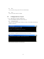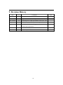
1
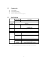
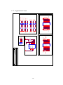
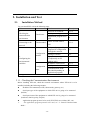
EZL-410 User’s Manual Version 1.6 Sollae Systems Inc. To all residents of the European Union Important environmental information about this product This symbol on this unit or the package indicates that disposal of this unit after its lifecycle could harm the environment. Do not dispose of the unit as unsorted municipal waste; it should be brought to a specialized company for recycling. It is your responsibility to return this unit to your local recycling service. Respect your local environmental regulation. If in doubt, contact your local waste disposal authorities. -2- -Table of Content 1. OVERVIEW ..................................................................................................................... - 5 - 1.1. OVERVIEW ......................................................................................................................- 5 - 1.2. COMPONENTS..................................................................................................................- 6 - 1.3. SPECIFICATIONS ..............................................................................................................- 6 - 1.3.1. Dimension ..................................................................................................................... - 7 - 1.3.2. Pin Configuration.......................................................................................................... - 8 - 1.3.3. Application Circuit ...................................................................................................... - 10 - 1.3.4. Network Interface .........................................................................................................- 11 - 1.3.5. Serial Interface .............................................................................................................- 11 - 2. INSTALLATION AND TEST ....................................................................................... - 12 - 2.1. INSTALLATION METHOD ................................................................................................ - 12 - 2.1.1. Checking the Communication Environment ................................................................ - 12 - 2.1.2. Connecting to the Network .......................................................................................... - 13 - 2.1.3. Configuring the Environmental Variables ................................................................... - 13 - 2.2. TEST.............................................................................................................................. - 13 - 2.2.1. Changing PC IP Address ............................................................................................. - 13 - 2.2.2. Installing EZL-410 ...................................................................................................... - 13 - 2.2.3. Connecting to Serial Port of PC.................................................................................. - 13 - 2.2.4. Communication Test .................................................................................................... - 14 - 3. CONFIGURING ENVIRONMENTAL VARIABLES ................................................ - 15 - 3.1. CONFIGURATION WITH EZCFGMP ................................................................................... - 15 - 3.1.1. Local Search ................................................................................................................ - 15 - 3.1.2. Remote Search ............................................................................................................. - 16 - 3.1.3. The differences between LOCAL SEARCH and REMOTE SEARCH .......................... - 17 - 3.1.4. Configuring with ezcfgmp ........................................................................................... - 18 - 3.2. CONFIGURATION BY CONSOLE ...................................................................................... - 22 - 3.2.1. Entering the Console of EZL-410 ................................................................................ - 22 - 3.2.2. Menu Structure ............................................................................................................ - 23 - 4. THE OPERATION MODE OF EZL-410 .................................................................... - 25 - 4.1. NORMAL COMMUNICATION MODE ...............................................................................- 25 - 4.2. ISP MODE ..................................................................................................................... - 25 - 5. NORMAL COMMUNICATION MODE .................................................................... - 28 - -3- 5.1. T2S ............................................................................................................................... - 28 - 5.1.1. Communication ........................................................................................................... - 28 - 5.1.2. Connection Termination and Keep-Alive Function ..................................................... - 28 - 5.2. ATC .............................................................................................................................. - 29 - 5.3. COD ............................................................................................................................. - 30 - 5.3.1. Communication ........................................................................................................... - 30 - 5.3.2. Connection Termination and Keep-Alive Function ..................................................... - 30 - 5.3.3. Reconnection ............................................................................................................... - 30 - 5.4. U2S............................................................................................................................... - 31 - 6. ATC MODE.................................................................................................................... - 32 - 6.1. OVERVIEW .................................................................................................................... - 32 - 6.1.1. AT command format .................................................................................................... - 32 - 6.2. BASIC AT COMMAND SET (EXAMPLE: ATA, ATD ETC.) ................................................- 32 - 6.3. EXTENDED AT COMMANDS (EXAMPLE: AT+PLIP ETC.) ...............................................- 33 - 6.4. ON-LINE STATE AND COMMAND STATE .........................................................................- 33 - 6.4.1. Changing On-line State to Command State ................................................................. - 33 - 6.4.2. Changing Command State to On-line State ................................................................. - 33 - 6.5. EXAMPLE OF TCP CONNECTION ................................................................................... - 34 - 6.5.1. Example of Active Connection .................................................................................... - 34 - 6.5.2. Example of passive Connection ................................................................................... - 34 - 6.6. EXAMPLE OF TCP DISCONNECTION ..............................................................................- 34 - 6.6.1. Example of active disconnection ................................................................................. - 34 - 6.6.2. Example of passive disconnection ............................................................................... - 35 - 7. TECHNICAL SUPPORT, WARRANTY, AND NOTES ON OPERATION ............. - 36 - 7.1. TECHNICAL SUPPORT ....................................................................................................- 36 - 7.2. WARRANTY .................................................................................................................. - 36 - 7.2.1. Refund ......................................................................................................................... - 36 - 7.2.2. Free Repair Services ................................................................................................... - 36 - 7.2.3. Charged Repair Services ............................................................................................. - 36 - 7.2.4. Notes on Operation ..................................................................................................... - 36 - 8. ORDERING INFORMATION..................................................................................... - 38 - 9. REVISION HISTORY .................................................................................................. - 39 - -4- 1. Overview 1.1. Overview Along with the development of the Internet, the demand for data communication functions has increased recently. Data communication over the Internet requires using TCP/IP, the Internet communication protocol. That is to say, in order to connect a system to the Internet, TCP/IP protocol must be implemented. It is possible to implement TCP/IP by directly implementing the protocol, porting public TCP/IP, or using Operating System (OS). However, all these methods impose burdens on the developer in time, cost, and technology. ezTCP series, a Serial ↔ TCP/IP protocol converter product group of Sollae Systems, enables you to use TCP/IP communication (the Internet communication) function simply by “connecting the cable to a serial port”. ezTCP sends data from the serial port to the Internet network after TCP/IP processing, and vice versa. EZL-410 in ezTCP product group is a product that provides TCP/IP communication through wired or wireless LAN. In other words, like other ezTCP products, EZL-410 sends data from the serial port to the wired or wireless LAN after TCP/IP processing and vice versa. EZL-410 has 4 serial ports therefore it provides TCP/IP function to 4 serial devices. It provides not only DHCP but also PPPoE, so that it can be applied to the cable network and the xDSL network. As EZL-410 provides SSL security function, it can be used in a system that requires a high level of security. It is a modular type and 3.3V power is required. -5- 1.2. Components EZL-410 Body EZL-410 EVB (option) 5V Power Adapter (Option) RS232C cable for PC connection (Option) 1.3. Specifications Power Input Voltage 3.3V (±10%) Current 300mA typical Dimension 70mm x 50mm x 9mm Weight About 18g Serial Interface 2x12 2.0mm pitch header Network (10/100Base-TX ) Serial Port 3.3V TTL (600bps ~ 115200 bps) Network 10/100Base-TX Protocols TCP, UDP, IP, ICMP, ARP, DHCP, PPPoE, SSL Communicati on Mode Utilities 2x12 2.0mm pitch header T2S TCP Server Mode COD TCP Client Mode TCP Server/Client Mode ATC (AT command emulation) U2S UDP ezcfgmp Configuration Utility via LAN ezTerm Socket Test Program Hotflash Firmware download utility via TFTP You can download free utilities and firmware from http://www.eztcp.com. -6- 1.3.1. Dimension EZL-410 is a modular type and it has two 2mm pitch 2x12 male headers (JP1, JP2). -7- 1.3.2. Pin Configuration JP1 Num Name I/O Descriptions 1 VCC_33 PWR 3.3V Power 2 VCC_33 PWR 3.3V Power 3 RESET# I 4 ISP# I 5 GND GND Ground 6 GND GND Ground 7 RXD1 I Receive Data from Serial Port 1 (COM1) 8 TXD1 O Transmit Data to Serial Port 1 (COM1) 9 CTS1 I Clear To Send 1 (COM1) 10 RTS1 O Request To Send 1 (COM1) 11 RXD2 I Receive Data from Serial Port 2 (COM2) 12 TXD2 O Transmit Data to Serial Port 2 (COM2) 13 CTS2 I Clear To Send 2 (COM2) 14 RTS2 O Request To Send 2 (COM2) 15 RXD3 I Receive Data from Serial Port 3 (COM3) 16 TXD3 O Transmit Data to Serial Port 3 (COM3) 17 CTS3 I Clear To Send 3 (COM3) 18 RTS3 O Request To Send 3 (COM3) 19 RXD4 I Receive Data from Serial Port 4 (COM4) 20 TXD4 O Transmit Data to Serial Port 4 (COM4) 21 CTS4 I Clear To Send 4 (COM4) 22 RTS4 O Request To Send 4 (COM4) 23 GND GND Ground 24 GND GND Ground Reset (Active Low) Please set this value to 200us or higher values for correct operation Low: Firmware download mode when EZL-410 boots up High: Normal mode (Internally pull-up) -8- JP2 Num Name I/O Descriptions 1 GND GND Ground 2 GND GND Ground 3 TPTX+ O Ethernet Out+ 4 TPTX- O Ethernet Out- 5 GND GND Ground 6 GND GND Ground 7 TPRX+ I Ethernet In+ 8 TPRX- I Ethernet In- 9 GND GND Ground 10 GND GND Ground 11 RUN LED O Status of EZL-410 LED (Active Low) 12 PWFBOUT O Should be connected as example 13 LINK_LED O Ethernet LINK(Active Low) 14 FDPLX_LED O Full duplex LED (Active High) 15 10M/ACT_LED O 10M activity LED (Active High) 16 100M/ACT_LED O 100M activity LED (Active High) 17 STS1 O 18 STS2 O 19 STS3 O 20 STS4 O 21 C_RXD I Debugging Console (Factory use only) 22 C_TXD O Debugging Console (Factory use only) 23 VCC_33 PWR 3.3V Power 24 VCC_33 PWR 3.3V Power Status 1 (Low when TCP connected to serial 1 port ) Status 2 (Low when TCP connected to serial 2 port ) Status 3 (Low when TCP connected to serial 3 port ) Status 4 (Low when TCP connected to serial 4 port ) -9- 1.3.3. Application Circuit 2 4 6 8 10 12 14 16 18 20 22 24 R2 R1 330 330 330 ISP 1 R3 330 1 R6 1 1 1 R9 R8 330 330 330 330 2 R10 330 R7 2 R11 1 2 VCC_33 ISP TXD1 RTS1 TXD2 RTS2 TXD3 RTS3 TXD4 RTS4 RUN_LED LINK_LED 10M/ACT_LED STS1 STS3 C_RXD VCC_33 TPTX+ TPRX+ TPTX+ TPTX- EZL-410 VCC_33 C21 TPRX+ TPRXVCC_33 VCC_33 VCC_33 VCC_33 ISP JP2 1 3 5 7 9 11 13 15 17 19 21 23 2 4 6 8 10 12 14 16 18 20 22 24 HEADER 12X2 TPTXTPRX- 9 10 11 12 FDPLX_LED 100M/ACT_LED STS2 STS4 C_TXD VCC_33 LAN 목요일, 6월 01, 2006 Document Number EZL-410 APP EZL-410 APPLICATION PWFBOUT CON1 1 2 TD+ TD7 8 RD+ CH_GND1 RD- CH_GND2 3 6 TCT RCT HOLE1 HOLE2 NC NC P02-102-11A9 4 5 ISP 1 2 3 HEADER 3 JP3 PWFBOUT VCC_33 VCC_33 ISP R5 49.9S JP1 1 3 5 7 9 11 13 15 17 19 21 23 D7 HEADER 12X2 D1 LED D2 LED D3 LED LED D4 D5 LED D6 LED LED D8 LED D9 LED LEDs Title Size A4 Date: Sheet 1 of 1 Rev 1.0 - 10 - RESET 2 2 2 2 2 2 1 1 1 R4 49.9S VCC_33 RXD1 CTS1 RXD2 CTS2 RXD3 CTS3 RXD4 CTS4 STS1 STS2 STS3 STS4 RUN_LED LINK_LED FDPLX_LED 10M/ACT_LED 100M/ACT_LED 100NFS 1.3.4. Network Interface EZL-410 senses the network speed (100M bps or 10M bps). And it senses 1:1 Ethernet cable and cross over cable automatically (auto MDI/MDIX). EZL-410 requires simple circuit for Ethernet interface. Refer to 1.3.3. All Ethernet devices have its hardware address (MAC address). EZL-410 also has a hardware address. The address is set in our factory. 1.3.5. Serial Interface EZL-410 supports 4 serial ports. The serial port of EZL-410 is 3.3V level. To communicate with 5V device or RS232, additional circuits are required. User can set IP addresses to each serial port separately or set an IP address for all serial ports. - 11 - 2. Installation and Test 2.1. Installation Method You can install EZL-410 in the following steps. Title Item 1. Checking the communication environment Check items 2. Connecting to the network Check method 3. Configuring the environmental variables Sub-item Description Network environment 3.1.4. Serial port settings Application program to be used 3.1.4. Check if LINK LED is ON. Set by ezcfgmp, a utility program for configuration through the network. Setting in console By arp (Temporarily set IP address only) IP address related items Serial port related items Communication mode (Decided depending on application program) Configuration method Configuration items 4. 1.3.4. 3.1. 3.2. 3.1.4. 3.1.4. 5. 4. Application to the field 2.1.1. Checking the Communication Environment Before installing EZL-410, check the network environment where EZL-410 is to be installed, including the followings matters: IP address environment (local IP, subnet mask, gateway, etc.) Serial port type of the equipment to which EZL-410 is going to be connected (RS232) Serial port items of the equipment to which EZL-410 is going to be connected (baud rate, data bit, parity, stop bit) Application program protocol to be used (TCP/UDP, server/client, SSL, etc.) For application program protocol to be used, see “5. Normal Communication Mode”. - 12 - 2.1.2. Connecting to the Network Connect EZL-410 to a hub that user want to connect. 2.1.3. Configuring the Environmental Variables When network connection is completed, configure the environmental variables such as IP address related items, serial port related items, and communication mode related items by ezcfgmp or console. For environmental variable configuration, see “3. Configuring Environmental Variables.” 2.2. Test You can perform test EZL-410 according to the following orders. The test method described here is based on the assumption that the IP address of the PC is set to 10.1.0.2 and user uses an EZL-410-EVB that is an evaluation board for EZL-410. 2.2.1. Changing PC IP Address You can change the IP address of your PC as follows: IP Address 10.1.0.2 Subnet Mask 255.0.0.0 Gateway IP Address 0.0.0.0 2.2.2. Installing EZL-410 Connect the EZL-410 with the PC through the crossed LAN cable. (When connecting through a hub, use a one-to-one cable for this connection.) If Link LED of the LAN is on, the connection is OK. 2.2.3. Connecting to Serial Port of PC Connect the EZL-410 with the PC through the RS232 cable. And run a serial communication utility – for example: Hyper Terminal or Tera Term Pro. And set the configuration of the utility to [19200bps, 8 data bits, 1 stop bit, no flow-control] as same as configuration values of EZL-410. Then the preparation of test is completed. - 13 - 2.2.4. Communication Test When the preparation for serial communication is finished, enter the following in the DOS window on your PC, to connect to TCP through Telnet program. “Telnet 10.1.0.1 1470” Enter “123” on the Telnet window, and “123” will appear on the serial communication utility. Enter “ABC” on the serial communication utility, and “ABC” will appear on the Telnet window. Otherwise, communication test fails. - 14 - 3. Configuring Environmental Variables 3.1. Configuration with ezcfgmp The Ezcfgmp is configuration utility of EZL-410 via the network. There are two methods of communication for EZL-410 – LOCAL SERACH and REMOTE SERACH. The LOCAL SEARCH method searches EZL-410 in the local network with UDP local broadcast. And the REMOTE SEARCH method searches EZL-410 in any network with IP address if the network is connected to the user’s network. 3.1.1. Local Search The LOCAL SEARCH method use UDP local broadcast with MAC address. So its benefit is that user can search EZL-410 although the user doesn’t know the IP address of EZL-410. For LOCAL SEARCH, user should select [LOCAL] radio button and press [Search EZL-400 Series]. Then the ezcfgmp searches all EZL-410es in the local network. The found EZL-410es appear in the [Search List] window in form of its MAC address. - 15 - If user clicks the MAC address of among the EZL-410es and press [Read] button, the main windows will be appeared. It is impossible to search EZL-410 outside of the network (router). 3.1.2. Remote Search The REMOTE SEARCH method searches EZL-410 with the IP address. The [Remote Search] item should be activated for this method. For the REMOTE SEARCH, user should select the [REMOTE] radio button in the initial window and input an IP address and press [Search EZL-400 Series], then the ezcfgmp searches EZL-410 with the IP address. - 16 - The found EZL-410 is appeared in the [Search List] window. If the user double-clicks the IP address or presses [Read] button, the main window is appeared. When it doesn’t work because of firewall, the user should open UDP 50005 port, because the REMOTE SEARCH of the ezcfgmp uses UDP 50005 port. 3.1.3. The differences between LOCAL SEARCH and REMOTE SEARCH The following table shows the differences between LOCAL SEARCH and REMOTE SEARCH. Communication Method LOCAL SEARCH REMOTE SEARCH UDP broadcast UDP Unicast All regions connected with Limitation Inner local network Differentiation MAC Address IP Address UDP Port Number Random 50005 Possible Searching and Possible Searching and Configuration although user Configuration if the network doesn’t know the IP address is connected Advantage networks 1. User should know the IP Defect It can be used in the local address network 2. Firewall problems can be occurred - 17 - 3.1.4. Configuring with ezcfgmp The following is the main window of the ezcfgmp. User can configure the EZL-410 in the main window more easily. MAC Address It is the MAC address of EZL-410. This value is set in the factory and it cannot be altered. Unique IP Address EZL-410 can use one IP address for four COM ports or the IP addresses can be set to each COM ports differently. This option is for that EZL-410 uses only one IP address. The [Multi IP] option is for whether EZL-410 user only one IP address or not. - 18 - Subnet Mask This item is for subnet mask of the network. Gateway IP Address This item is for the gateway’s IP address of the network. Multi IP If this option is set as [Yes], each COM ports can have their own IP addresses. The IP addresses of each COM ports are configured in the [Local IP Address]. In this time, user should set its IP addresses as same subnet mask. Ipv4 Type User can select IP address types – static IP, DHCP, and PPPoE. Ipv6 Type It is reserved. EAPoL It is reserved. Password Password is used for that user configures EZL-410 with ezcfgmp or logins via telnet client. If EZL-410 is set with a password, user should input the password in this item to configure the EZL-410. For changing the password, use [Change PWD]. ARP Whether to set IP address using ARP protocol. When this option is enabled, EZL-410 uses the destination IP address of the first packet coming to its MAC address as its own IP address temporarily. TELNET Only when this option is enabled, you can log in Telnet, to control or monitor EZL-410 through the console. - 19 - HTTP It is reserved. SSL This option shows whether SSL is enabled or not. But it can’t be set with ezcfgmp but console with “env ext”. REMOTE Search To enable a REMOTE SEARCH function, enable this option. MUX Type This option is for setting the communication mode of EZL-410 among T2S, ATC, COD, and U2S. Local IP Address If EZL-410 is set as multi IP address, this item is for the IP address of each COM ports. Each IP addresses should be in a same subnet. Local Port It defines local ports of each COM ports. Peer IP Address It defines peer IP addresses of each COM ports. Peer Port It defines peer port of each COM ports. Timeout When EZL-410 operates as TCP such as T2S, COD and ATC, connection is closed if data communication is not continued as long as the time set to this item unless this is set to 0 (unit: second) Baud Rate It defines the speed of each COM ports. - 20 - Parity It defines Parity bit of each COM ports. Data Bits It defines the length of Data bits of each COM ports. Stop Bit It defines Stop bit of each COM ports. Flow Control Selects flow control for the serial port (None, RTS/CTS). Water Mark It defines a point of time to start connection when EZL-410 operates as COD. EZL-410 starts to connect to the host (Peer IP Address and Peer Port) of the designated host upon receiving as many data as specified by [Water Mark] bytes from the serial port. Comments It Stores maximum 32 bytes user comment on the product. This item helps the user distinguishes each EZL-410 more easily. Read User can read the environmental variables of EZL-410 by this button. Status User can read current status of EZL-410 by this button for example version, total running time, IP address and total communication size. WLAN Setting It is reserved. PPPoE, EAPoL ID It defines ID of PPPoE or EAPoL, if EZL-410 is set as PPPoE or EAPoL. Change PWD User can change the password of EZL-410 with this button. - 21 - Write User can write the setting values to EZL-410 with this button. Close User can close main window of ezcfgmp. 3.2. Configuration by Console 3.2.1. Entering the Console of EZL-410 There are two methods to enter the console of EZL-410. Connecting by telnet Input data in the command prompt of Windows as follows. The IP address should be the IP address of EZL-410. If the connection is completed, the following message will be shown. The telnet function should be set for telnet login. - 22 - 3.2.2. Menu Structure The commands to set the environmental variables of EZL-410 in Console Mode are ‘env config’ and ‘env ext’. If user inputs ‘env config’ in the Console Mode, the following will be shown. Its structure is followed: 0. exit 1. ezTCP Basic 2. Mode 3. Serial 4. Network 5. wireless LAN 1. MUX type 2. Timeout 3. Water mark COM1 1. Baud rate 2. Parity bit 3. Data bit 4. Stop bit 5. Flow control COM2 COM3 6. Show 7. Save 9. Switch menu 1. Local IP address 2. Local port 3. Peer IP address 4. Peer port COM4 1. Multi IP 2. IPv4 TYPE 3. Unique IP Address 4. Subnet Maks 5. Gateway IP Address 6. ARP 7. EAPoL 8. Telnet 9. Password 1. Target SSID 2. Create SSID 3. CC Type 4. Channel 5. WEP 6. Edit key 7. WEP ID √ 5.wireless LAN menu has no concern with EZL-410. Do not set it. - 23 - If user inputs ‘env ext’ in the Console Mode, the following screen will be shown. COMMENT It is same to [Comment] of ezConfigmp. User can differentiate EZL-410s with this value. SSL SSL (Secure Socket Layer) is a security protocol. SSL operates over TCP, so it cannot use U2S mode (UDP). √ For more information, refer to other application note in our web site. SEND DELAY UDP transmits data in type of block but TCP transmits data in stream type. So data order is important in TCP and block is meaningless in TCP. Basically EZL-410 gathers data from its serial port about 20 ms and sends them to its network. (The gathering data time is called as nagle time.) So if user programmed his software to process in block, the communication would be failed. The best way to solve this problem is to program to process in stream. But if user can’t modify his software, adjust this parameter. The unit is millisecond. √ EZL-410 sends data based on nagle timer, but if there is any packet loss in the network, EZL-410 might send more data than user expected. These data compose of loss data and new incoming data at once. COD DELAY EZL-410 connects to the server as soon as it powers on if the [Water Mark] is 0. After disconnecting the connection, EZL-410 will reconnect 10 second later. To change reconnection time, use this parameter (unit: second) - 24 - 4. The Operation Mode of EZL-410 EZL-410 can operate in one of two modes (Normal Communication Mode, ISP Mode). Normal Communication Mode is ordinary data communication mode; ISP Mode is used to download its firmware from COM1 port. (User can upgrade EZL-410’s firmware with hotflash (TFTP client) via Ethernet after login and pf command.) 4.1. Normal Communication Mode Normal communication mode is suitable for the purpose of using EZL-410. Normal communication mode can be classified into four modes – T2S, ATC, COD, and U2S – each of which is described in the following table. Each COM ports operate independently according to [MUX Type]. T2S ATC COD U2S Protocol TCP TCP TCP UDP Function Server Server/Client Client - Topology 1:1 1:1 1:1 1:N For more information about Normal Communication Mode, refer to next chapter. 4.2. ISP Mode The ISP Mode is that user download EZL-410’s firmware via the COM1 port. The settings of COM1 port in the ISP Mode are followed: Baud Rate 115200 bps Data bits 8 bits Stop bit 1 bit Parity bit None Flow Control None - 25 - The following is firmware download sequence: Reset or Power on EZL-410 after pulling down ISP pin (JP1 #4), then EZL410 operates as ISP mode. When it enters ISP mode, the following message is shown. Input ‘p’ that is download command, then some messages are shown as followed: In this time, if user sends binary firmware that is supplied by us, then the following message is shown. - 26 - After firmware download is completed, EZL-410 checks its CRC. If there’s no error, EZL-410 save the firmware its flash memory. And then it outputs the following messages. After completing firmware download, pull up or open the ISP# pin. And reset or reconnect its power. Then EZL-410 runs with new firmware. For download method with telnet via Ethernet, please refer to other application note. - 27 - 5. Normal Communication Mode 5.1. T2S 5.1.1. Communication In T2S mode, the EZL-410 functions as a server. When a host connects to predefined local port, the EZL-410 accepts a TCP connection. When the EZL-410 accepts TCP connection, then the TCP connection is established. After connection is established, TCP/IP processing is performed on the data coming to the serial port, which is then transmitted to the remote host. And the TCP/IP data coming from the remote host is TCP/IP-processed and transmitted to the serial port to establish data communication. (Data coming to the serial port before TCP connection is established will be ignored.) 5.1.2. Connection Termination and Keep-Alive Function If [Timeout] is set, EZL-410 terminates the connection if there is no data transmission for pre-defined time ([Timeout] sec). If [Timeout] is set to 0, EZL-410 sends a KeepAlive packet every 10 seconds. If there is no response 4 consecutive times from the foreign host, EZL-410 terminates the connection. - 28 - 5.2. ATC In ATC mode, the user can control the EZL-410 in a similar way to controlling the modem using AT command. In ATC mode, only a TCP connection is possible and both the server and the client can be configured. Refer to “6. ATC Mode” for more information. - 29 - 5.3. COD 5.3.1. Communication In COD mode, the EZL-410 functions as a client. When data of the pre-specified size [Water Mark] comes to the serial port, the EZL-410 attempts a TCP connection to the TCP port [Peer Port] of the preset host IP [Peer IP Address]. If the remote host accepts the TCP connection, TCP connection will be established. Data coming to the serial port after connection establishment is TCP/IPprocessed and transmitted to the remote host. And, data coming from the remote host is TCP/IP-processed and transmitted to the serial port for data communication. 5.3.2. Connection Termination and Keep-Alive Function If [Timeout] is set, EZL-410 terminates the connection if there is no data transmission for pre-defined time ([Timeout] sec). If [Timeout] is set to 0, EZL-410 sends a KeepAlive packet every 10 seconds. If there is no response 4 consecutive times from the foreign host, EZL-410 terminates the connection. 5.3.3. Reconnection After disconnection, EZL-410 doesn’t attempt to connect for 10 seconds. - 30 - 5.4. U2S U2S mode allows for UDP communication. In UDP mode, data are transmitted in blocks, which require dividing data coming to the serial port into blocks before transmitting data. A procedure for dividing data into blocks is as follows: If data of pre-specified bytes [Water Mark] comes to the serial port of the EZL-410 or if a specified period of time [Timeout] elapses after first data reception, all data received for the same period is recognized as one block which is then transmitted to the UDP. The [Timeout] unit is 10ms. If [Timeout] is set to 2, the time period is between 20ms and 30ms. Since UDP communication does not require a connection procedure, the user can make 1-to-N communication via broadcast. √ SSL protocol cannot be used in U2S, because SSL works over TCP. - 31 - 6. ATC Mode 6.1. Overview EZL-410 can be controlled by AT commands in ATC mode. For example, the peer host IP address can be set by AT+PRIP command and connect to the host by ATD command. Therefore, EZL-410 communicates several hosts alternatively. And also, it provides passive connection function by ATA command. 6.1.1. AT command format AT commands start with AT, and end <CR>. AT command format is followed. AT Command <CR>(0x0d) The response code to AT command is followed. Response message <CR>(0x0d) <LF>(0x0a) Response Message 6.2. When ATV1 (initial setting) When ATV0 Description OK 0 command OK CONNECT 1 TCP connected NO CARRIER 3 TCP disconnected ERROR 4 Command error Set value Set value When query set value (Example: AT+PRIIP?) Basic AT Command Set (Example: ATA, ATD etc.) Command Function Description A passive connection Listen connection (host → EZL-410 connection) D active connection Connecting to host form EZL-410 E Echo H off-hook disconnection I Inquiry Output EZL-410 related-information O Online To On-line State V enable result code Result code (numeric-V0, alphabetic-V1) Z Reset Reset Echo (E0 – no echo, E1-echo) - 32 - 6.3. 6.4. Extended AT Commands (Example: AT+PLIP etc.) Command Function Description +PLP listening TCP port +PTO timeout +PRIP Remote machine IP address +PRP Remote machine TCP port On-line State and Command State It is Command State when TCP is being disconnected. AT commands can be used in Command State. After TCP connection established, AT commands cannot be used. To use AT commands during the connection, change state to Command State. During TCP disconnected, AT commands can be used Command State To use AT commands during the connection, required escape sequence On-line State During TCP connected, all serial data to EZL-410 convert TCP and send to the network. 6.4.1. Changing On-line State to Command State To change On-line State to Command State during the connection, +++ string should be transmitted to EZL-410 as following sequence. When transmitting +++ string to EZL-410, +++ string will be sent to peer host. The time from final data the first ‘+’ data of ‘+++’ string No data over 500ms(guard time) time intervals between ‘+’s 0~500ms Time interval after receiving last ‘+’ No data over 500ms (guard time) 6.4.2. Changing Command State to On-line State If EZL-410’s state is in Command State during TCP connection, EZL-410’s state can be changed into On-line State by an ATO command. - 33 - 6.5. Example of TCP Connection 6.5.1. Example of Active Connection Serial Port AT+PRIP=192.168.1.201<CR> ◀ ▶ <CR><LF>OK<CR><LF> AT+PRP=1470<CR> ◀ Description Command OK ▶ <CR><LF>OK<CR><LF> Setting remote port number to connect Command OK ▶ ATDT<CR> Setting remote IP address to connect Connecting to the host Attempting to connect to the host ◀ <CR><LF>CONNECT<CR><LF> TCP connection success Data Communication 6.5.2. Example of passive Connection Serial Port AT+PLP=1470<CR> ◀ Description ▶ <CR><LF>OK<CR><LF> Command OK ▶ ATA<CR> Set LOCAL PORT to listen Passive connection command Listen on local port from a host A host connects to EZL-410 ◀ <CR><LF>CONNECT<CR><LF> TCP connection OK Data Communication 6.6. Example of TCP Disconnection 6.6.1. Example of active disconnection EZL-410 disconnects the connection. Serial Port Description Data Communication(during TCP connection) [guard time]+++[guard time] ◀ Changing online state to online command state <CR><LF>OK<CR><LF> ATH<CR> ◀ ▶ Changed to online command state ▶ <CR><LF>OK<CR><LF> TCP disconnection command Command OK - 34 - 6.6.2. Example of passive disconnection The remote host disconnects the connection. Serial Port Description Data Communication(during TCP connection) The remote host disconnect the connection ◀ <CR><LF>NO CARRIER<CR><LF> - 35 - TCP disconnected 7. Technical Support, Warranty, and Notes on Operation Technical Support 7.1. If you have any question regarding operation of the product, visit Customer Support FAQ corner and the message board on Sollae Systems’ web site or send us an email at the following address: [email protected] Website Address for Customer Support: http://www.eztcp.com/en/Support/support.php Warranty 7.2. 7.2.1. Refund Upon the customer’s request to refund the product within two weeks after purchase, Sollae Systems will refund the product. 7.2.2. Free Repair Services For product failures occurring within one year after purchase, Sollae Systems provides free repair services or exchange the product. However, if the product failure is due to user’s fault, repair service fees will be charged or the product will be replaced at user’s expense. 7.2.3. Charged Repair Services For product failures occurring after the warranty period (one year) or resulting from user’s fault, repair service fees will be charged and the product will be replaced at user’s expense. 7.2.4. Notes on Operation Sollae Systems is not responsible for product failures occurring due to user’s alternation of the product. Specifications of the product are subject to change without prior notice for performance improvement. Sollae Systems does not guarantee successful operation of the product if the product was used under conditions deviating from the product specifications. Reverse engineering of firmware and applications provided by Sollae Systems is prohibited. Use of firmware and applications provided by Sollae Systems for purposes other than those for which they were designed is prohibited. Do not use the product in an extremely cold or hot place or in a place where vibration is severe. Do not use the product in an environment in which humidity is high or a lot of oil exists. Do not use the product where there is caustic or combustible gas. Sollae Systems does not guarantee normal operation of the product under the conditions a lot of noise exists. Do not use the product for a purpose that requires exceptional quality and reliability relating to user’s injuries or accidents – aerospace, aviation, health care, nuclear power, transportation, and safety purposes. Sollae Systems is not responsible for any accident or damage occurring while using the product. - 37 - 8. Ordering Information EZL-410 EZL-410-E RoHS compliant - 38 - 9. Revision History Date Version Comments Jun.29.2005 1.0 The first release Jul.23.2007 1.1 Support serial Baudrate 600bps Nov.26.2007 1.2 Correcting error of pin specification of JP2 (#23, #24) May.05.2008 1.3 Updated T2S, ATC, COD, U2S description Apr.02.2009 1.4 Modify the 7.1 Technical Support Author Correct some expressions Oct.01.2010 1.5 Contents of the table of 4.1 has been corrected Roy LEE Feb.14.2013 1.6 Add description of reset time Peter LEE - 39 -