1
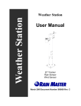
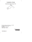
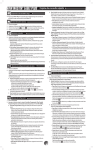
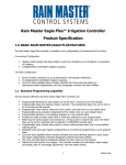
Weather Center II User Manual Part # 500009 Rev. D Weather Center II Rain Master Irrigation Systems Weather Center II User Manual Table of Contents 1.0 Introduction .....................................................................................1 1.1 Determining Weather Center II Location ......................................3 1.1.1 Weather Center Site Overview ..............................................3 1.2 General Information.......................................................................8 2.0 Weather Center Installation...........................................................9 2.1 Evolution DX2 Controller Wiring ...............................................20 2.2 RME Eagle Controller Wiring .....................................................21 3.0 Weather Center Instrumentation ................................................24 3.1 Features and Benefits ...................................................................24 3.2 Weather Center Theory of Operation...........................................26 3.3 ET Electrical Interface .................................................................26 3.3.1 Evolution DX2 Weather Interface .......................................26 3.3.2 RME Eagle Weather Interface.............................................26 4.0 Reading the ET Values .................................................................29 4.1 At the Evolution DX2 Controller.................................................29 4.2 At the RME Eagle Controller.......................................................29 4.2.1 Weather Center Status Display ................................................31 5.0 Rain Fall Sensor ............................................................................33 5.1 At the Evolution DX2 Controller.................................................33 5.1.1 Features and Benefits...........................................................33 5.1.2 Rain Fall Sensor Theory of Operation.................................33 5.1.3 Rain Fall Sensor Installation................................................34 5.1.4 Rain Fall Sensor Information...............................................34 5.1.5 Rain Fall Sensor Interface ...................................................34 5.1.6 Reading Rain Fall Sensor Values ........................................35 5.2 At the RME Eagle Controller.......................................................35 5.2.1 Features and Benefits...........................................................35 5.2.2 Rain Switch Sensor Theory of Operation ............................35 5.2.3 Rain Switch Installation.......................................................36 5.2.4 Rain Switch Sensor Information..........................................36 5.2.5 Rain Switch Sensor Interface...............................................36 6.0 Wind Speed Sensor .......................................................................37 6.1 At the Evolution DX2 Controller.................................................37 6.1.1 Features and Benefits...........................................................37 Page i Weather Center II User Manual Rain Master Irrigation Systems 6.1.2 Wind Speed Sensor Installation Checks ..............................37 6.1.3 Wind Speed Sensor Information..........................................37 6.1.4 Wind Speed Sensor Interface...............................................37 6.1.5 Reading Wind Speed Values at the Controller ....................38 6.2 At the RME Eagle Controller.......................................................38 6.2.1 Features and Benefits...........................................................38 6.2.2 Wind Speed Sensor Installation Checks ..............................38 6.2.3 Wind Speed Sensor Information..........................................38 6.2.4 Wind Speed Sensor Interface...............................................38 6.2.5 Reading Wind Values at the Controller...............................38 7.0 Maintenance...................................................................................38 7.1 Weather Center Maintenance.......................................................38 7.1.1 Wind Speed Sensor..............................................................38 7.1.2 Rain Fall Sensor...................................................................39 7.1.3 Temperature and Humidity Sensor ......................................39 7.1.4 Solar Radiation Sensor ........................................................39 7.1.5 Bird Wire .............................................................................39 7.1.6 Weather Tower Assembly ...................................................40 7.1.7 Weather Computer...............................................................40 8.0 Troubleshooting.............................................................................41 8.1 Unusually High or Low ET Readings..........................................41 8.2 Troubleshooting Flow Charts.......................................................41 8.2.1 Symptom: Low ET Reading ................................................42 8.2.2 Symptom: No ET Reading...................................................43 8.2.3 Symptom: No Rain Reading – Evolution DX2 ...................45 8.2.4 Symptom: No Rain Reading – RME Eagle .........................47 8.2.5 Symptom: No Wind Reading...............................................48 8.3 Verification of Weather Computer Input .....................................50 8.3.1 At the Evolution DX2 Controller ........................................50 8.4 Rain Fall Sensor Verification Procedure......................................52 8.4.1 At the Evolution DX2 Controller ........................................52 8.4.2 At the RME Eagle Controller ..............................................53 8.5 Verification of Rain Fall Sensor Electronics ...............................54 8.5.1 At the Evolution DX2 Controller ........................................54 8.6 Wind Speed Sensor Verification Procedure.................................55 8.6.1 At the Evolution DX2 Controller ........................................55 RAIN MASTER LIMITED WARRANTY.........................................56 Page ii Rain Master Irrigation Systems Weather Center II User Manual Table of Figures Figure 1 - Evolution Weather Center II ....................................................2 Figure 2 - Evolution Weather Center Configuration ................................3 Figure 3 - Base Mounting Bolt Installation ..............................................9 Figure 4 - Eyebolt Assembly Procedure .................................................10 Figure 5 - Eyebolt Assembly Procedure .................................................11 Figure 6 - Weather Center Base Mounting .............................................11 Figure 7 - Weather Center Tower Mounting ..........................................13 Figure 8 - Sensor Mounting Configuration.............................................14 Figure 9 - Weather Center Terminal Access...........................................16 Figure 10 - Weather Center Tower Wiring Detail ..................................17 Figure 11 - Evolution DX2 Wiring Detail ..............................................18 Figure 12 - Evolution Weather Computer Installation............................19 Figure 13 - Weather Computer ...............................................................20 Figure 14 - Weather Center Evolution DX2 Controller..........................21 Figure 15 - RME Eagle Wiring Diagram................................................22 Figure 16 - Eagle Weather Computer Wiring Diagram ..........................23 Figure 17 - Eagle-SP Stainless Enclosure Installation............................24 Figure 18 - RME Eagle Sensor Interface Connections ...........................27 Figure 19 - Bird Wire Installation...........................................................40 Table of Tables Table 1 - Sensor Placement.......................................................................5 Table 2 - Weather Center Configuration...................................................6 Table 3 - Required Equipment - Evolution DX2 Controller.....................7 Table 4 - Required Equipment - RME Eagle Controller...........................7 Table 5 - Required Site Materials .............................................................8 Table 6 - Replacement Parts List ..............................................................8 Table 7 - RME Eagle Sensor Interface Connections ..............................27 Table 8 - Sensor Specifications...............................................................28 Table 9 - Interconnect Cables .................................................................52 Page iii Rain Master Irrigation Systems 1.0 Weather Center II User Manual Introduction The Weather Center II is comprised of four major measurement sensors, these include: • • • • The Solar Radiation Sensor Temperature/Relative Humidity Sensor The Rain Fall Sensor The Wind Speed Sensor (Anemometer) The Weather Center II calculates Evapotranspiration (ET) and measures rain and wind speed. The measured sensor values are received by the Rain Master Weather Computer which resides inside the attached Evolution DX2/Eagle Controller. The Weather Computer, using the various sensor inputs, will then calculate and output, as necessary, a controlled pulse for each 0.01 inches of ET. The pulse which is output by the Weather Computer is received, stored and provided to the Evolution Central Computer system as requested (or used by the RME Eagle Controller directly and provided to the iCentral as requested). The Evolution Central Computer system uses the weather data to recalculate the irrigation schedules for all satellites associated with a particular microclimate. The new schedule is then downloaded to the field irrigation controllers. Each of the measuring devices is permanently mounted onto a vandalresistant tower with all connections made within the tower’s terminal block. Power for the Weather Computer is supplied via the Evolution DX2 controller enclosure to which the Weather Center II is connected. Figure 2 - Evolution Weather Center Configuration illustrates the complete Weather Center configuration. Page 1 Weather Center II User Manual Rain Master Irrigation Systems Figure 1 - Evolution Weather Center II Page 2 Rain Master Irrigation Systems Determining Weather Center II Location Height of Tree (T) 1.1 Weather Center II User Manual H 10H 10T Figure 2 - Evolution Weather Center Configuration 1.1.1 Weather Center Site Overview Wind, air temperature, and humidity mesurements are affected by surface type and roughness, soil moisture, regional topography and obstructions. Sites selected for their applicability to a broader area should be free from obstructions such as buildings, trees, and steep slopes. Towers are often used to raise measurement heights above lowlying obstructions. A general rule for determining the best location for the Weather Center II is to locate the Weather Center II in a turf grass area that receives full day sun and that best represents the watering needs and changes of all the Page 3 Weather Center II User Manual Rain Master Irrigation Systems irrigation zones, for that microclimate. The following general rules will help you determine the best location: Mount in an open area, clear of all obstructions. The area should be in direct sunlight, away from buildings, trees or other objects, which may restrict wind movement or cast shadows. Avoid locations that will generate reflective heat (buildings, parking lots, roadways, etc.) Excessive heat generated from these objects will cause distorted ET readings. Locate in an area that will prevent the sensor assemblies from becoming wet by the irrigating water. Areas that should be avoided are: 1. Large industrial heat sources 2. Rooftops 3. Steep slopes 4. Sheltered hollows 5. High vegetation 6. Shaded areas 7. Swamps 8. Area where snow drifts occur 9. Low places which hold standing water after rains The following table lists the suggested measured heights and exposure (distance to an obstruction) for each type of sensor. Page 4 Rain Master Irrigation Systems Weather Center II User Manual Table 1 - Sensor Placement Sensor Type Measurement Height Exposure Considerations Wind 3.0 meters +/- 0.1 meters is recommended (AASC). No closer than ten times the obstructions height. 2.0 meters +/- 0.1 meters, ten meters +/- 0.5 meters (optional) AASC. Ten meters (WMO & EPA) Air Temperature Two meters for temperature only (EPA). Two Meter and 10 meter for temperature difference (EPA). Relative Humidity The EPA recommends the sensor be no closer than four times the obstructions height. 1.5 meter +/- 1 meter The sensor must be housed (AASC). in a ventilated radiation 1.25 – 2.0 meters (WMO) shield to protect the sensor from thermal radiation. The EPA recommends the sensor be no closer than four times the obstruction’s height and least 30 meter from large paved areas. Solar Radiation Height should be consistent with the exposure standard (AASC, WMO, and EPA). To facilitate leveling/cleaning, CSI recommends installing at a height of 3 meters or less. The sky should not be blocked by any surrounding object. However, objects < 10 degree above the horizontal plane of the sensor are allowed. Precipitation 1.0 meters +/- 0.2 meter AASC & EPA suggest the Page 5 Weather Center II User Manual Rain Master Irrigation Systems (AASC) 30 cm minimum (WMO) be no closer than four times the obstruction height. The orifice of the gage must be in a horizontal plane, open to the sky, and above the level of in-splashing and snow accumulation. Table 2 - Weather Center Configuration Part Number Description Quantity EV-SEN-WD EV-WETHRCMPTR Anemometer Assembly 1 Weather Computer Assembly 1 EV-SEN-RN Rain Fall Sensor Assembly 1 EV-PS Power Supply, 12V DC Reg. 1 ET-610 Hand Tool, 610 OW Removal 1 020-0104 1 650-0010 Tower, ET/Weather, 10 foot Solar Radiation Sensor Assembly Relative Humidity/Temperature Sensor Assembly 1 500009 Manual, Weather Center 1 650-0011 Page 6 1 Rain Master Irrigation Systems Weather Center II User Manual Table 3 - Required Equipment - Evolution DX2 Controller Part Number DX-FLOW EV-CABWS12 User Supplied User Supplied User Supplied User Supplied User Supplied User Supplied Description Evolution DX2 Controller equipped with optional DXFLOW (Flow and Weather sensing) Cable, 12 conductors, 18-gauge stranded, foil shield w/drain, direct burial. (Order to length, maximum length 500 ft.) Quantity 1 1 Crescent wrench 3/8, 5/16, 7/16 inch socket wrench Screwdriver, flat blade 1 8 foot step ladder PVC Conduit 1 inch, for tower base wiring. PVC 1 inch elbow 1 1 1 4 feet 1 Table 4 - Required Equipment - RME Eagle Controller Part Number RME6EG – RME36EG Description Quantity RME Eagle Controller 1 EV-CABWS12 PC18TRANS User Supplied Cable, 12 conductors, 18-gauge stranded, foil shield w/drain, direct burial. (Order to length, maximum length 500 ft.) Transisit Suppression Circuit Board. Crescent Wrench 1 1 1 Page 7 Weather Center II User Manual User Supplied User Supplied User Supplied User Supplied User Supplied Rain Master Irrigation Systems 3/8, 5/16, 7/16 inch socket wrench Screwdriver, flat blade 8 foot step ladder PVC Conduit 1 inch, for tower base wiring. PVC 1 inch elbow 1 1 1 4 feet 1 Table 5 - Required Site Materials Part Number User Supplied User Supplied Description Concrete and masonry Sand Standard masonry tools Quantity 1 1 Table 6 - Replacement Parts List Part Number 650-0005 651-0011 EV-WETHRCMPTR 650-0011 650-0010 651-0009 1.2 Description Replacement Screen Tipping Bucket Anemometer Wind Cup Assembly Weather Center II Computer Solar Radiation Sensor Assembly Relative Humidity/Temperature Sensor Assembly Anemometer Bearing Component Type Rain Wind ET ET ET ET/Wind General Information The mounting bolts for the Rain Gauge, Wind Sensor and tower mounting bracket, are pre-installed on the tower mast. These bolts will need to be removed prior to assembly and installation. Page 8 Rain Master Irrigation Systems 2.0 Weather Center II User Manual Weather Center Installation Use the following step to assembly the Weather Center tower. Step 1 Prepare and pour a concrete support slab according to the enclosed drawing, see Figure 6 - Weather Center Base Mounting. Use the provided template to set the 5/16" mounting eye bolts. The bracket must be level and plumb. The conduit should extend at least 2 inches above the horizontal of the concrete. Figure 3 - Base Mounting Bolt Installation Page 9 Weather Center II User Manual Rain Master Irrigation Systems Figure 4 - Eyebolt Assembly Procedure Page 10 Rain Master Irrigation Systems Weather Center II User Manual Figure 5 - Eyebolt Assembly Procedure Figure 6 - Weather Center Base Mounting Page 11 Weather Center II User Manual Rain Master Irrigation Systems Step 2 Install the 12-conductor cable (EV-CAB-WS12) from the controller to the Weather Center through the conduit. From the Weather Center tower to the controller allow a minimum of 36 inches of cable to extend beyond the conduit into the controller’s pedestal cabinet. On the Weather Center tower, allow a minimum of 70 inches of cable to extend beyond the conduit into the Weather Center tower assembly. Step 3 Attach the tower to the Weather Center mounting bracket using the 3/8-inch cross-bolts (see Figure 7 - Weather Center Tower Mounting). Page 12 Rain Master Irrigation Systems Weather Center II User Manual Figure 7 - Weather Center Tower Mounting Page 13 Weather Center II User Manual Step 4 Rain Master Irrigation Systems Using a 7/16-inch socket wrench; remove the four Extension arm mounting bolts from the tower mast. Attach the Rain Fall sensor to the tower and insert the signal cable, with connector, through the 5/8-inch hole in the side of tower (See Figure 8 - Sensor Mounting Configuration). Figure 8 - Sensor Mounting Configuration Page 14 Rain Master Irrigation Systems Weather Center II User Manual Step 5 Attach the wind cup assembly to the anemometer and secure the assembly to the shaft using the provided Allen wrench. Step 6 Attach the anemometer to the tower and insert the signal cable, with connector, through the 5/8-inch hole in the side of tower. (See Figure 8 - Sensor Mounting Configuration) Step 7 Remove the lower access plate using the supplied hand tool (ET-610). Drop the cable all the way down the tower mast until it is accessible through the lower access panel. Mate the connectors to the Weather Center terminal bracket connectors (See Figure 9 - Weather Center Terminal Access and Figure 10 - Weather Center Tower Wiring Detail). Page 15 Weather Center II User Manual Rain Master Irrigation Systems Figure 9 - Weather Center Terminal Access Page 16 Rain Master Irrigation Systems Weather Center II User Manual Figure 10 - Weather Center Tower Wiring Detail Page 17 Weather Center II User Manual Rain Master Irrigation Systems Figure 11 - Evolution DX2 Wiring Detail Page 18 Rain Master Irrigation Systems Weather Center II User Manual Figure 12 - Evolution Weather Computer Installation Page 19 Weather Center II User Manual Rain Master Irrigation Systems Figure 13 - Weather Computer 2.1 Evolution DX2 Controller Wiring Step 1 Turn off power to the Evolution DX2 Controller using the AC power switch. Step 2 Connect the remaining ends of the EV-CAB-WS12 (12 conductor) cable to the sensor terminal board and/or Weather Computer at the Evolution DX2 Controller according to the color code and wiring diagram supplied (see Figure 11 - Evolution DX2 Wiring Detail). Step 3 Locate the 12 Volt DC DX2 Evolution Power Supply assembly (EV-PS). Step 4 Refer to Figure 14 - Weather Center Evolution DX2 Controller. Mount the power supply terminal strip to the top of the Sensor Terminal board located on the inside panel of the Evolution DX2 Controller enclosure using the two supplied screws. Page 20 Rain Master Irrigation Systems Weather Center II User Manual Figure 14 - Weather Center Evolution DX2 Controller 2.2 Step 5 Plug the 12 VDC power supply (EV-PS) into the Evolution DX2 Controller’s internal AC receptacle. Step 6 Connect the red and black wires of the Weather Center cable (417-0059) from the Weather Computer terminal block to the DX2 terminal strip. (See Figure 11 Evolution DX2 Wiring Detail). Step 7 Turn on power to the Evolution DX2 Controller using the AC power switch. Step 8 Secure the Weather Center Tower access cover as necessary. This completes the Weather Center installation. RME Eagle Controller Wiring Step 1 Turn off power to the RME Eagle Controller using the AC power switch. Step 2 Connect the remaining ends of the EV-CAB-WS12 (12 Page 21 Weather Center II User Manual Rain Master Irrigation Systems conductor) cable to the sensor terminal board and/or Weather Computer according to the color code and wiring diagram supplied (see Figure 15 - RME Eagle Wiring Diagram). Step 3 Locate the 12 Volt DC Power Supply assembly (EV-PS). Step 4 Plug the 12 VDC power supply (EV-PS) into the enclosures internal AC receptacle. Step 5 Connect the red and black wires to the Weather Computer terminals 1 & 2. (See Figure 15 - RME Eagle Wiring Diagram). Step 6 Turn on the power to the RME Eagle Controller use the AC power switch. Step 7 Secure the Weather Center Tower access cover as necessary. This completes the Weather Center installation. Note: The Weather Computer must be isolated from the enclosure. The installation kit includes three (3) nylon stand-offs which must be installed between the enclosure back plate and the Weather Computer mounting plate surface. Figure 15 - RME Eagle Wiring Diagram Note: The Weather Computer must be isolated from the enclosure. The installation kit includes three (3) nylon standoffs which must be installed between the enclosure back plate and the Weather Computer mounting plate surface. Page 22 Rain Master Irrigation Systems Weather Center II User Manual Figure 16 - Eagle Weather Computer Wiring Diagram Page 23 Weather Center II User Manual Rain Master Irrigation Systems Figure 17 - Eagle-SP Stainless Enclosure Installation 3.0 Weather Center Instrumentation 3.1 Features and Benefits The Rain Master Weather Computer is a precision electronic instrument that calculates Evapotranspiration (ET). The Weather Computer, using Solar Radiation, Temperature, Relative Humidity, and Wind Speed will calculate ET to an accuracy of 0.01 inches. The calculations are based on the approved American Society of Civil Engineers (ASCE) Formula, which simulates water transpiration and soil moisture evaporation (water lost) of irrigated cool season turfgrass, in direct sunlight. Page 24 Rain Master Irrigation Systems Weather Center II User Manual The Rain Master Weather Center allows the irrigation system to optimize water usage by replacing only as much water as was used by the turfgrass. The simplicity of the system has given it a major advantage in cost and effectiveness. The Rain Master Weather Center II will directly model the ET (evapotranspiration) on any given site. The factors below are accounted for by the system: • • • • Air Temperature Wind Speed Relative Humidity Solar Radiation All of the above factors must be constantly monitored and measured, with average readings produced, and finally logged. The Weather Computer automatically and directly reads every change throughout the measurement period, and factors it directly into the ET calculations. Summary: • • • • • Precise readings of ET values Direct modeling of a microclimate Very low to no maintenance for a full season Inexpensive to purchase and operate Does not require shutdown or preventive measures during freeze With the use of the Rain Master Evolution Central Computer or the RME Eagle iCentral, daily accumulated ET readings are processed and watering schedules are adjusted accordingly. When a watering zone microclimate is hot, windy or dry, the ET values will increase resulting in a heavier watering schedule. When the microclimate becomes cooler or increases in humidity, the watering schedule will be adjusted to a lower percentage of station run times, thus reducing water usage. The Rain Master Weather Center is connected to one controller of an irrigation system, which is set up to gather accumulated ET data for the 24 hour period between 12:00 AM and 12:00 midnight. The final totals are uploaded to the Evolution Central Computer each day for processing and reports. Page 25 Weather Center II User Manual 3.2 Rain Master Irrigation Systems Weather Center Theory of Operation The principle of the Rain Master Weather Center II is to directly measure the effects of weather and estimate the evapotranspiration loss of water from the reference crop (i.e. Turfgrass). Transpiration is the movement of water from plant tissues directly into the atmosphere. Evapotranspiration is the sum of transpiration and water evaporated from the soil where water may have accumulated from irrigation, and/or rainfall. The Rain Master Weather Center calculates the effects of solar radiation, wind, humidity and temperature on cool season turfgrass every 10 seconds and as required, outputs one or more Evapotranspiration pulses, where it is recorded at the rate of one pulse for every 0.01 inches of water loss. The accumulated pulses are output, by the Weather computer every 10 minutes, as required. 3.3 ET Electrical Interface 3.3.1 Evolution DX2 Weather Interface The ET pulse is provided to the Evolution DX2 controller through a sensor circuit board (DX-FLOW). The pulse is shaped at the sensor board and forwarded to the controller board for accumulation. 3.3.2 RME Eagle Weather Interface The ET pulse is provided directly to the RME Eagle Controller at the sensor input connector as depicted in Figure 18 - RME Eagle Sensor Interface Connections. Page 26 Rain Master Irrigation Systems Weather Center II User Manual J12 J4 J5 1 2 3 4 5 6 INPUT (SILVER) RAIN SENSOR 24VAC (COPPER) ET – (WHITE WITH BLUE STRIPES) ET + (BLUE) ET DEVICE – (BLK) + (WHT) FLOW Figure 18 - RME Eagle Sensor Interface Connections Table 7 - RME Eagle Sensor Interface Connections Sensor Name Rain Input Rain 24 VAC Flow + Flow ET + ET - Connector Number (J12) 1 2 3 4 5 6 Color Code Silver Copper White Black Blue White w/Blue Stripe Page 27 Weather Center II User Manual Rain Master Irrigation Systems Sensor Accuracy: +/-1% of evapotranspiration. Sensor Resolution: Sensor Output: Sensor Capability: 0.01 inch reference Evapotranspiration ( ET). A single pulse per 0.01 inch of ET. Solar Radiation, Air Temperature, Relative Humidity, Wind Speed. Connects directly into a Rain Master Evolution DX2 controller equipped with a sensor board. The ET is read directly from the Evolution DX2 controller by the Evolution Central Computer. Installation: Dimensions: Shipping Weight: Mounting: Materials: Electrical Signal: Impedance: Transient Protection: Power Source Freeze Protection: Connects directly to the RME Eagle Controller. The ET is read and used directly by the RME Eagle Controller. The Rain Master iCentral Internet site can request this data from the RME Eagle Controller. 120.0 inches high x 4.0 inches in diameter, the tower base is 12.0 inches x 12.0 inches 81 pounds Inside Weather Center tower G5055 White Poly-vinyl Chloride (PVC) housing Electrical signal is pulsed low for 2.0 (+/- .07) seconds after each 0.01” ET pulse. Normally open circuit of 53 OHMS during pulse. (Max voltage from receiving equipment: 12V DC) Full lightning protected, except direct strikes to the unit. 12 Volts DC, provided by plug-in transformer. Unit will continue to work below freezing temperatures. Table 8 - Sensor Specifications Page 28 Rain Master Irrigation Systems 4.0 Reading the ET Values 4.1 At the Evolution DX2 Controller Weather Center II User Manual The ET values may be read from the display of the Evolution DX2 controller by following the steps listed below. Advance to the ET Sensor screen through the following menu sequences: F1 = Main Menu F3 = Status F2 = Measurements F4 = ET SUN MON TUE WED THU FRI SAT .07 .08 .11 .10 .14 .09 .11 ET-INCHES | ↑ | The ET Sensor screen displays seven consecutive days of ET readings, from Sunday through Saturday. Each day displays the ET reading in 1/100th of an inch (0.01”). One day represents a 24-hour period beginning at midnight. Using the Evolution Central Control system, the accumulated ET values can be stored by the day and by the week for any period of time desired. At midnight, the current ET value will be replaced with a zero (0) and a new days ET value will start to accumulate. Note: 4.2 Although the ET readings are continuously updated, the latest readings will not appear on screen. To read the most recent values, exit the ET screen using the up arrow then return to the ET screen by pressing F4. At the RME Eagle Controller The RME EAGLE controller is capable of reading, processing and storing the accumulated values received from a Rain Master Weather Center. The Weather Center provides a single count for Page 29 Weather Center II User Manual Rain Master Irrigation Systems each .01 inch change in ET. The RME EAGLE controller will accumulate the Weather Center counts from midnight to midnight (24 hour accumulation) and store the total for use in the next day station runtime calculations. The total number of counts received from the Weather Center will increase or decrease based on weather conditions and will change through-out the year (i.e. summer to winter, hot to cold). This change in counts will then affect the length of watering on a day to day basis. EXAMPLE: Turn on the Weather Center Device. Continue to Press: ET Until display indicates: DVICE OFF PROGRAM Press: MON 1 ENTER The 1 key acts as a toggle key when used in this ET configuration item. Display will indicate: DVICE ON PROGRAM Press: Page 30 QUIT Rain Master Irrigation Systems Weather Center II User Manual The controller will return to the Automatic Mode. EXAMPLE: Review Status of the Weather Center Device. Continue to Press: ET Until display indicates: DVICE ON PROGRAM OR DVICEOFF PROGRAM Press: QUIT The controller will return to Automatic Mode. 4.2.1 Weather Center Status Display Once the Weather Center device has been enabled (DVICE ON), the next ET parameter display will be the current day’s accumulated values received from a Weather Center interface. The Weather Center status display will provide the total number of counts received since last midnight. Current day accumulation will complete at midnight and will then be used in tomorrow’s calculation of station watering time. NOTE: The accumulated Weather Center count will only be valid and used, after a Page 31 Weather Center II User Manual Rain Master Irrigation Systems complete 24 hour accumulation period (midnight to midnight). The value will then be used for all next day and future day calculations. NOTE: If controller power is lost for more then one hour, the Weather Center count will be invalidated and the controller will store and use Historical ET data for the current day accumulation. The display indicates the total ET (measured in inches) accumulated since midnight. EXAMPLE: Review today’s Weather Center accumulated ET. Continue to Press: ET Until display indicates: DCNT .18 PROGRAM NOTE: Press: The Weather Center Device Status display will not be presented if the Weather Center Device has not been enabled. QUIT The controller will return to the Automatic Mode. Page 32 Rain Master Irrigation Systems 5.0 Rain Fall Sensor 5.1 At the Evolution DX2 Controller Weather Center II User Manual Note: Rain Fall sensor management can only be performed through the use of the Evolution Central Computer. 5.1.1 Features and Benefits The RMIS Rain Fall sensor provides accurate rainfall measurements (to the nearest 0.01 inch) and storage of rainfall data. Because the sensor interfaces directly to any Evolution DX2 Controller, the user can select the most appropriate rainfall data collection location. The Rain Fall sensor provides the following system benefits: • • • Automatic rain condition system shutdown Calculation of root zone moisture depletion Rainfall data reports 5.1.2 Rain Fall Sensor Theory of Operation The Rain Fall sensor is an internal component comprised of two reservoirs configured on a balanced seesaw type mechanism. As rainfall enters the outer collecting funnel-shaped container, one of the two reservoirs will fill up to a capacity of 0.01 inch of water. When the water level reaches the 0.01 inch capacity, the weight of the water causes the mechanism to flip to one side and the water is emptied out, placing the remaining reservoir in position to collect new water. When the second reservoir reaches the 0.01 inch capacity, the mechanism flips back to the original position, exposing the first reservoir. All discarded water drains out the bottom of the outer housing. This process continues throughout the rainfall period. Whenever the tipping bucket mechanism flips to one side or the other, an electrical pulse is generated by means of an inverted pendulum action and fed directly to the sensor terminal board (Input 3). The incoming pulse is collected to produce a reading of 0.01 inch (1/ 100th of an inch) at the controller display screen. Page 33 Weather Center II User Manual 5.1.3 Rain Master Irrigation Systems Rain Fall Sensor Installation The housing of the Rain Fall Sensor should be level. After installation is complete, check to make sure that the Rain Fall sensor is not held in a dead center position by pressing either end down against the stop. 5.1.4 Rain Fall Sensor Information Accuracy: 1.0% at 2 inches per hour or less. Maintenance: Occasional cleaning of debris from the filter screen may be required. 5.1.5 Rain Fall Sensor Interface The two wires from the Rain Fall sensor are connected to Input 3 ( + ) and Input 3 ( - ) of the Sensor Terminal board. It does not matter which wire goes to which terminal. This is depicted in Figure 11 Evolution DX2 Wiring Detail. Page 34 Rain Master Irrigation Systems 5.1.6 Weather Center II User Manual Reading Rain Fall Sensor Values To insure that all cables are properly connected, the Rain Fall Sensor reading should be checked at the Evolution DX2 Controller. Proceed to the Rain/Wind display through the following menu sequences: F1 = Main Menu F3 = Status F2 = Measurements F4 = Rain/Wind RAIN = 000.01/INCH WIND = 012 MPH 5.2 At the RME Eagle Controller 5.2.1 Features and Benefits |↑| The RMIS Rain Switch sensor is used with the RME Eagle Controller to provide rainfall measurements (to the nearest 0.125 inches). Because the sensor interfaces directly to the RME Eagle Controller, the user can select the most appropriate rainfall data collection location. The Rain Switch sensor provides the following system benefits: • • 5.2.2 Automatic rain condition system shutdown Rain Switch sensor status Rain Switch Sensor Theory of Operation The Rain Switch sensor is manually set to the desire level of rainfall which must occur prior to the automatic shut-down of the RME Eagle Controller. The Rain Switch sensor can be set to trigger at 0.125, 0.250, 0.500, and 0.750 inches of rainfall. The sensor contains a moisture absorbent material that will expand when wet, as water continues to be absorbed, the material will expand and at the selected setting a switch closure will occur. Upon switch closure the RME Eagle controller will indicate a WET Page 35 Weather Center II User Manual Rain Master Irrigation Systems condition and evaluate which irrigation programs are associated to the Rainfall sensor, programs so designated will be inhibited from activating the associated valves. After the rainfall has ended the rainfall sensor will start to dry out, the material will start to contract and eventually the switch will again open. The RME controller will then indicate a DRY condition and the RME Eagle controller will again start to irrigate. 5.2.3 Rain Switch Installation The housing of the Rain Switch sensor should be level. After installation is complete, check to make sure that the Weather Center is level and plumb. 5.2.4 Rain Switch Sensor Information Accuracy: 0.125 inches of rainfall Maintenance: Occasional cleaning of the housing is necessary. 5.2.5 Rain Switch Sensor Interface The two wires from the Rain Switch sensor are connected to Pin 1 ( Input ) and Pin 2 ( 24 VAC ) of the Sensor Terminal connector, marked J12. This is depicted in Figure 15 - RME Eagle Wiring Diagram. Note: Rain Switch sensor management can be performed through the use of the RME Eagle Setup parameters. J12 J4 J5 1 2 3 4 5 6 INPUT (SILVER) RAIN SENSOR 24VAC (COPPER) ET – (WHITE WITH BLUE STRIPES) ET + (BLUE) – (BLK) + (WHT) Page 36 FLOW ET DEVICE Rain Master Irrigation Systems 6.0 Wind Speed Sensor 6.1 At the Evolution DX2 Controller Note: 6.1.1 Weather Center II User Manual Wind Speed sensor data management can only be performed through the use of the Evolution Central Computer system. Features and Benefits When used with a Rain Master Evolution Central Computer System, wind speed sensing provides the following features and benefits: • • • 6.1.2 Automatic system shutdown for wind (Wind too high) Automatic wind start up (Wind calm enough for normal operation) Graph of the last three hours of wind data at Evolution Central Computer Wind Speed Sensor Installation Checks Check to see that the cup assembly of the Wind Speed sensor rotates freely and does not drag to a stop. 6.1.3 Wind Speed Sensor Information Accuracy: +/- 1.5% or 0.25 mph Maintenance: The Wind Speed sensor bearings should be replaced every 12 to 24 months. The Wind Speed sensor should be rebuilt every 24 to 36 months. 6.1.4 Wind Speed Sensor Interface The two wires from the Wind Speed sensor are connected to Input 4 ( + ) and Input 4 ( - ) on the Sensor Terminal board via the Weather Center terminal block. Either wire may be connected to either terminal connection. Page 37 Weather Center II User Manual 6.1.5 Rain Master Irrigation Systems Reading Wind Speed Values at the Controller Refer to paragraph 5.1.6 Reading Rain Fall Sensor Values at the Evolution DX2 Controller. 6.2 At the RME Eagle Controller 6.2.1 Features and Benefits When used with a RME Eagle Controller the Wind Speed Sensor values are provided directly to the Rain Master Weather Computer for use in Evapotranspiration (ET) calculations only. 6.2.2 Wind Speed Sensor Installation Checks Check to see that the cup assembly of the Wind Speed sensor rotates freely and does not drag to a stop. 6.2.3 Wind Speed Sensor Information Accuracy: +/- 1.5% or 0.25 mph Maintenance: The Wind Speed sensor bearings should be replaced every 12 to 24 months. The Wind Speed sensor should be rebuilt every 24 to 36 months. 6.2.4 Wind Speed Sensor Interface The two wires from the Wind Speed sensor are connected to Terminal Pin 2 and Terminal Pin 5 on the Weather Computer. 6.2.5 Reading Wind Values at the Controller The wind sensor speed can not be directly read or displayed on the RME Eagle controller. 7.0 Maintenance 7.1 Weather Center Maintenance 7.1.1 Wind Speed Sensor The bearings of the anemometer should be inspected once a year or once per irrigation season, by turning the wind cups. No friction or wobble should be present. If the bearings require replacement, return the Page 38 Rain Master Irrigation Systems Weather Center II User Manual complete anemometer assembly to the factory. 7.1.2 Rain Fall Sensor The Rain Fall or Rain Switch sensor should be visually inspected at least once a year or once per irrigation season to ensure no leaves, bird droppings or debris have accumulated within. To clean the Rain Fall Sensor, remove the top funnel unit and tip the screen out onto your hand. Wash the screen thoroughly and reassemble the top funnel unit. To clean the Rain Switch Sensor, throughtly wash any accumulated debris from the top surface of the unit. Validate proper operation of the unit by clicking the switch on and off by freely pressing the top of the spindle. 7.1.3 Temperature and Humidity Sensor The Temperature and Humidity Sensor should be visually inspected at least once a year or once per irrigation season to ensure no leaves, bird droppings or debris have accumulated within or on the stainless steel screen. To clean the screen use a small hard bristle brush to loosen any accumulated debris. Rinse with clean water which is not under pressure, such as a spray bottle. 7.1.4 Solar Radiation Sensor The Solar Radiation sensor should be visually inspected at least once a year or once per irrigation season to ensure no bird droppings or debris have accumulated on the sensor. To clean the sensor use a soft damp cotton cloths to remove any accumulated debris. 7.1.5 Bird Wire One stainless steel "bird wire" is included with the Weather Center II Assembly. The 6 inch wire is held vertically by inserting the bottom end in the small hole located on the surface of the white PVC end cap, located next to the solar radiation sensor. (See Figure 19 - Bird Wire Installation). The wire will keep birds from perching on the instrument. Page 39 Weather Center II User Manual Rain Master Irrigation Systems Figure 19 - Bird Wire Installation 7.1.6 Weather Tower Assembly The Weather Tower Assembly should be visually inspected at least once a year or once per irrigation season to ensure mechanical stability of the tower and the attached sensors. 7.1.7 Weather Computer The Weather Computer should be visually inspected at least once a year or once per irrigation season to ensure that the system is free of any debris. Verify that all cables/connectors are properly seated in the terminal block. Page 40 Rain Master Irrigation Systems 8.0 Weather Center II User Manual Troubleshooting If any of the conditions listed below should develop in the Weather Center readings, a problem may exist within one or more of the sensors. Use one or more of the following troubleshooting steps to correct the error readings: • • • • • 8.1 Unusually high ET readings Unusually low ET readings No ET readings No Rain Sensor readings No Wind Sensor readings Unusually High or Low ET Readings The Weather Center II will not provide proper measurements if one or more of the sensor assemblies are not functional. 8.2 Troubleshooting Flow Charts The following troubleshooting flow charts address typical field problems and probable causes. Page 41 Weather Center II User Manual Rain Master Irrigation Systems 8.2.1 Symptom: Low ET Reading Start 1 Is weather station located in the proper environment? No See Determining Weather Center Location. Yes 2 Are the sensors free of debris? No Refer to Chapter 7, Weather sensor Maintenance Yes 3 Does the Wind Sensor turn freely? Yes Contact Factory Page 42 No Refer to Chapter 7, Weather Center Maintenance Rain Master Irrigation Systems Weather Center II User Manual 8.2.2 Symptom: No ET Reading Start 1 Is the Weather Computer Transformer Plugged In? No Check and if necessary reset the GFI breaker. Plug in the Weather Computer Transformer Yes 2 Are the K and Offset values for Flow Sensor 2 set to Zero? No Refer to the DX2 User’s Manual (4-51), set Flow meter 2 “K and Offset” values to Zero. Yes 3 Are the sensors correctly wired to the Evolution DX2/RME Eagle Controller? No Refer to the Installation instructions. Check wiring and verify polarity. 1 Page 43 Weather Center II User Manual Rain Master Irrigation Systems 1 4 Can +5 VDC be measured at terminal inputs 2(+) and 2(-) of the Sensor Terminal Board? Disconnect the two wires from the Sensor Terminal at terminals Input 2(+) and Input 2(-) and re-measure voltage. If voltage reads 0, contact the factory. If voltage reads +5VDC, the problem is in the wiring 5 If voltage reads greater than +5 VDC, reconnect the two wires to the Sensor Terminal board Inputs 2(+) and 2(-). If voltage reads 0, check for open/shorts in cable and terminal block connections. End Note: Page 44 If the Flow Max feature (Evoution DX2 only) is utilized on the controller that the Weather Center is connected to, then the user must say Flow Meter is connected to this controller. During the Flow Max Set-Up (Refer to DX2 User Guide pages F-22 & F-23) the “K” and offset values of “0” must be entered at the sub master (Refer to DX2 User Guide). Rain Master Irrigation Systems 8.2.3 Weather Center II User Manual Symptom: No Rain Reading – Evolution DX2 Start 1 Is there any accumulation of debris on the top inside screen of the bucket? No Remove and clean screen as described in maintenance section. No Refer to Installation instructions. Check wiring and verify polarity. Yes 2 Is the rain Sensor correctly wired to the Evolution DX2 controller? Yes 3 Is there +8 Volts DC at terminal Input 3(+) and 3(-) of the Terminal board? No Disconnect the two wires from the Sensor Terminal at terminals Input 3 (+) and Input 3 (-) and re-measure voltage. If voltage reads 0, contact factory. If voltage reads +8 VDC, problem lies in wiring or rain gauge. Yes 1 Page 45 Weather Center II User Manual 1 End 4 Page 46 Rain Master Irrigation Systems If voltage reads +8 VDC, reconnect the two wires to the Sensor Terminal board Inputs 3+ and 3-. At the tower terminal block, unplug the rain gauge connector. Re-measure voltage at terminals Input 3+ and 3-. If voltage reads +8 VDC, problem lies in rain gauge. If voltage reads 0, check for shorts in cable and terminal block connections. Rain Master Irrigation Systems 8.2.4 Weather Center II User Manual Symptom: No Rain Reading – RME Eagle 1 4 If RME Eagle Is there +24 VAC at pin 2 of the sensor terminal connector? No Check cable continuity from terminal block to Sensor Terminal connector. No Check and repair cable continuity from terminal block to Rain Fall switch. Yes 5 Can +24 Volts AC be measured at the Weather tower terminal connector? 6 Contact Factory for Authorized Repair End Page 47 Weather Center II User Manual 8.2.5 Rain Master Irrigation Systems Symptom: No Wind Reading Start 1 Does the cup assembly spin freely? No Check bearings and cup assembly mounting. Yes 2 Is the Wind Sensor wired correctly to the DX2 and the Weather Computer? No Refer to the Installation instructions Check and verify wiring. Yes 3 Can +12 Volts DC be measured at terminal Inputs 4+ and 4- of the Sensor Terminal board? 1 Page 48 No Disconnect the two wires from the Sensor Terminal at terminals Input 4 (+) and Input 4 (-) and re-measure voltage. If voltage reads 0, contact factory. If voltage reads +12 VDC, problem lies in wiring or Wind Sensor. Rain Master Irrigation Systems Weather Center II User Manual Reconnect the two wires to the Sensor Terminal board. At the Weather pole terminal block, unplug the Wind Sensor from the connector. Re-measure the voltage at terminals Input 4(+) and 4(-). If voltage reads +12 VDC, the problem is the Wind Sensor. If voltage reads 0, check for shorts/opens in the cable and terminal block connections. 1 4 Can +12 Volts DC be measured at the wind terminals of the Weather Station terminal block? No Check cable continuity from terminal block to Sensor Terminal board. No Check and repair cable continuity from terminal block to rain gauge. Yes 5 Can +12 Volts DC be measured at the terminal block wind sensor plug? 6 Contact Factory for Authorized Repair End Page 49 Weather Center II User Manual Rain Master Irrigation Systems 8.3 Verification of Weather Computer Input 8.3.1 At the Evolution DX2 Controller This procedure describes the steps necessary to verify the operation of the Evolution DX2 Controller ET input. This process simulates the incoming pulses from a Rain Master Weather Computer, displaying the results on the Evolution DX2 controller ET display screen. Step 1 Disconnect the two wires from the Sensor Terminal board at terminals Input 2 ( + ) and Input 2 ( - ). Connect a short wire (14 - 12 AWG) in each of the Input 2 terminals. Step 2 Observe the controller ET display screen and note the present ET value for today. (Refer to the section on Reading ET Values at the Evolution DX2 Controller) Step 3 Press the QUIT key to return to the main display screen. (This is necessary to allow the controller to update the ET value information.) Step 4 At the Sensor Terminal board, touch the two wires together momentarily 2 or 3 times. (An ET reading of 0.01 inches should be recorded each time the wires make contact.) Step 5 Re-check the ET values on the Evolution DX2 Controller ET display screen. Verify that the readings have increased by 0.01 inches (1/100 inch) for each time the wires made contact. Step 6 This ends of ET Data Checkout procedure. If the ET value does not increase each time the wires are shorted, check the inter-connection cables, the required cables are noted in Table 9 - Interconnect Cables. 8.3.2 At the RME Eagle Controller This procedure describes the steps necessary to verify the operation of the RME Eagle Controller ET input. This process simulates the incoming pulses from a Rain Master Weather Computer, displaying the results on the RME Eagle Controller display screen. Step 1 Page 50 Press the SETUP key continuously until DCNT is Rain Master Irrigation Systems Weather Center II User Manual displayed on the RME Eagle Controller display. Step 2 Disconnect the the cable harness from J12 on the RME Eagle Controller. Using a short wire (14 - 12 AWG) touch end to pin 5 of J12 and the other side to pin 6 of J12. Step 3 Observe the controller ET display screen and note the present ET value for today. (Refer to the RME Eagle User Manual on Reading ET Values at the Controller) Step 4 Touch the two ends of the wires to the terminal pins 5 and 6 momentarily 2 or 3 times. (An ET reading of 0.01 inches should be recorded each time the wires make contact with the terminal pins) Step 5 Re-check the ET values on the RME Eagle Controller ET display screen. Verify that the readings have increased by 0.01 inches (1/100 inch) for each time the wires made contact. Step 6 This ends of ET Data Checkout procedure. If the ET value does not increase each time the wires are shorted, verifiy that the correct terminals pins are being touched. If no readings are registered contact Rain Master technical support for assistance. Page 51 Weather Center II User Manual Rain Master Irrigation Systems Table 9 - Interconnect Cables From To Sensor Terminal Board Sensor board Sensor board Main board Description 12”, 25 conductor flat ribbon cable 2”, 26 conductor flat ribbon cable Check that the cables are properly installed. If the cables check out OK, the Sensor Terminal board may be defective. Contact the factory for a replacement. 8.4 Rain Fall Sensor Verification Procedure 8.4.1 At the Evolution DX2 Controller To insure that all cables are properly connected and that the Rain Fall sensor is operational, the Rain Fall Sensor reading can be checked at the Evolution DX2 Controller. Proceed to the Rain/Wind display using the following menu sequences: F1 = Main Menu F3 = Status F2 = Measurements F5 = Rain/Wind RAIN = 000.01/INCH WIND = 000 MPH |↑| Step 1 Observe the measurement. Step 2 Remove the outer funnel-shaped rain collector from the rain gauge (top half of bucket). Step 3 Manually operate the internal dual reservoir mechanism from one side to the other several times. Each time the mechanism flips, a 0.01 inch count increase should be displayed at the Evolution DX2 controller display. Page 52 Rain Sensor display and note the Rain Master Irrigation Systems Weather Center II User Manual Step 4 Observe the Rain reading again and verify that the reading has increased by the number of times the tipping bucket mechanism was activated. Step 5 If readings change properly, the Rain Gauge and associated wiring is functioning properly. Re-assemble the funnel collector onto the rain gauge. If the Rain readings do not change, the problem must be isolated to either the Rain Gauge or the Controller. Refer to the Rain Gauge Data Checkout procedure. 8.4.2 At the RME Eagle Controller To insure that all cables are properly connected and that the Rain Switch sensor is operational, the Rain Switch Sensor reading can be checked at the RME Eagle Controller. Step 1 Continue to press the SETUP key until SNSR (sensor) is displayed. Step 2 Assign one or more irrigation program to the SNSR setup, by pressing the 1 – 4 keys and then the ENTER key to accept the input. Step 3 Press the QUIT to return to AUTOMATIC mode. Step 4 Press the PROGRAM key and then the ONE key, to select irrigation Program One. Step 5 Press the REVIEW key to review the status of the sensor. The display will indicate SNSR-DRY. Step 6 Disconnect the Rain Switch at the Sensor Terminal board (pins #1 and Pins #2). Step 7 The RME Eagle will display SNSR-WET, indicating a Rain Condition. Step 8 Re-connect the sensor wiring to pins #1 and #2. Step 9 Press the QUIT key to return to the AUTOMATIC mode. Note: If the Rain Status Display does not change, the Page 53 Weather Center II User Manual Rain Master Irrigation Systems problem must be isolated to either the Rain Switch or the Controller. 8.5 Verification of Rain Fall Sensor Electronics 8.5.1 At the Evolution DX2 Controller This procedure provides the recommended steps to check and verify the operation of the Evolution DX2 Controller Rain fall sensor input. This process simulates the incoming pulses (+ 8 volts) from a Rain Gauge, displaying the results on the controller’s Rain/Wind display screen. The following steps will assist in the isolation of the Rainfall sensor reading problems to the Rainfall sensor, the associated wiring, the Controller, or the associated Sensor terminal inputs. Step 1 Disconnect the two wires from the Sensor Terminal board at terminals Input 3 ( + ) and Input 3 ( - ). Connect a short wire (14 - 12 AWG) in each of the Input 3 terminals. Step 2 Observe the controller’s Rain display screen and note the present value displayed. Step 3 At the Sensor Terminal board, touch the two wires together momentarily 2 or 3 times. (A Rain reading of 0.01 inches should be recorded each time the wires are shorted together.) Step 4 Re-check the Rain values on the controller Rain display screen. Verify that the reading has increased 0.01 inches (1/100 inch) each time the wires were shorted. Note: If readings change properly, the Sensor Terminal Input 3 is OK and the Controller is operating properly. Rainfall sensor reading problems must therefore be associated with the Rainfall sensor or its associated wiring. Check the Rainfall sensor installation and all connections. If readings do not change properly, the problem lies within the Controller. Check the controller cables to make sure that everything is plugged in correctly. Page 54 Rain Master Irrigation Systems Weather Center II User Manual 8.6 Wind Speed Sensor Verification Procedure 8.6.1 At the Evolution DX2 Controller This procedure assumes that the wind sensor inputs 4 (+) and 4 (-) on the Sensor Terminal board are functioning properly. Proceed to the Rain/Wind display through the following menu sequences: F1 = Main Menu F3 = Status F2 = Measurements F5 = Rain/Wind RAIN = 000.01/INCH WIND = 000 MPH |↑| Step 1 If windy conditions exist, allow the anemometer to spin in the wind and observe the wind speed reading on the display. It may take up to a minute before the display begins to register a reading. Step 2 If no wind conditions exist, the anemometer cup assembly must be operated manually. This may require two people, one to operate the cup assembly for at least one minute and a second person to observe the wind speed reading. If a reading is still not displayed, the problem is in the anemometer or its associated wiring. Check all wiring and connections from the anemometer to the controller. An updated displayed reading anemometer is operating properly. Step 3 indicates that the If wind speed reading problems still exist, please contact the factory. Page 55 Weather Center II User Manual Rain Master Irrigation Systems RAIN MASTER LIMITED WARRANTY Rain Master Irrigation Systems Inc. warrants to the first customer purchaser that this Rain Master brand product (the "product"), when shipped in its original container, will be free from defective workmanship, and materials and agrees that it will, at its option, either repair the defect or replace the defective product or part thereof at no charge to the purchaser for parts or labor for the time period set forth below. This warrant does not apply to any appearance items of the product nor to any product the exterior of which has been damaged, or defaced, which has been subjected to misuse, abnormal service or handling, or which has been altered or modified in design or construction. (See additional exclusion below). In order to enforce the rights under this limited warranty, the purchaser should ship or carry the product to a Rain Master authorized service depot, or send product prepaid to Rain Master at the address below (ensuring product is packaged correctly for shipment). For nearest location, call Rain Master Service Center 1-805-527-4498. This limited warrant described above is in addition to whatever implied warranties may be granted to purchasers by law. (All implied warranties including the warranty of merchantability, and fit for use are limited to the period(s) from date of purchase set forth below). Neither the sales personnel of the seller nor any other person is authorized to make any warranties other than those described above, or to extend the duration of any warranties beyond the time period described herein. The warranties described above shall be the sole and exclusive warranties granted by Rain Master Irrigation Systems Inc. and shall be the sole and exclusive remedy available to the purchaser. Correction of defects, in the manner and period of time described herein, shall constitute complete fulfillment of all liabilities and responsibilities of Rain Master to the purchaser with respect to the product, and shall constitute full satisfaction of all claims, whether based on contract, negligence, and strict liability or otherwise. In no event shall Rain Master be liable or in any way responsible, for any damages or defects in the product which were caused by repairs or attempted repairs performed by anyone other than a Rain Master Service dealer or center. Nor shall Rain Master be liable or in any way responsible for an incidental or consequential economic or property damage. Some states do not allow the exclusion of incidental or consequential damages, so the above exclusion may not apply to you. This limited warranty does not apply to improper installation or grounding, acts of God, such as lightning and/or power surges, floods, earthquakes, hurricane, tornados, vandalism etc. Page 56 Rain Master Irrigation Systems Weather Center II User Manual The RME EAGLE Controller has a 5 year limited warrant from date of purchase. All other Rain Master Brand products carry a 2 year limited warranty unless otherwise specified. SERVICE Should it be necessary to require servicing of your controller, contact your local Rain Master distributor or contact Rain Master at 1-805-527-4498 for a listing of distributors in your area. When sending a controller or a component of the controller back to be serviced, ensure it is properly protected with a soft packaging material, and that the box will withstand normal shipping abuses. Enclose a complete description of the type of problem that is occurring, and be sure to put your name, address and phone number where you can be reached. WARNING: This equipment has been tested and found to comply with the limits for Class A digital device pursuant to Part 15 of the FCC Rules. These limits are designed to provide reasonable protection against harmful interference when the equipment is operated in a commercial environment. This equipment generates, uses, and can radiate radio frequency energy and, if not installed and used in accordance with the instructions manual, may cause interference to radio communications. Operation of this equipment in a residential area is likely to cause interference in which case the user will be required to correct the interference at his own expense. The user is cautioned that changes and modifications made to the equipment without approval of the manufacturer could void the user’s authority to operate this equipment. Rain Master Irrigation Systems 3910-B Royal Ave. Tel (805) 527-4498 www.rainmaster.com Simi Valley, CA 93063 Fax (805) 527-2813 Page 57 3910-B Royal Avenue Simi Valley, California 93063 Telephone: (805) 527-4498 Fax: (805) 527-2813 www.rainmaster.com