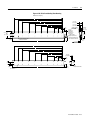
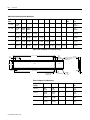
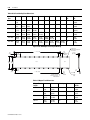
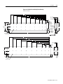
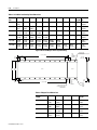
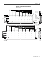
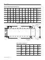
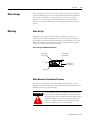
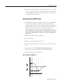
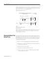
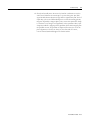
1
ANORAD
LC Series Linear Motors
USER MANUAL
October 2006
Item Number 814036
Publication Number LC-UM001C-EN-P
i
Important User Information
Because of the variety of uses for the products described in this publication,
those responsible for the application and use of this motor assembly must
satisfy themselves that all necessary steps have been taken to assure that each
application and use meets all performance and safety requirements, including
any applicable laws, regulations, codes and standards.
The illustrations, charts, sample programs and layout examples shown in this
guide are intended solely for purposes of example. Since there are many
variables and requirements associated with any particular installation, Anorad
does not assume responsibility or liability (to include intellectual property
liability) for actual use based upon the examples shown in this publication.
Reproduction of the contents of this copyrighted publication, in whole or part,
without written permission of Anorad Corporation, is prohibited.
Throughout this manual we use notes to make you aware of safety
considerations:
ATTENTION
!
Identifies information about practices or circumstances
that can lead to personal injury or death, property damage
or economic loss
Attention statements help you to:
• identify a hazard
• avoid a hazard
• recognize the consequences
IMPORTANT
Item Number 814036 - Rev C
Identifies information that is critical for successful
application and understanding of the product.
Table of Contents
Important User Information. . . . . . . . . . . . . . . . . . . . . . . . . . . . . . . . . . . . . . . . . . . . . . . . . . . . . . . . . . . . . . . . . i
Introduction
Using This Manual. . . . . . . . . . . . . . . . . . . . . . . . . . . . . . . . . . . . . . . . . . . . . . . . . . . . . . . . . . . . . . . . . . . . . .
Product Description . . . . . . . . . . . . . . . . . . . . . . . . . . . . . . . . . . . . . . . . . . . . . . . . . . . . . . . . . . . . . . . . . . . .
General . . . . . . . . . . . . . . . . . . . . . . . . . . . . . . . . . . . . . . . . . . . . . . . . . . . . . . . . . . . . . . . . . . . . . . . . . . .
Product Line Description . . . . . . . . . . . . . . . . . . . . . . . . . . . . . . . . . . . . . . . . . . . . . . . . . . . . . . . . . . . . .
Motor Features . . . . . . . . . . . . . . . . . . . . . . . . . . . . . . . . . . . . . . . . . . . . . . . . . . . . . . . . . . . . . . . . . . . . .
Maintenance . . . . . . . . . . . . . . . . . . . . . . . . . . . . . . . . . . . . . . . . . . . . . . . . . . . . . . . . . . . . . . . . . . . . . . . . . . .
1-1
1-1
1-1
1-1
1-2
1-2
Installation
Unpacking and Inspection . . . . . . . . . . . . . . . . . . . . . . . . . . . . . . . . . . . . . . . . . . . . . . . . . . . . . . . . . . . . . . . .2-1
Identifying the Linear Motor Type . . . . . . . . . . . . . . . . . . . . . . . . . . . . . . . . . . . . . . . . . . . . . . . . . . . . . . . . . 2-2
Coil Assembly (example) . . . . . . . . . . . . . . . . . . . . . . . . . . . . . . . . . . . . . . . . . . . . . . . . . . . . . . . . . . . . . 2-2
Magnet Track Only . . . . . . . . . . . . . . . . . . . . . . . . . . . . . . . . . . . . . . . . . . . . . . . . . . . . . . . . . . . . . . . . . . 2-2
Cooling Plate . . . . . . . . . . . . . . . . . . . . . . . . . . . . . . . . . . . . . . . . . . . . . . . . . . . . . . . . . . . . . . . . . . . . . . . 2-2
Motor Layout Drawings . . . . . . . . . . . . . . . . . . . . . . . . . . . . . . . . . . . . . . . . . . . . . . . . . . . . . . . . . . . . . . . . . .2-3
Motor Storage . . . . . . . . . . . . . . . . . . . . . . . . . . . . . . . . . . . . . . . . . . . . . . . . . . . . . . . . . . . . . . . . . . . . . . . . .2-15
Mounting . . . . . . . . . . . . . . . . . . . . . . . . . . . . . . . . . . . . . . . . . . . . . . . . . . . . . . . . . . . . . . . . . . . . . . . . . . . . .2-15
Motor Air Gap . . . . . . . . . . . . . . . . . . . . . . . . . . . . . . . . . . . . . . . . . . . . . . . . . . . . . . . . . . . . . . . . . . . . 2-15
Motor Mechanical Installation Procedure . . . . . . . . . . . . . . . . . . . . . . . . . . . . . . . . . . . . . . . . . . . . . . . 2-15
Electrical Wiring/Interface Specifications . . . . . . . . . . . . . . . . . . . . . . . . . . . . . . . . . . . . . . . . . . . . . . . . . . .2-19
Motor/Hall Phasing and Sequence. . . . . . . . . . . . . . . . . . . . . . . . . . . . . . . . . . . . . . . . . . . . . . . . . . . . . . . . .2-21
Operational Guidelines . . . . . . . . . . . . . . . . . . . . . . . . . . . . . . . . . . . . . . . . . . . . . . . . . . . . . . . . . . . . . . . . . .2-22
Motor (Coil) Thermal Protection . . . . . . . . . . . . . . . . . . . . . . . . . . . . . . . . . . . . . . . . . . . . . . . . . . . . . . . . . .2-23
Troubleshooting
Hall Effect/Thermal Signal Module Troubleshooting and Replacing . . . . . . . . . . . . . . . . . . . . . . . . . . . . . .3-1
Troubleshooting the module: . . . . . . . . . . . . . . . . . . . . . . . . . . . . . . . . . . . . . . . . . . . . . . . . . . . . . . . . . . 3-1
Removal/Installation of the Hall Effect Module: . . . . . . . . . . . . . . . . . . . . . . . . . . . . . . . . . . . . . . . . . . 3-2
Basic Motor Checks - Electrical . . . . . . . . . . . . . . . . . . . . . . . . . . . . . . . . . . . . . . . . . . . . . . . . . . . . . . . . . . . .3-3
Coil Resistance Measurements - Ohmmeter . . . . . . . . . . . . . . . . . . . . . . . . . . . . . . . . . . . . . . . . . . . . . . 3-3
Motor Back EMF Test . . . . . . . . . . . . . . . . . . . . . . . . . . . . . . . . . . . . . . . . . . . . . . . . . . . . . . . . . . . . . . . . . . .3-4
Waveshape/Phasing and Calculating Back EMF Constant . . . . . . . . . . . . . . . . . . . . . . . . . . . . . . . . . . 3-4
Back EMF Test . . . . . . . . . . . . . . . . . . . . . . . . . . . . . . . . . . . . . . . . . . . . . . . . . . . . . . . . . . . . . . . . . . . . . 3-4
Calculating the Back EMF Constant: . . . . . . . . . . . . . . . . . . . . . . . . . . . . . . . . . . . . . . . . . . . . . . . . . . . . 3-5
Checking the Magnet Plate Butting Polarity . . . . . . . . . . . . . . . . . . . . . . . . . . . . . . . . . . . . . . . . . . . . . . . . . .3-6
Item Number 814036 - Rev C
iii
Item Number 814036 - Rev C
Chapter
1
Introduction
Using This Manual
This motor manual is designed to help you install, integrate and start-up your
new Anorad Linear Motor. You do not have to be an expert in motion control.
However, this manual does assume you have a fundamental understanding of
basic electronics, mechanics, as well as motion control concepts and applicable
safety procedures.
The intent of this manual is to assist the user in the mechanical and electrical
installation of the Anorad LC Series Linear Motor.
Read this entire manual before you attempt to install your linear motor into
your motion system. Doing so will familiarize you with the linear motor
components and their relationship to each other and the system
After installation, check all system parameters to insure you have configured
your linear motor into your motion system properly.
Be sure to follow all instructions carefully and lastly but foremost pay special
attention to safety concerns.
Product Description
General
The LC Linear Motor Series is described in this section. Product features are
explored and the part numbering system is explained. This basic information
will help you develop an understanding of the linear motor’s basic
configuration. This configuration information is then used as the fundamental
understanding required to guide you through the rest of this manual.
Product Line Description
Anorad's LC Series of steel core linear motors represents the most advanced
linear motor technology available. The LC linear motor utilizes a unique patent
pending laminated steel core design. Coupled with the latest magnetic
materials and optimized by Finite Element Analysis (FEA), a very high force
density is achieved. The LC Linear Motors ares available in models with
continuous forces from 84.5 N to 5658 N, (19 lbf to 1272 lbf), and peak forces
from 195.7N to 9314 N, (44 lbf to 2094 lbf). Other frame sizes are available
with higher forces.
1
Item Number 814036 - Rev C
1-2
Introduction
For servo drives that require commutation feedback, an optional trapezoidal
(digital) Hall effect feedback module may be attached to the front of the motor
coil. The LC may also be commutated via software. Anorad offers a full line of
compatible servo controls and drives.
Motor Features
•
•
•
•
•
Maintenance
Steel core design for high force density
Sinusoidal flux density and low-cog design yields smooth motion
Robust design for heavy duty applications
Modular magnet tracks permit unlimited travel
Internal thermal sensor gives added motor protection
Anorad linear motors require no maintenance when operated in a relative clean
environment. For operation in harsh and dirty environments minimal clean is
recommended every 6 months:
• Clean the metallic debris and other contaminants from the air gap. To
effectively remove the metal debris use a strip of masking tape.
Simply put a strip of tape on the magnet track an then remove it.
Keeping the magnet track clean will prevent witness marks. Witness
marks are caused by metal debris being dragged across the surface of
the stainless steel by the magnet field of the moving coil. Witness
marks have no effect on the performance of the motor.
Item Number 814036 - Rev C
Chapter
2
Installation
Unpacking and Inspection
Inspect motor assemblies to make certain no damage has occurred in
shipment. Any damage or suspected damage should be immediately
documented. Claims for damage due to shipment are usually made against the
transportation company. Also contact Anorad immediately for further advise.
ATTENTION
!
Linear Motors contain powerful permanent magnets which
require extreme caution during handling. When handing
multiple magnet plates do not allow the plates to come in
contact with each other. Do not disassemble the magnet
plates. The forces between plates are very powerful and can
cause bodily injury. Persons with pacemakers or Automatic
Implantable Cardiac Defibrillator (AICD) should maintain
a minimum distance of 12 inches from magnet assemblies.
Additionally, unless absolutely unavoidable, a minimum
distance of 5 feet must be maintained between magnet
assemblies and other magnetic/ferrous composite
materials. Use only non-metallic instrumentation when
verifying assembly dimension prior to installation (e.g.
calipers, micrometers, laser equipment, etc.)
Identify what options your linear motor is equipped with. Ensure the
information listed on the purchase order correlates to the information on the
packing slip that accompanied your motor components Verify that the quantity
of magnet plates received matches your job requirements. Inspect the
assemblies and confirm, if applicable, the presence of specified options.
1
Item Number 814036 - Rev C
2-2
Installation
Identifying the Linear Motor Coil Assembly (example)
Type
LC-030-100-D-0-T-TR-0
Special Configurations: Blank = Standard
UL Rated: Blank = Not UL Rated; UL = UL Rated
Cable Length: 0 = 300 mm; 1 = 600 mm; 2 = 1000 mm
Thermal Sensor: TR = PTC Thermal Sensor;
TS = Thermal Switch
Feedback: 0 = none; T = Trapezoidal Hall Effect
Cooling: 0 = No Cooling
Winding Code: D, E
Coil Length: 100 = 100 mm; 200 = 200 mm; 300 = 300
mm; 400 = 400 mm; 600 = 600 mm; 800 = 800 mm
Frame Size: 030, 050, 075, 100, 150, 200
Model
Magnet Track Only
LCM-030-100-C
Special Configurations: Blank = Standard
Magnet Cover: C = Cover Standard)
Magnet Track Length: 100 = 100 mm; 250 = 250
mm; 400 = 400 mm; 500 = 500 mm
Frame Size: 030, 050, 075, 100, 150, 200
Model
Cooling Plate
LCCP-030-100-AC
Cooling: AC = Air Cooling; WC Water Cooling
Magnet Track Length: 100 = 100 mm; 250 = 250
mm; 400 = 400 mm; 500 = 500 mm; 600 = 600
mm; 800 = 800 mm
Frame Size: 030, 050, 075, 100, 150, 200
Model
Item Number 814036 - Rev C
Installation
Motor Layout Drawings
2-3
Figure 2.1 LC-30 Coil and Cooling Plate Drawing
Dimensions mm [in]
H
G
F
53.72 ±0.13
[2.115±0.005]
E
D
45.72 ±0.13
[1.800±0.005]
OPTIONAL COOLING
PLATE ASSEMBLY
(Ø.25" TUBING)
C
B
A
15.00
[0.591]
33.65
[1.325]
66.67
[2.625]
65.00 +1.00
0
[2.559 +0.039 ]
-0.000
25.00
[0.984]
L
REF AIR GAP
1.22 ±0.42
[.045 ±0.16]
30.00 [1.181]
OPTIONAL HALL
EFFECT MODULE
Ø6.0 [0.24] CABLE
(FLYING LEADS)
THERMISTOR CABLE
Ø3.0 [0.12]
(FLYING LEADS)
POWER CABLE
4 COND SHIELDED
SEE TABULATION
(FLYING LEADS)
X
M5 X 0.8 X 15MM TOTAL DEPTH
THREADS START 5MM DEEP
60.00
[2.362]
SEE TABULATION
-A-
31.24
[1.230]
REF
H
G
F
E
D
C
B
15.00
[0.591]
A
8.00 ±0.13
[0.315±0.005]
66.67
[2.625]
27.5
[1.08]
33.65
[1.325]
38.00
[1.496]
30.0
[1.18]
L
11.50
[0.453]
Ø5.50 [0.216]
SEE TABLE FOR QTY
Ø6.35
[0.250]
OD COPPER
TUBING
Table 2.A LC-30 Coil and Cooling Plate Dimensions
Coil Size L
A
B
C
D
E
F
30 x 100
134.00
(5.28)
30 x 200
234.00
(9.21)
100.00
(3.937)
166.67
(6.562)
30 x 300
334.00
(13.15)
133.33
(5.249)
200.00
(7.874)
266.67
(10.499)
30 x 400
434.00
(17.09)
133.33
(5.249)
233.33
(9.186)
300.00
(11.811)
366.67
(14.436)
30 x 600
634.00
(25.31)
133.33
(5.249)
233.33
(9.186)
333.33
(13.123)
433.33
(17.060)
500.00
(19.686)
566.66
(22.310)
30 x 800
834.00
(32.84)
133.33
(5.249)
233.33
(9.186)
333.33
(13.123)
433.33
(17.060)
533.33
(20.997)
633.33
(24.934)
G
700.00
(27.559)
H
766.66
(30.184)
Hole Qty
(N)
Flatness
-A-
4
0.25
(0.010)
8
0.25
(0.010)
10
0.38
(0.015)
12
0.64
(0.025)
16
0.89
(.035)
20
1.16
(.045)
Item Number 814036 - Rev C
2-4
Installation
Figure 2.2 LC-30 Magnet Channel Layout Drawing
L +/- 0.25 [+/- 0.010]
24.50
[0.965]
60.00
[2.362]
50.00
[1.969]
"N" PLACES
48.00
[1.890]
6.00
[0.236]
50.0
[1.969]
MOUNTING HOLE
DIMENSION
Track #1
12.50
[0.492]
Ø5.50 [0.216] THRU
C'BORE Ø9.50 [0.375] X 5.0 [0.197] DP
SEE CHART FOR QTY
13.26 ±0.16
[0.522±0.006]
Track #2
Y +/- 0.08 [+/- 0.003]
AIR GAP WILL RESULT FROM
SETTING THE PLATES TO SETUP
DIMENSION SHOWN
25.00
[0.984]
SETUP
DIMENSION
8.00
[0.315]
+0.026
Ø3.988 -0.000
+0.0010
[0.1570 -0.0000 ]
Table 2.B LC-30 Magnet Track Dimensions
Item Number 814036 - Rev C
Magnet Track
Length
L
Y
Hole
Qty
N
Flatness
-A- TIR
100 mm
99.0
(3.90)
75.00
(2.953)
4
1
0.06
(.002)
250 mm
249.0
(9.80)
225.00
(8.853)
10
4
0.25
(.010)
400 mm
399.0
(15.71)
375.00
(14.764)
16
7
0.38
(.015)
500 mm
499.0
(19.65)
475.00
(18.750)
20
9
0.50
(.020)
-A-
Installation
2-5
Figure 2.3 LC-50 Coil and Cooling Plate Drawing
Dimensions mm [in]
H
G
F
E
D
C
B
A
25.00
[0.984]
33.65
[1.325]
66.67
[2.625]
85.00 +1.00
0
[3.346 +0.039 ]
-0.000
30.00
[1.181]
L
X
M5 X 0.8 X 15MM TOTAL DEPTH
THREADS START 5MM DEEP
53.72 ±0.13
[2.115 ±0.005]
45.72 ±0.13
[1.800 ±0.005]
OPTIONAL COOLING
PLATE ASSEMBLY
(Ø 0.25" TUBING)
30.00
[1.181]
OPTIONAL HALL
EFFECT MODULE
Ø6.0 [0.24] CABLE
(FLYING LEADS)
THERMISTOR CABLE
Ø3.0 [0.12]
(FLYING LEADS)
POWER CABLE
4 COND SHIELDED
SEE TABULATION
(FLYING LEADS)
SEE TABULATION
REF AIR GAP
1.22 ±0.42
[0.045 ±0.16]
80.0
[3.15]
-A-
31.24
[1.230]
REF
H
G
F
E
D
C
B
8.00 ±0.13
[0.315 ±0.005]
A
66.67
[2.625]
25.00
[0.984]
33.65
[1.325]
38.1
[1.50]
L
12.50
[0.492]
Ø5.50 [0.216]
SEE TABLE FOR QTY
30.0
[1.18]
50.00
[1.969]
Ø 6.35
[0.250]
OD COPPER
TUBING
Item Number 814036 - Rev C
2-6
Installation
Table 2.C Coil and Cooling Plate Dimensions
Coil Size
L
A
B
C
D
E
F
G
50 x 100
134.00
(5.28)
50 x 200
234.00
(9.21)
100.00
(3.937)
166.67
(6.562)
50 x 300
334.00
(13.15)
133.33
(5.249)
200.00
(7.874)
266.67
(10.499)
50 x 400
434.00
(17.09)
133.33
(5.249)
233.33
(9.186)
300.00
(11.811)
366.67
(14.436)
30 x 600
634.00
(25.31)
133.33
(5.249)
233.33
(9.186)
333.33
(13.123)
433.33
(17.060)
500.00
(19.686)
566.66
(22.310)
30 x 800
834.00
(32.84)
133.33
(5.249)
233.33
(9.186)
333.33
(13.123)
433.33
(17.060)
533.33
(20.997)
633.33
(24.934)
H
700.00
(27.559)
766.66
(30.184)
Hole Qty
(N)
Flatness
-A-
4
0.25
(0.010)
8
0.25
(0.010)
10
0.38
(0.015)
12
0.64
(0.025)
16
0.89
(0.035)
20
1.16
(0.045)
Figure 2.4 LC-50 Magnet Track Drawing
L +/- 0.25 [+/- 0.010]
24.50
[0.965]
80.00
[3.150]
Track #1
68.00
[2.677]
6.00
[0.236]
50. 00
[1.969]
MOUNTING HOLE
DIMENSION
50.00
[1.969]
"N" PLACES
12.50
[0.492]
Ø5.50 [.216] THRU
C'BORE Ø9.50 [.375] X 5.0 [.197] DP
SEE CHART FOR QTY
13.26 ±0.16
[0.522 ±0.006]
Track #2
Y +/- 0.08 [+/- 0.003]
AIR GAP WILL RESULT FROM
SETTING THE PLATES TO SETUP
DIMENSION SHOWN
25.00
[0.984]
SETUP
DIMENSION
8.00
[0.315]
+0.026
Ø 3.988 -0.000
[0.1570+0.0010
-0.0000 ]
Table 2.D Magnet Track Dimensions
Item Number 814036 - Rev C
Magnet Track
Length
L
Y
Hole Qty
N
Flatness -ATIR
100 mm
99.0
(3.90)
75.00
(2.953)
4
1
0.06
(.002)
250 mm
249.0
(9.80)
225.00
(8.853)
10
4
0.25
(.010)
400 mm
399.0
(15.71)
375.00
(14.764)
16
7
0.38
(.015)
500 mm
499.0
(19.65)
475.00
(18.750)
20
9
0.50
(.020)
-A-
Installation
2-7
Figure 2.5 LC-75 Coil and Cooling Plate Drawing
Dimensions mm [in]
H
F
G
E
110.0 +1.00
0
[4.33 +0.04
-0.00 ]
D
C
53.72 ±0.13
[2.115 ±0.005]
45.72 ±0.13
[1.800 ±0.005]
B
A
66.67
[2.625]
OPTIONAL COOLING
PLATE ASSEMBLY
(Ø 0.25" TUBING)
33.6
[1.32 ]
30.0 [1.18]
OPTIONAL HALL
EFFECT MODULE
Ø6.0 [0.24] CABLE
(FLYING LEADS)
THERMISTOR CABLE
Ø3.0 [0.12] (FLYING LEADS)
POWER CORD 4 COND SHIELDED
SEE TABULATION (FLYING LEADS)
40.00
[1.575]
35.00
[1.378]
M5 X 0.8 X 15 MM TOTAL DEPTH
THREADS START 5MM DEEP
L
REF AIR GAP
1.22 ±0.42
[0.045 ±0.16]
X
105.00
[4.134]
-ASEE TABULATION
H
G
F
E
D
C
B
A
8.00 ±0.13
[0.315±0.005]
66.67
[2.625]
33.6
[1.32]
40.00
[1.575]
50.8
[2.00]
17.5
[0.69]
Ø5.50 [0.216]
SEE TABLE FOR QTY
L
30.0
[1.18]
75.00
[2.953]
Ø 6.35
[0.250] OD COPPER TUBING
Item Number 814036 - Rev C
31.24
[1.230]
REF
2-8
Installation
Table 2.E Coil and Cooling Plate Dimensions
Coil
Size
L
A
B
C
75 x 100
134.00
(5.28)
75 x 200
234.00
(9.21)
100.00
(3.937)
166.67
(6.562)
75 x 300
334.00
(13.15)
133.33
(5.249)
200.00
(7.874)
266.67
(10.499)
75 x 400
434.00
(17.09)
133.33
(5.249)
233.33
(9.186)
300.00
(11.811)
75 x 600
634.00
(25.31)
133.33
(5.249)
233.33
(9.1869)
75 x 800
834.00
(32.84)
133.33
(5.249)
233.33
(9.186)
D
E
F
G
H
Hole Qty
(N)
Flatness
-A-
4
0.25
(0.010)
8
0.25
(0.010)
10
0.38
(0.015)
366.67
(14.436)
12
0.64
(0.025)
333.33
(13.123)
433.33 500.00 566.66
(17.060) (19.686) (22.310)
16
0.89
(0.035)
333.33
(13.123)
433.33 533.33 633.33 700.00 766.66 20
(17.060) (20.997) (24.934) (27.559) (30.184)
1.16
(0.045)
Figure 2.6 LC-75 Magnet Track Layout Drawing
24.50
[0.965]
50.00
[1.969]
"N" PLACES
105 93.00
[4.13] [3.661]
6.00
[0.236]
L +/- 0.25 [+/- 0.010]
50.00
[1.969]
MOUNTING
HOLE DIMENSION
Track #1
12.50
[0.492]
13.26 ±0.16
Ø5.50 [0.216] THRU C'BORE [0.522 ±0.006]
Ø9.50 [0.375] X 5.0 [0.197] DP
SEE CHART FOR QTY
Track #2
Y +/- 0.08 [+/- 0.003]
AIR GAP WILL RESULT FROM
SETTING THE PLATES TO SETUP
DIMENSION SHOWN
25.00
[0.984]
SETUP DIMENSION
Ø 3.99 +0.03
- 0.00
[0.157 +0.001 ]
- 0.000
8.00
[0.315]
-A-
Table 2.F Magnet Track Dimensions
Item Number 814036 - Rev C
Magnet Track
Length
L
Y
Hole Qty
N
Flatness -ATIR
100 mm
99.0
(3.90)
75.00
(2.953)
4
1
0.13
(.005)
250 mm
249.0
(9.80)
225.00
(8.853)
10
4
0.38
(.015)
400 mm
399.0
(15.71)
375.00
(14.764)
16
7
0.63
(.015)
500 mm
499.0
(19.65)
475.00
(18.750)
20
9
0.90
(.035)
Installation
2-9
Figure 2.7 LC-100 Coil and Cooling Plate Drawing
Dimensions mm [in]
H
G
F
E
53.72 ±0.13
[2.115 ±0.005]
45.72 ±0.13
[1.800 ±0.005]
D
C
B
A
33.65
[1.325]
66.67
[2.625]
+1.00
135.00 0
]
[5.315 +0.039
-0.000
OPTIONAL COOLING
PLATE ASSEMBLY
(Ø 0.25" TUBING)
REF AIR GAP
1.22 ±0.42
[0.045 ±0.16]
30.00
[1.181]
OPTIONAL HALL
EFFECT MODULE
Ø 6.0 [0.24] CABLE
(FLYING LEADS)
THERMISTOR CABLE
Ø 3.0 [0.12]
(FLYING LEADS)
60.00
[2.362]
37.50
[1.476]
L
X
M5 X 0.8 X 15MM TOTAL DEPTH
THREADS START 5MM DEEP
POWER CABLE
4 COND SHIELDED
SEE TABULATION
(FLYING LEADS)
SEE TABULATION
130.00
[5.118]
31.24
[1.230]
REF
-A-
H
G
F
E
D
C
B
8.00 ±0.13
[0.315 ±0.005]
A
66.67
[2.625]
33.65
[1.325]
60.00
[2.362]
20.00
[0.787]
Ø5.50 [0.216]
SEE TABLE FOR QTY
100.00
[3.937]
73.4
[2.89]
L
30.0
[1.18]
Ø 6.35
[0.250]
OD COPPER
TUBING
Item Number 814036 - Rev C
2-10
Installation
Table 2.G Coil and Cooling Plate Dimensions
Coil
Size
L
A
B
C
D
100 x 100
134.00
(5.28)
100 x 200
234.00
(9.21)
100.00
(3.937)
166.67
(6.562)
100 x 300
334.00
(13.15)
133.33
(5.249)
200.00
(7.874)
266.67
(10.499)
100 x 400
434.00
(17.09)
133.33
(5.249)
233.33
(9.186)
300.00
(11.811)
100 x 600
634.00
(25.31)
133.33
(5.249)
233.33
(9.1869)
100 x 800
834.00
(32.84)
133.33
(5.249)
233.33
(9.186)
E
F
G
H
Hole Qty
(N)
Flatness
-A-
4
0.25
(0.010)
8
0.25
(0.010)
10
0.38
(0.015)
366.67
(14.436)
12
0.64
(0.025)
333.33
(13.123)
433.33 500.00 566.66
(17.060) (19.686) (22.310)
16
0.89
(0.035)
333.33
(13.123)
433.33 533.33 633.33 700.00 766.66 20
(17.060) (20.997) (24.934) (27.559) (30.184)
1.16
(0.045)
Figure 2.8 LC-100 Magnet Track Layout Drawing
Ø5.50 [0.216] THRU
C'BORE Ø9.50 [0.375] X 5.0 [0.197] DP
SEE CHART FOR QTY
L +/- 0.25 [+/- 0.010]
130.00
[5.118]
50.00
[1.969]
MOUNTING HOLE
DIMENSION
50.00
[1.969]
"N" PLACES
24.50
[0.965]
118.00
[4.646]
6.00
[0.236]
Track #1
13.26 ±0.16
[0.522 ±0.006]
Track 2
12.50
[0.492]
8.00
[0.315]
+0.026
Ø3.988 -0.000
]
[0.1570 +0.0010
-0.0000
25.00
[0.984]
SETUP
DIMENSION
Y +/- 0.08 [+/- 0.003]
AIR GAP WILL RESULT FROM
SETTING THE PLATES TO SETUP
DIMENSION SHOWN
Table 2.H Magnet Track Dimensions
Item Number 814036 - Rev C
Magnet Track L
Length
Y
Hole Qty
N
Flatness
-A-TIR
100 mm
99.0
(3.90)
75.00
(2.953)
4
1
0.13
(0.005)
250 mm
249.0
(9.80)
225.00
(8.853)
10
4
0.38
(0.015)
400 mm
399.0
(15.71)
375.00
(14.764)
16
7
0.63
(0.025)
500 mm
499.0
(19.65)
475.00
18.750)
20
9
0.90
(0.035)
-A-
Installation
2-11
Figure 2.9 LC-150 Coil and Cooling Plate Drawing
Dimensions mm [in]
H
185.00 +1.00
0
[7.283 +0.039 ]
-0.000
G
F
E
D
C
B
A
61.72 ±0.13
[2.430 ±0.005]
49.72 ±0.13
[1.957 ±0.005]
33.65
[1.325]
30.00
[1.181]
OPTIONAL HALL
EFFECT MODULE
Ø 6.0 [0.24] CABLE
(FLYING LEADS)
66.67
[2.625]
120.00
[4.724]
REF AIR GAP
1.22 ±0.42
[0.045 ±0.16]
OPTIONAL COOLING
PLATE ASSEMBLY
(Ø 0.375" TUBING)
60.00
[2.362]
180.00
[7.087]
THERMISTOR CABLE
Ø 3.0 [0.12]
(FLYING LEADS)
32.50
[1.280]
M5 X 0.8 X 15MM TOTAL DEPTH
THREADS START 5MM DEEP
L
X
POWER CABLE
4 COND SHIELDED
SEE TABULATION
(FLYING LEADS)
31.24
[1.230]
SEE TABULATION
-A-
H
G
F
E
D
C
B
12.00 ±0.13
[0.472 ±0.005]
A
66.67
[2.625]
33.65
[1.325]
120.00
[4.724]
137.0
[5.39]
60.00
[2.362]
15.00
[0.591]
Ø 5.50 [0.216]
SEE TABLE FOR QTY
L
30.0
[1.18]
150.00
[5.906]
Ø 9.525
[0.3750]
OD COPPER
TUBING
Item Number 814036 - Rev C
2-12
Installation
Table 2.I LC-150 Coil and Cooling Plate Dimensions
Coil
Size
L
A
B
C
D
E
F
G
150 x 100
134.00
(5.28)
150 x 200
234.00
(9.21)
100.00
(3.937)
166.67
(6.562)
150 x 300
334.00
(13.15)
133.33
(5.249)
200.00
(7.874)
266.67
(10.499)
150 x 400
434.00
(17.09)
133.33
(5.249)
233.33
(9.186)
300.00
(11.811)
366.67
(14.436)
150 x 600
634.00
(25.31)
133.33
(5.249)
233.33
(9.186)
333.33
(13.123)
433.33
(17.060)
500.00
(19.686)
566.66
(22.310)
150 x 800
834.00
(32.84)
133.33
(5.249)
233.33
(9.186)
333.33
(13.123)
433.33
(17.060)
533.33
(20.997)
633.33
(24.934)
700.00
(27.559)
H
Hole
Flatness
Qty (N) -A-
766.66
(30.184)
6
0.25
(0.010)
12
0.25
(0.010)
15
0.38
(0.015)
18
0.64
(0.025)
24
0.89
(0.035)
30
1.16
(0.045)
Figure 2.10 LC-150 Magnet Track Layout Drawing
24.50
[0.965]
180.00
[7.087]
50.00
[1.969]
"N" PLACES
L +/- 0.25 [+/- 0.010]
Track #1
168.00
[6.614]
6.00
[0.236]
50.00
[1.969]
MOUNTING HOLE
DIMENSION
12.50
[0.492]
Ø5.50 [0.216] THRU
C'BORE Ø9.50 [0.375] X 5.0 [0.197] DP
SEE CHART FOR QTY
17.26 ±0.16
[0.680 ±0.006]
Track #2
Y +/- 0.08 [+/-0.003]
AIR GAP WILL RESULT FROM
SETTING THE PLATES TO SETUP
DIMENSION SHOWN
25.00
[0.984]
SETUP
DIMENSION
12.00
[0.472]
Ø 3.988 +0.026
-0.000
[0.1570 +0.0010 ]
-0.0000
Table 2.J Magnet Track Dimensions
Item Number 814036 - Rev C
Magnet Track
Length
L
Y
Hole Qty
N
Flatness
-A- TIR
100 mm
99.0
(3.90)
75.00
(2.953)
4
1
0.13
(0.005)
250 mm
249.0
(9.80)
225.00
(8.853)
10
4
0.38
(0.015)
400 mm
399.0
(15.71)
375.00
(14.764)
16
7
0.63
(0.025)
500 mm
499.0
(19.65)
475.00
(18.70)
20
9
0.90
(0.035)
-A-
Installation
2-13
Figure 2.11 LC-200 Coil and Cooling Plate Drawing
Dimensions mm [in]
H
+1.00
235.00 0
+0.039
[9.252
]
-0.000
G
F
E
D
C
B
61.72 ±0.13
[2.430 ±0.005]
49.72 ±0.13
[1.957 ±0.005]
A
33.65
[1.325]
66.67
[2.625]
150.00
[5.906]
REF AIR GAP
1.22 ±0.42
[0.045 ±0.16]
30.00
[1.181]
OPTIONAL HALL
EFFECT MODULE
Ø 6.0 [0.24] CABLE
FLYING LEADS
OPTIONAL COOLING
PLATE ASSEMBLY
(Ø 0.375" TUBING)
100.00
[3.937]
50.00
[1.969]
230.00
[9.055]
THERMISTOR CABLE
Ø 3.0 [0.12]
(FLYING LEADS)
42.50
[1.673]
M5 X 0.8 X 15MM TOTAL DEPTH
THREADS START 5MM DEEP
L
H
X
POWER CABLE
4 COND SHIELDED
SEE TABULATION
(FLYING LEADS)
SEE TABULATION
G
F
E
D
C
B
31.24
[1.230]
REF
-A-
12.00 ±0.13
[0.472 ±0.005]
A
66.67
[2.625]
33.65
[1.325]
150.00
[5.906]
200.00
[7.874]
175.0
[6.89]
100.00
[3.937]
50.00
[1.969]
25.00
[0.984]
Ø5.50 [0.216]
SEE TABLE FOR QTY
L
30.0
[1.18]
Ø 9.53
[0.375]
OD COPPER
TUBING
Item Number 814036 - Rev C
2-14
Installation
Table 2.K LC-200 Coil and Cooling Plate Dimensions
Coil
Size
L
A
B
C
D
E
F
G
200 x 100
134.00
(5.28)
200 x 200
234.00
(9.21)
100.00
(3.937)
166.67
(6.562)
200 x 300
334.00
(13.15)
133.33
(5.249)
200.00
(7.874)
266.67
(10.499)
200 x 400
434.00
(17.09)
133.33
(5.249)
233.33
(9.186)
300.00
(11.811)
366.67
(14.436)
200 x 600
634.00
(25.31)
133.33
(5.249)
233.33
(9.186)
333.33
(13.123)
433.33
(17.060)
500.00
(19.686)
566.66
(22.310)
200 x 800
834.00
(32.84)
133.33
(5.249)
233.33
(9.186)
333.33
(13.123)
433.33
(17.060)
533.33
(20.997)
633.33
(24.934)
H
700.00
(27.559)
766.66
(30.184)
Hole
Qty (N)
Flatness
-A-
8
0.25
(0.010)
16
0.25
(0.010)
20
0.38
(0.015)
24
0.64
(0.025)
32
0.89
(0.035)
40
1.16
(0.045)
Figure 2.12 LC-200 Magnet Track Drawing
24.50
[0.965]
180.00
[7.087]
50.00
[1.969]
"N" PLACES
L +/- 0.25 [+/- 0.010]
Track #1
168.00
[6.614]
6.00
[0.236]
50.00
[1.969]
MOUNTING HOLE
DIMENSION
12.50
[0.492]
Ø5.50 [0.216] THRU
C'BORE Ø9.50 [0.375] X 5.0 [0.197] DP
SEE CHART FOR QTY
17.26 ±0.16
[0.680 ±0.006]
Track #2
12.00
[0.472]
25.00
[0.984]
SETUP
DIMENSION
Y +/- 0.08 [+/-0.003]
AIR GAP WILL RESULT FROM
SETTING THE PLATES TO SETUP
DIMENSION SHOWN
Ø 3.988 +0.026
-0.000
[0.1570 +0.0010 ]
-0.0000
Table 2.L Magnet Track Dimensions
Item Number 814036 - Rev C
Magnet Track L
Length
Y
Hole Qty
N
Flatness
-A- TIR
100 mm
99.0
(3.90)
75.00
(2.953)
6
1
0.25
(0.010)
250 mm
249.0
(9.80)
225.00
(8.853)
15
4
0.50
(0.020)
400 mm
399.0
(15.71)
375.00
(14.764)
24
7
0.76
(0.030)
500 mm
499.0
(19.65)
475.00
(18.70)
30
9
1.0
(0.040)
-A-
Installation
2-15
Motor Storage
Motor storage area should be clean, dry, vibration free and have a relatively
constant temperature. The coil resistance measurement checks explained in
this manual should be done at time of storage. If a motor is stored on
equipment, it should be protected from the weather. All motor surfaces
subject to corrosion should be protected by applying a corrosion resistant
coating.
Mounting
Motor Air Gap
Maintaining the air gap is a critical aspect that affects the linear motor
installation and operation. Referring to Coil and Cooling Plate drawing for
your specific motor. By maintaining installation envelope dimension in your
design the required air gap will be met. Figure 2.13 Typical Mounting Side
View shows a typical mounting measurement.
Figure 2.13 Typical Mounting Side View
Optional Cooling
Plate Assembly
Overall Dimensions
with Cooling Plate
Coil
Overall Dimensions
w/o Cooling Plate
Magnet Track
Motor Mechanical Installation Procedure
Linear motor components come with standard mounting holes. Use the
guidelines found in the following steps to maximize motor performance and
minimize the chance of motor damage.
ATTENTION
!
To avoid damage due to the magnetic attraction between
plates, maintain a minimum distance of five feet between
the magnet plates that are being installed and magnet plates
awaiting installation. Ensure that the supplied protective
devices (i.e. cardboard and metal plate) remain in place
until the installation processes is performed.
Item Number 814036 - Rev C
2-16
Installation
Figure 2.14 Magnet Plate Installation
24.8
[ 0.97 ]
50.00
[ 1.969 ]
N
S
N
Ø5.50 [0.216] THRU
C'BORE Ø 9.50 [0.374] X 5.0 [0.197] DP
50.00
[ 1.969 ]
S
N
S
N
S
ALIGNMENT TOOL
0.5
REF.
[ 0.02 ]
6.0
[ 0.24 ]
12.5
[ 0. ]
25.00
[ 0.984 ]
BUTTING PLATES
[
+0.007
Ø 3.988 0
0.1570 +0.0003
-0.0000
]
HOLES FOR DOWEL PIN
1. Ensure the mounting surface to which the magnet plate is to be attached
is clear of any and all foreign material. If necessary, stone the mounting
surface (acetone or methanol may be applied as cleaning agent).
ATTENTION
Do not clean the surface using abrasives!
!
2. Verify that the flatness of the surface to which the magnet plate is to be
mounted is 0.005 in. Total Indicator Reading (TIR) per 12.0 inches. This
specification correlates to the overall flatness requirement of 0.005 in.
(.127 mm).
3. Prior to any component installation, verify that the opening for the
magnet plate and coil is dimensioned per Table 2.M.
ATTENTION
!
Item Number 814036 - Rev C
Never try to place the motor coil assembly directly on the
magnet plates. Serious damage may result. Due to magnetic
attraction.
Installation
2-17
Table 2.M Opening for Motor Assembly
Motor
with
Cooling Plate
without
Cooling Plate
LC-30
53.72 ± 0.13
(2.115 ± 0.005)
45.72 ± 0.13
(1.800 ± 0.005)
LC-50
53.72 ± 0.13
(2.115 ± 0.005)
45.72 ± 0.13
(1.800 ± 0.005)
LC-100
53.72 ± 0.13
(2.115 ± 0.005)
45.72 ± 0.13
(1.800 ± 0.005)
LC-150
61.72 ± 0.13
2.430 ± 0.005)
49.72 ± 0.13
(1.957 ± 0.005)
LC-200
61.72 ± 0.13
2.430 ± 0.005)
49.72 ± 0.13
(1.957 ± 0.005)
4. Position the moving slide to the end of travel that you wish the cable to
exit. Making sure that the mounting face of the motor coil is clean and
free of burrs, install the motor under the slide. Select a M5 x 0.8 bolt
with a length that extends through the slide by 12 mm minimum, but
not more then 20 mm. Tighten snugly for now, bolts will be torqued
once installation is complete.
5. On the opposite end of the base, install the first magnet plate using M5
x 0.8 and 16 mm long SHCS. Non-magnetic tools and hardware
(beryllium copper, 300 series stainless steel, etc.) should be use. If not
available proceed with care since magnetic items will be attracted to the
magnet plates. Do not tighten bolts at this time. Install additional
magnet plates by placing them on the base and sliding towards the
previous install plate. Orient the plates such that the alignment holes are
toward the same side. This will ensure proper magnet polarity.
6. Move the slide, which you previously mounted motor coil to, over the
magnet plate. There may be some resistance while moving onto the
plate, this is normal. Measure the gap between the motor and magnet
using plastic shim stock. The gap should be 0.79 mm (0.031 in.) to
1.70 mm (0.067 in.). If gap is too large, add appropriate brass or stainless
steel shim between motor and slide. If gap is to small, machine the slide
or place shims under the bearing pucks.
7. Once the motor is gapped properly, install the remaining magnet plates.
8. The final alignment of the magnet plates are done with an aluminum
straight edge, and the alignment tool that was supplied with the magnet
plates. Slightly loosen the magnet plate mounting bolts, but not the ones
that are covered by the motor coil. Place the alignment tool in the holes
on each of the plates, this will properly position the pitch of the plates.
Align the edges of the plate with the aluminum straight edge and tighten
the bolts.
Item Number 814036 - Rev C
2-18
Installation
9. Position the slide over the complete sections and continue aligning the
remainder of the plates.
10. If the area where the magnet plates are to be installed does not allow you
to use a straight edge describes above, an alternate method of aligning
plates can be done. Space the plate by using a 0.020 plastic shim between
the magnet plates, tighten the bolts, and then remove the shim.
11. Once all the alignment is completed, torque all bolts to values listed in
the tables.When considering torque values for mounting hardware, take
into account the magnet plate, mounting surface and mounting
hardware. Per Table 2.N secure all assemblies in place using all
mounting holes.
Remove alignment tool and make certain all magnet plate
mounting hardware is flush or below magnet surface to
prevent damage to the coil.
ATTENTION
!
Table 2.N Recommended Seating Torques (Inch-Lb.) for Application in Various Materials
1960 Series Socket Head Cap Bolts (ANSI B18.3) (1)
Bolt
Size
#0
#1
#2
#3
#4
#5
#6
#8
#10
1/4
5/16
3/8
7/16
1/2
Mild Steel Rb 87(2)
Cast Iron Rb 83
UNC
UNF
Plain
Cadmium
Plated
3.8*
6.3*
9.6*
13.5*
20*
25*
46*
67*
158*
326*
580*
930*
1,0420*
4.7*
4.7*
7.2*
10*
15*
19*
34*
50*
119*
245*
435*
698*
1,530*
UNC
Plain
Cadmium
Plated
2.1*
4.1*
6.8*
10.3*
14.8*
21*
28*
48*
76*
180*
360*
635
1,040*
2,250
1.6*
3.0*
5.1*
7.7*
11*
16*
21*
36*
57*
136*
270*
476
780*
1,690
(1)
All bolts must meet the specified grade or better.
(2)
Torques based on 80,000 psi bearing stress under head of bolt.
(3)
Torques based on 60,000 psi bearing stress under head of bolt.
(4)
UNF
Plain
Cadmium
Plated
3.8*
6.3*
9.6*
13.5*
20*
25*
46*
67*
136
228
476
680
1,690
2.9*
4.7*
7.2*
10*
15*
19*
34*
50*
102
171
357
510
1,270
Torques based on 50,000 psi bearing stress under head of bolt.
* Denotes torques based on 100,00 psi tensile stress in bolt threads up to 1” diameter.
To convert inch-pounds to inch-ounces, multiply by 16.
To convert inch-pounds to foot-pounds, divide by 12.
Item Number 814036 - Rev C
Aluminum Rb 72(4)
(2024-T4)
Brass Rb 72(3)
UNC
Plain
Cadmium
Plated
2.1*
4.1*
6.8*
10.3*
14.8*
21*
28*
48*
76*
136
228
476
680
1,690
1.6*
3.0*
5.1*
7.7*
11*
16*
21*
36*
57*
102
171
357
510
1,270
UNF
Plain
Cadmium
Plated
Plain
Cadmium
Plated
3.8*
6.3*
9.6*
13.5*
20*
25*
46*
67*
113
190
397
570
1,410
2.9*
4.7*
7.2*
10*
15*
19*
34*
50*
85
143
298
425
1,060
2.1*
4.1*
6.8*
10.3*
14.8*
21*
28*
48*
76*
113
190
397
570
1,410
1.6*
3.0*
5.1*
7.7*
11*
16*
21*
36*
57*
85
143
298
425
1,060
Installation
2-19
Table 2.O Recommended Seating Torques (Inch-Lb.) for Metric Bolts
Bolt Size
(Metric)
Pitch
Plain
Cadmium
Plated
Zinc
M1.6
0.35
2.6
1.95
3.64
M2
0.40
5.3
3.98
7.42
M2.5
0.45
11
8.25
15.4
M3
0.5
19
14.25
26.6
M4
0.7
41
30.75
57.4
M5
0.8
85
63.75
119
M6
1.0
140
105
196
M8
1.25
350
262.5
490
M10
1.5
680
510
1020
Grade 12.9 – ISO 898/1 Socket Head Cap Bolts (ANSI B1.13M, ISO 261,
ISO 262 [coarse series only]) All bolts must meet the specified grade or better.
Microsize Bolt
To convert inch-pounds to inch-ounces, multiply by 16.
To convert inch-pounds to foot-pounds, divide by 12.
Electrical Wiring/Interface
Specifications
Table 2.P Motor Power Cable
Standard Wiring
Color from Motor
Designation
Red
Motor Phase U (A)
White
Motor Phase V (B)
Black
Motor Phase W (C)
Green
Motor Ground
Shield
Cable Shield
Comments
• Observe
maximum
applied voltage
specification.
• Consult drive
manual or
supplier for
specific wiring
instructions to
the drive. Wiring
is phase/
commutation
sensitive.
Terminate per drive
manual instructions.
Shield is not
connected to the
motor frame.
Item Number 814036 - Rev C
2-20
Installation
ATTENTION
!
• Disconnect input power supply before installing or
servicing motor
• Motor lead connections can short and cause damage or
injury if not well secured and insulated.
• Insulate the connections, equal to or better than the
insulation on the supply conductors.
• Properly ground the motor per selected drive manual.
Table 2.Q Motor Feedback Cable (Hall/Thermal Signals
Standard Wiring Signal Type
Color from
Module
Signal
Designation
Signal Spec
Red
+V
5-24Vdc Hall Supply, 20 mA
Black
VRTN
Hall signal common
White
S1
Blue
S2
Orange
S3
Black
Black
TR+
TR-
Positive Temperature
Coefficient (PTC) thermistor
Design control circuit to trip at
130°C as necessary.
<300 Ω @ 25°C
<1500Ω @ 125°C
>4000 Ω @ 135°C
Thermal Switch*
Blue
Blue
TS+
TS-
Normally Closed Opens at
130°C, <1Ω
Shield
Silver Brad
Cable Shield
Terminate at drive end per drive
manual instructions
Trapezoidal
Hall
Effect
Circuit
Thermistor*
•Trapezoidal Hall Signals,
120o Spacing, Open
Collector Transistor
(24Vmax) Outputs (Pull-up
Resistor External)
•Consult drive manual or
supplier for specific wiring
instructions to the drive.
Wiring is phase/
commutation sensitive.
* Only one type thermal sensor will be supplied with the motor. Check model number to determine the
correct sensor.
Item Number 814036 - Rev C
Installation
Motor/Hall Phasing and
Sequence
2-21
See Figure 2.15 for the standard phase and sequence relationship of the LC
series motors when phased in the specific motor direction. The Trapezoidal
Hall signals are used by a compatible three phase brushless servo drive to
perform electronic commutation. Two types of servo drive Hall-based
commutation techniques are possible, Trapezoidal Hall Mode and Encoder
(Software/Digital) Mode with Trapezoidal Hall start-up. Note: For optimal
commutation and force generation, the selected servo drive must be
compatible with the LC series phasing; and be wired to the motor correctly.
ATTENTION
Incorrect Motor/Hall wiring can cause runaway conditions.
!
IMPORTANT Phasing direction = coil toward motor power cable or magnet
assembly away from power cable. Refer to LC-30 Coil and
Cooling Plate Drawing on page 2-3 for specific cable
locations.
As shown in the phasing diagram:
S1 in phase with C-A Back EMF
S2 in phase with A-B Back EMF
S3 in phase with B-C Back EMF
Phase sequence = S1 leads S2 leads S3. Spacing is 120 degrees.
Figure 2.15 Motor Phasing Diagram
Back EMF Voltage vs. Hall Signals
Back
EMF
Voltage
C-A
(U-S)
A-B
(S-T)
B-C
(T-U)
Digital
Hall
Signals
S1
S2
S3
0°
60° 120° 180° 240° 300° 360°
W-U = C-A, U-V = A-B, V-W = B-C
Phasing direction = coil toward motor power cable or magnet assembly away
from power cable as shown in Figure 2.16.
Item Number 814036 - Rev C
2-22
Installation
Figure 2.16 Positive Motor Direction
When properly wired this is considered the positive direction
Coil Motion
Stationary M
agnet
Operational Guidelines
ATTENTION
!
Moving parts can injure. Before running the motor, make
sure all components are secure and magnet mounting
hardware is below magnet surface. Remove all unused parts
from the motor travel assembly to prevent them from
jamming in the motor air gap and damaging the coil or
flying off and causing bodily injury.
Runway condition: incorrect motor/hall (commutation)
wiring and position feedback to servo control can cause
uncontrolled speeding.
Keep away from the line of motor travel at all times.
High Voltage can kill. Do not operate with protective
covers removed. Do not go near electrically live parts.
Maximum Safe Speed: Linear motors are capable of very
high forces, accelerations and speeds. The maximum
obtainable acceleration and speed is based on the drive
output (bus voltage and current settings. The allowable
maximum speed is application specific and partly based on
the linear motion mechanics supplied by others.
IMPORTANT
Item Number 814036 - Rev C
The customer is responsible for ensuring the servo control
system safely controls the linear motor with regards to
maximum safe force, acceleration and speed, including
runaway conditions.
Installation
2-23
Motor (Coil) Thermal
Protection
ATTENTION
!
LC motors with the thermal protection option will supply a
signal that indicates the motor temperature limit condition.
This signal should be used by the motor control/drive
system to immediately shut down the motor power on an
open condition. Since linear motors are generally not
repairable, and typically highly integrated into the
mechanical structure, redundant motor thermal protection
is strongly recommended.
1. Typical digital drives have “RMS” current protection and I2T or
estimated temperature vs. time software protection schemes. These
available features should be activated and set according to the motor
model ratings for this application.
2. The selected drive should have ± peak current magnitude limits that
should be set according to the motor’s peak current rating, as a
maximum.
3. For drives without adjustable/available motor protection features,
motor fuses (current rating not to exceed motor continuous RMS)
should be installed per the Local/National Electrical Code. Fuses
should be time-delay type and rated for the drive PWM output voltage.
Table 2.R Thermistor and Thermal Switch Resistance vs. Temperature
Temperature (°C)
Resistance in Ohms
Thermistor
-20 to 110
≤ 300
125
≤ 1650
135
≥ 4000
Thermal Switch
20 to 130
≤1
>130
Open
Item Number 814036 - Rev C
2-24
Installation
Item Number 814036 - Rev C
Chapter
3
Troubleshooting
Hall Effect/Thermal Signal
Module Troubleshooting
and Replacing
Troubleshooting the module:
ATTENTION
!
Even with motor power disabled and leads disconnected,
permanent magnet motors can generate high Back EMF
voltage when moving due to external forces.
1. Thermal Sensor - Refer to thermal sensor signal specification on Table
2.R for resistance - temperature values.
2. Hall Effect Circuit - Hall Signals
a. With drive power OFF, verify Hall circuit is connected to the drive
per interface wiring specifications.
b. Disconnect motor leads from drive.
c. Turn Hall power supply ON (driver power ON).
d. Refering to Figure 2.15 Motor Phasing Diagram. Using an
oscilloscope, check waveforms at S1, S2 and S3 while slowly and
steadily moving the motor by hand in the specified phasing direction.
e. Check for proper logic levels (approximately 0V = low, +V= high)
and sequence: S1 leads S2 leads S3 with approximately 120 electrical
degree spacing in between.
TIP
1
Connect Probe common to Hall Signal Common.
Item Number 814036 - Rev C
3-2
Troubleshooting
3. Hall to Back EMF Phasing
a. With drive power OFF, verify Hall circuit is connected to the drive
per interface wiring specifications.
b. Disconnect motor leads from drive.
c. Turn Hall power supply ON (driver power ON).
d. While slowly and steadily moving the motor by hand, perform the
Hall signal test except this time check the motor phases are in-phase
with the specific Hall signal per the Motor Phasing Diagram. The
phase error between Hall signal and in-phase Back EMF should be
within ± 5 electrical degrees.
IMPORTANT
Observe Back EMF phase polarity.
Back EMF A-B means:
Probe Tip = A and Probe Common = B
Removal/Installation of the Hall Effect Module:
To remove Hall effect module:
1. Disconnect Hall cable from the drive.
2. Place two or three layers of cardboard on the magnets to prevent tools
being attracted to the magnets.
3. Remove the two M4 SHCS and lock washers using a 3 mm hex key.
To install Hall effect module:
1. Place two or three layers of cardboard on the magnets to prevent tools
being attracted to the magnets.
2. Place module at the end of the motor.
3. Install the two M4 SHCS and lock washers using a 3 mm hex key. Do
not over tighten.
4. Remove cardboard from magnet plate.
5. Connect hall cable connector
6. No further adjustment is required.
Item Number 814036 - Rev C
Troubleshooting
Basic Motor Checks Electrical
ATTENTION
!
3-3
Dangerous voltages, forces and energy levels exist in servo
controlled systems. Extreme care must be exercised when
operating, maintaining or servicing the linear motor to
prevent harm to personnel or equipment
Coil Resistance Measurements - Ohmmeter
After installation is completed and before running for the first time, this
procedure should be performed to ensure no damage occurred during
installation. Also, perform this check whenever a coil electrical problem is
suspected.
• Coil at room temperature (approximately 25o C.)
• Drive power OFF.
• Ensure all motor leads (phases and ground) are disconnected from the
drive.
• Refering to Figure 3.1 Measure the phase to phase (ptp) resistance of the
three phase combinations and record the values. The three readings
should be approximately equal to each other.
Figure 3.1 Motor Coil
Rptn
Shield
Rptp
Lamination
Frame
Motor Phases
Motor Ground
Rptp=Rptn X 2
• Measure the phase to ground resistance for each phase. The resistance
to ground should be in excess of 100 megohms. A lower reading may
indicate an electrical problem. Disconnect the field cable at the coil
assembly interface and repeat procedure. If any reading is still below 100
megohms, consult Anorad, as the motor may have an internal electrical
problem.
Item Number 814036 - Rev C
3-4
Troubleshooting
• Compare the phase resistance readings to the cold resistance
specification of the specific coil model. If the three readings are
balanced but much different than specified, the reason may be a special
coil model or due the cable resistance (if much higher.) To rule out the
cable resistance, disconnect the field cable at the coil assembly interface
and repeat the procedures at the coil.
IMPORTANT
Motor Back EMF Test
Do not perform coil or insulation electrical stress tests
(Megger or Hi-Pot test) without first consulting with
Anorad technical support or engineering.
Waveshape/Phasing and Calculating Back EMF Constant
Anorad motor phases are internally connected in a Y configuration. The
neutral of the Y is not accessible without the use of a resistor star network.
This is why all measurements are performed phase-to-phase.
Each phase can consist of single windings (coils) or multiple sets in series or
parallel. Performing a Back EMF voltage magnitude and phase sequence test is
a good indicator of correct internal wiring.
Back EMF Test
ATTENTION
!
Even with motor power disabled and leads disconnected,
permanent magnet motors can generate high Back EMF
voltage when moving due to external forces.
1. Refer to Motor Phasing Diagram on page 2-21. Certain measurements
in this test will be inverted.
2. Drive power OFF.
3. Disconnect the motor leads from the drive.
4. With a 2 channel oscilloscope compare A-B to C-B voltage by slowly
and steadily moving the motor by hand in the specified phasing
direction. C-B should lead A-B by 60o. The shapes and peak voltages
should be approximately the same. Note that probe common = B.
Item Number 814036 - Rev C
Troubleshooting
3-5
5. Repeat previous oscilloscope procedure comparing B-C to A-C. In this
case A-C should lead B-C by 60o. The shapes and peak voltages should
be approximately the same. Note that probe common = C. Pay attention
to the specified phasing direction.
Calculating the Back EMF Constant:
1. The Back EMF calculation is compared to the motor’s rated Back EMF
constant. This check gives an indication that the electromagnetic
installation aspects are correct for the magnet strength, air gap, and coil
windings. Since the force constant is a direct relationship to the Back
EMF constant, this also checks for correct force constant. The
calculation is based on analyzing one motor electromechanical cycle.
Since a problem can occur at any point along the motor travel, also
check that the Back EMF waveshape is consistent throughout the
whole travel.
2. Reference the Back EMF test precautions.
3. Drive power OFF.
4. Disconnect the motor leads from the drive.
5. Using a storage oscilloscope, connect one channel across any two phase
leads.
6. Move the motor at a very steady and constant speed in either
direction by hand. This is the motor’s phase-phase Back EMF.
7. Capture and analyze one electrical cycle.
Figure 3.2 Motor Back EMF Cycle.
time (sec)
V(pK - pK)
one cycle
Item Number 814036 - Rev C
3-6
Troubleshooting
Mechanical displacement of one electrical cycle = motor magnetic pitch (180o)
in inches multiplied by two. Note that the published specification may already
be in “cycles.” In this case do not multiply by two.
Calculate Back EMF constant:
inches
mechanical
displacement of one cycle (inches)
--------------------------------------------------------------------------------------------------------------= velocity [ ----------------- ]
second
cycle time (seconds)
V ptz = V ( pK – pK ) × 0.5 ( volts )
Volts ptz [ ptp ]
V ptz
-------------------------------------------- = Back EMF constant ----------------------------------inches
inches
----------------Velocity ----------------second
second
Note:
Volts ptz [ ptp ]
VoltsRMS [ ptp -]
-------------------------------- × 0.707 = Back EMF constant --------------------------------------inches
inches
--------------------------------second
second
Where:
ptz = peak to zero or peak of sinewave
ptp = phase to phase
When comparing to the published Motor Back EMF constant, make sure the
units correspond. Otherwise, convert units accordingly. Consult Anorad
Technical Support if necessary.
Checking the Magnet Plate
Butting Polarity
The magnetic plates must be butted such that the magnet polarity sequence is
alternating (north-south) throughout the whole travel. Its is difficult to use the
Back EMF method to check this on motor coils with multiple sets. Analyzing
the trapezoidal Hall effect signal over the whole travel is the best method of
evaluating proper plate polarity.
1. Refer to the Motor Phasing Diagram for expected Hall waveshape.
2. With drive power OFF, verify Hall circuit is connected to the drive per
interface wiring specifications.
3. Disconnect motor leads from drive.
4. Turn Hall power supply ON (driver power ON).
5. Using an oscilloscope, connect one channel between any Hall signal
(output) and Hall signal common.
Item Number 814036 - Rev C
Troubleshooting
3-7
6. Slowly and steadily move the motor by hand in one direction over the
whole travel. Monitor the waveshape as you are doing this. The Hall
signal should alternate between a high and low (squarewave) DC level of
equal duty cycle as the Hall module passes over the alternating polarity
magnets. Especially at magnet plate joints, ensure the squarewave shape
is consistent. Any changes or irregularities in the squarewave duty cycle
shape may indicate a magnet polarity problem. Note which magnet plate
the problem occurs. If a problem is suspected, first check to see if the
plate alignment tool holes are always on the same side. If correct,
contact Anorad Technical Support for further advice.
Item Number 814036 - Rev C
3-8
Troubleshooting
Item Number 814036 - Rev C
Troubleshooting
3-9
Item Number 814036 - Rev C
Anorad/Rockwell Automation
100 Precision Drive
Shirley, NY 11967-4710
Web site http://www.anorad.com
E-mail [email protected]
Technical Support:
Tel (631) 344-6600
Fax (631) 344-6660
email [email protected]
Item Number 814036 - Rev C October 2006 1
© 2006 Rockwell Automation Printed in the U.S.A.