1
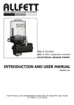
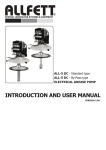
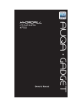
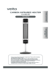
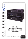
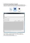
Centralized Lubrication Systems & Equipment LUBMATIC Mini DC Timer ELECTRICAL LIQUID GREASE & OIL PUMP INTRODUCTION & USER MANUAL Pleace read before using the product YEARS WARRANTY THE PHYSICAL LIFE DETERMINED BY MINISTRY OF INDUSTRY AND TRADE OF TURKEY IS 10 YEARS. PRODUCT DESCRIPTION LUBMATIC Timer DC series pumps are piston type centralized lubrication system units for oil and liquid grease (NLGI 0000) running with DC voltage. Pump elements on aluminium body generate pressure for the lubricant. Reservoir is made by transparent polycarbonate to be able to control the oil level easily; oil level controlled by low level indicator also. There is a by-pass system on pump which allows to be used by-pass type distributors. Timer type LUBMATIC pumps have electronic control card to adjust waiting and working time periods between 1 second to 99 hours. With this control card low level signal and alarms can be monitored. GENERAL SPECIFICATIONS Motor Type Working pressure Max. pressure Protection class Lubricant type Displacement Working temperature Reservoir capacities : : : : : : : : 24 V DC 20 bar. 100 bar. IP 54 Oil - Liquid grease (NLGI 0000) 345 cm³ / minute -25°C +80°C 1,5 Liters 195 265 Figure 1 152 162 1 PRODUCT COMPONENTS AND OPTIONAL EQUIPMENTS Figure 2 Product components 9 1 2 3 10 4 5 11 6 12 7 13 8 14 1. Electronic control panel 2. Electronic control box 3. Electrical connection socket 4. Filling cover 5. Connection coupling 6. Control box coupling 7. Assembly holes 8. Pump cover 9. Lubricant rezervoir 10. Security valve 11. Connection nuts 12. Filling filter 13. Pump body 14. Pump elements 15. By-Pass 16. Pump body cover 17. Low level indicator 2 ELECTRONIC CONTROL CARD PROGRAMMING INSTRUCTIONS Figure 3 Electronic control panel Time unit leds Second digit First digit Yellow led Green led Red led 1 . Press SERVICE button twice to start programming. After pressing, FIRST DIGIT of program display will start to flash and GREEN LED will be light up. WORKING TIME PERIOD will be adjusted first ; Working time periods can be chosed from 1 second to 99 minutes. 2. Press the ADDITIONAL CYCLE button untill the number you want to adjust be appears on first digit on program display. Stop pressing until number you need is appeared. Press only once to SERVICE button for control card memorize your choise and go to next digit. Press the ADDITIONAL CYCLE button again untill the number you want to adjust be appears on second digit on program display. Stop pressing ADDITIONAL CYCLE button until number you need is appeared. Press only once to SERVICE button for control card memorize your choise. One of the time unit leds will start to flash that means time unit will be selected. Press the ADDITIONAL CYCLE button untill the unit you want flashes. Press only once to SERVICE button for control card memorize your choise and go to next step. Working time period is memorized by control card. 3 3. After pressing SERVICE button, FIRST DIGIT of program display will start to flash and YELLOW LED will be light up. WAITING TIME PERIOD will be adjusted ; Waiting time periods can be chosed from 1 second to 99 hours. 4. Press the ADDITIONAL CYCLE button untill the number you want to adjust be appears on first digit on program display. Stop pressing until number you need is appeared. Press only once to SERVICE button for control card memorize your choise and go to next digit. Press the ADDITIONAL CYCLE button again untill the number you want to adjust be appears on second digit on program display. Stop pressing ADDITIONAL CYCLE button until number you need is appeared. Press only once to SERVICE button for control card memorize your choise. One of the time unit leds will start to flash that means time unit will be selected. Press the ADDITIONAL CYCLE button untill the unit you want flashes. Press only once to SERVICE button for control card memorize your choise. WORKING and WAITING time periods are memorized by control card. Electronic control card will start from working time period you chosed. If ADDITIONAL CYCLE button is pressed for 2 seconds while control card operating, waiting or working times which is on will be shown as counting down on program display. WARNINGS 1. While programming the time periods on the card memory, the time interval for touching the sections must be in 20 seconds. If 20 second is passed without touching, electronic control card exits from the program menu and operations before you did will not be allowed. In this case, card will start to operate with last succesfull programming values. 2. In case of power breakdown while pump runs at waiting or working time periods, control card will remain its position before breakdown and resume after power comes. Power breakdown does not make any change on the structure of the previous program. 3. In case of foult coming from motor or control card, please contact with ALLFETT servise. Motor cover must not be opened. 4 ELECTRICAL CONNECTION Transformer from 220 V AC to 24 V DC is needed if there is no 24 V DC source and it should be minimum 5A. SOCKET CONNECTION 2 1 1 : 24 V DC (+) 2 : ALARM : 24 V DC (-) PACKING & TRANSPORTATION All ALLFETT systems are packed with support material to reduce any harm to your mechanic and electronic equipment. But the packages must caried carefully by considering a posibility of a damage. DANGEROUS OR HARMFUL CONDITIONS TO ENVIRONMENTAL AND HUMAN HEALTH DURING USE All ALLFETT systems are producing according to relevant provisions of security regulations. There is no risk for environmental and human health during use. SERVICE STATION 5 Telephone : +90 212 501 32 01 (PBX) Fax : +90 212 501 33 37 www.allfett.net [email protected] PUMP MAINTENANCE INSTRUCTIONS 1. Pump is not working ; a. Electrical connections of the pump may be loosen or broken. Check the electrical cables and connections of the system. b. The voltage connected to pump could be different then 24 V DC. Be sure that the connected voltage is 24 V DC. c. Positive (+) and negative (-) poles could be connected wrong. Be sure that the electrical connection is done according to ELECTRICAL CONNECTION section. d. Lubricant reservior could be empty and the pump could be on alarm mode. Please fill up the pump. 2. Pump is working but not delivering grease : a. At least one lubrication point might be blocked and lubricant is coming continuously from security valve. Check all lubrication points for blockage. b. Pump element might have air because lack of lubricant. For removing air from pump element disassemble the lubricant output from pump. Run pump until you see lubricant coming without air bubbles. When lubricant continuously goes out and doesnt have air in it stop the pump and re-assemble the lubricant output to pump. QUALITY SYSTEM ISO 9001 BUREAU VERITAS Certification This product is produced by ALLFETT Mekanik ve Elektronik Sistemler San. Tic. Ltd. Sti. company, which, is certificated by Bureau Veritas with 30093 number of certificate to compatible for ISO 9001:2000 standard and owner of the quality / environment management system N° 30093 6 RULES TO COMPLY WHILE USING AND WARRANTY CONDITIONS 1 Damages occur while additional transports after delivering the goods from ALLFETT to the customer, ARE NOT COVERED UNDER WARRANTY SCOPE. 2 Pumps are produced to lubrication purpose and are not convenient to work more than 2 hours continuously. Working continuously under maximum pressure will harm the system. Damages occur from this reason ARE NOT COVERED UNDER WARRANTY SCOPE. 3 Washing of the pump with pressured water causes damages. Damages occur from this reason ARE NOT COVERED UNDER WARRANTY SCOPE. 4 Pump reservoir is made of translucent material in order to see the grease level from outside. For this reason, painting of any part of the pump is not adviced. Painted parts ARE NOT COVERED UNDER WARRANTY SCOPE. Using ALLFETT low level indicator is a reliable system to control the grease level. 5 Pumps have an electric driven motor and must fed from an appropriate electric source and electrical connections must be done properly. 6 Keeping an uncovered cable during system assembly, electric connections may cause fatal damages on systems in which high voltage is turned to low voltages. Cables must be installed properly and electric attack risk must take into consideration. 7 Damages coming from low or high voltage, wrong electric installation, using a different voltage from products definition ARE NOT COVERED UNDER WARRANTY SCOPE. 8 Transformer from 220 V AC to 24 V DC is needed if there is no 24 V DC source and it should be minimum 5A. 9 Check the lubricant properties you will use in the pump to see appropriate classes. (Use NLGI 000 for liquid grease) 10 Lubricant will be used in the system must certainly be clean and any foreign material must not enter while filling. 11 If the pump is working out of lubricant pump will try to send air to the points instead of lubricant and points will not be lubricated. Damages on pump and on the system coming from that reason ARE NOT COVERED UNDER WARRANTY SCOPE. 7 12 Because of there is an electrical control card inside motor cover, using high frequency wireless cominication devices 1 meter distance from the pump may couse malfunction. Damages occur from this reason ARE NOT COVERED UNDER WARRANTY SCOPE. 13 Electronic control card works between 10 to 30 Voltage. Although there is a protection against high voltage, control card may be broken from high voltage. RULES TO COMPLY WHILE USING AND WARRANTY CONDITIONS 14 If pump connected to power sources like generator, regulator must be used after transformer. 15 Disassembly or loosen any part of the pump while working is not allowed.Do not take off the top cover to fill reservoir. Damages on pump and on the system coming from those reason ARE NOT COVERED UNDER WARRANTY SCOPE. 16 Damages occur while fixing the pump by unauthorized staff ARE NOT COVERED UNDER WARRANTY SCOPE.Except the conditions mentioned in PUMP MAINTENANCE INSTRUCTIONS consult the technical service or leave the maintenance to technical service. 17 SERVICE STATION Telephone : +90 212 501 32 01 (PBX) Fax : +90 212 501 33 37 www.allfett.net [email protected] 8 WARRANTY Utilisation of this warranty certificate has been permitted by The Republic of Turkey, The Ministry of Industrial and Commerce, The general Administration of Protection of Consumer Right and Competition, in accordance with the law numbered 4077 . PRODUCER COMPANY NAME : CENTRAL ADRESS : TELEPHONE FAX : +90 212 501 32 01 (PBX) : +90 212 501 33 37 AUTHORISED PERSON SIGN - STAMP : PRODUCT TYPE BRAND MODEL SERIAL NUMBER DELIVERY DATE / PLACE WARRANTY REPAIR TIME : : : : : : : Electrical oil and liquid grease pump ALLFETT LUBMATIC Mini DC Timer SALER COMPANY NAME CENTRAL ADRESS TELEPHONE FAX BILL DATE / NR. : : : : : ................................... ................................... ................................... ................................... ................................... 9 ................................... ................................... 2 Years 30 days WARRANTY CONDITIONS 1. The warranty period is two years from the date of delivery. 2. The product including all its components is under the warranty of our company. 3. In case of defects within the warranty period the period spent in repairing is added to the warranty period. The repairing period is maximum 30 days. This period starts from the date of delivery of the product to the services centers or to the seller, the agency the representative, the importer or the manufacturer of the product respectively, in case there are service centers. 4. In case the product has material, workmanship or manufacturing defects, the product will be repaired free of charge and expenses of any sort including labor, the value of the parts replaced or any our charges. 5. The product will be replaced free of charge; - If the product permanently disfunctions due to repeating the same defect more than four times within the warranty period - If the maximum period for repairing is exceeded. - If it is determined that the defect cannot be repaired by report written by the service, or in the absence of service centers, by the seller, agency, representative, importer or manufacturer of the product respectively. 6. The present warranty does not cover damages resulting from importer handling by deviating from the instructions in the manual. 7. General administration of protection of consumer rights and competition in the ministry of industry and commorce may be applied for problems concerning the warranty certificate. 10