1
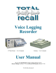
Tele Corder
TCwL-B4
Voice Logging
Recorder
Tele Corder
Four Channels — Internal Hard Drive stores the most recent 11,000
Conversation Hours — Access recordings via USB & LAN
User Manual
Version 2.42-B-USA
Table of Contents
Page 1
Tele Corder Model TCwL-B4 — Description ................................... 3
Recorder Features .............................................................................................. 3
Supplied Accessories......................................................................................... 3
1.
Identify the Front and Rear Panel Connections.............................. 4
2.
Installing PC Software and Connecting to a PC ............................. 4
2.1
2.2
3.
Install Software onto the PC................................................................. 4
Connect Power Supply and USB Cable ............................................... 5
Setup via USB Connection to PC ...................................................... 5
3.1
3.2
3.3
3.4
3.5
3.6
Open Software ...................................................................................... 5
Recording Process ................................................................................ 5
Setting for Phone Line or Voice Activated Recording......................... 6
VAR Settings (Voice Activated Recording) ........................................ 6
Setting Channels for Operation in VAR Mode .................................... 6
Configuring TeleCorder using a PC.................................................... 6
3.6.1 Hardware Information............................................................ 7
3.6.2 Date/Time Setting .................................................................. 7
3.6.3 Channel/Port Setup .............................................................. 7
3.6.4 VAR Voltage Threshold (Voice Activated Recording) ....... 7
3.6.5 VAR Turn Off Delay Time .................................................. 7
3.6.6 VAR Time Out....................................................................... 7
3.6.7 Save Recordings Less Than 8 Seconds.................................. 8
3.6.8 Audio Recording Mode (Quality of Recordings)................... 8
3.6.9 Limitation for List Displaying ............................................... 8
3.6.10 Caller ID Detection Settings ................................................. 8
3.6.11 About TeleCorder PC Software........................................... 8
3.6.12 Quit........................................................................................ 8
3.6.13 Notes ..................................................................................... 8
4.
Connecting to Phone Lines and other Audio Sources .................... 9
5.
Setup for Accessing the Tele Corder via LAN.................................. 9
5.1
6.
Reflash Utility Application to Find or Change IP Address ............... 9
5.1.1
Reflash Utility Application Notes ................................ 11
Using the Tele Corder ....................................................................... 12
6.1
Managing and Playing the Recordings with a PC ..............................
6.1.1 Using the Utility Software.................................................
6.1.2 Auto Refresh the List of Recordings .................................
6.1.3 Port Monitoring and Listening to Live Recordings...........
6.1.4 Refreshing the List of Recordings .....................................
6.1.5 Re-Order the List of Recordings .......................................
6.1.6 Find Recordings Using Search Criteria .............................
6.1.7 Files, Wav Conversion, Print List, and Delete ..................
6.1.7.1 Conversion to Wav Files................................
TeleCorder V 2.42, TCwL-B4-USA
12
12
13
13
13
13
14
14
14
1
6.1.7.2 Browse to Select Folder Where Files will be Saved ......... 14
6.1.7.3 Convert/Copy All Recordings......................................... 14
6.1.7.4 Convert/Copy Recordings from Last Month .................. 15
6.1.7.5 Convert/Copy Recordings from Last Week.................... 15
6.1.7.6 Help for Converting Recordings to Wave Files.............. 15
6.1.7.7 Use Fast Mode when Converting Files ........................... 15
6.1.7.8 Convert/Copy Recordings by Range of File Numbers ... 15
6.1.7.9 Volume Balance Setting (DAVA) .................................. 15
6.1.7.10 Print and Save the List of Records.................................. 15
6.1.7.11 Delete Recordings ........................................................... 15
6.1.8
Information and Settings ................................................................ 16
6.1.8.1 Hardware Information..................................................... 16
6.1.8.2 Date/Time Setting ........................................................... 16
6.1.8.3 Set Channels to VAR Mode............................................ 16
6.1.8.4 VAR Voltage Threshold ................................................. 16
6.1.8.5 VAR Turn Off Delay ...................................................... 17
6.1.8.6 VAR Time Out................................................................ 17
6.1.8.7 Save VAR Recordings Less than 8 Seconds................... 17
6.1.8.8 Recording Mode (Recording Quality) ............................ 17
6.1.8.9 Limitation for Recordings Displayed in the Listing ....... 17
6.1.8.10 Caller ID Detection Settings ........................................... 17
6.1.8.11 About TeleCorder PC Software....................................... 17
6.1.8.12 Quit Setup Window........................................................... 17
6.1.9 Security (Password – Lock/Unlock) ................................................ 18
6.1.9.1 Modify Password ............................................................ 18
6.1.9.2 Setting Password for LAN and/or USB Access.............. 18
6.2
Play Recordings from List ....................................................................... 19
7.
Guarantee & Liability ...................................................................... 20
8.
Specifications ..................................................................................... 20
9.
Contact Information for Support and Service............................... 21
10.
Notes ................................................................................................... 21
11.
User Notes .......................................................................................... 21
12.
Popular Accessories .......................................................................... 22
TSA-3LM
TSA-SLM
TSA-2A1
RSA-U5
MOD-SC
2
Adapter for Connecting to a Phone Set at Handset Jack.......... 22
Adapter for Connecting to a Phone Set, with On/Off Switch... 22
Adapter for Connecting to a Phone Set, with Audio Mixer ... 22
Radio Adapter, with Amplifiers, Mixing, and PTT Sensing... 22
Adapter for Converting Modular Phone Plug to Mini Plug...... 22
TeleCorder V 2.42, TCwL-B4-USA
TeleCorder
Voice Logging Recorder — Model TCwL-B4
The TCwL-B4 TeleCorder can simultaneously record analog audio from up to four phone lines
or other line-level audio sources. Recordings start and stop automatically using either phone line voltage
sensing or audio activation. It has an internal hard drive where the most recent 11,000 hours of recordings
or 65,000 digital call files are stored. When the maximum capacity is reached, it continues documenting
new conversations by overwriting the oldest recordings.
While the TCwL-B4 records as a stand alone unit, connection to a PC using the supplied USB cable
and software (Win-2000/XP/Vista/Win-7) is required for initial set-up. Recordings are accessed via a PC
using a USB or LAN connection to the recorder for playback. Recordings can also be copied from the
recorder to your PC using the USB or LAN connections.
We recommend that all sections of this manual be read prior to installing the recorder. This manual
and the software supplied with the recorder are only for use with the TeleCorder model TCwL-B4.
Features include:
9
9
9
9
9
9
9
9
9
9
9
Easy installation and administration
Small footprint makes it easy to place in any location
Internal 2.5" HDD capable of holding 11,000 hours of call data and up to 65,000 calls
Search via Port #, Caller ID #, Dialed #, and Date
Copy recorded files to your PC as .UPx or standard .WAV files
User access to recordings and call data via USB and LAN (network)
Master Recorder , Master LAN, PC LAN, and PC USB password protection of data
Software can be installed on multiple PC’s
Support for Ethernet (10Mbps) or Fast Ethernet (100Mbps)
Port Monitoring and Listening via LAN
After the recorder is installed, it is always monitoring inputs and recording when activity is
present. The software does not have to be open on a PC for it to function as a recorder. The
PC software is only used for setup, playback of recorded conversations, searching calls, and
copying recordings to the PC. The TCwL-B4 recorder does not rely on the PC for recording.
9 The recorder uses software on a PC as the interface to search and play back calls. If connected
to a network (LAN), the unit can be placed in an equipment room or a supervisor’s office to
prevent tampering. All you need is power, a connection to the network, and access to the
equipment you need to record (phone lines, telephone handset audio, two-way radio audio, etc).
TCwL-B4 Recorders distributed by Omnicron Electronics are supplied with the following items:
9
9
9
9
9
9
9
9
9
TCwL-B4 recorder
Owner’s Manual
Software CD
USB cable
LAN cable
110 volt AC to +5 volt (2 Amp. regulated) DC power supply
Four # T-18 (18' phone cable and “T” adapter)
Two # MTJ-S2 (converts dual line jacks to two single line jacks)
Master Password (keep in a secure place)
If any of these items are missing contact your place of purchase.
If you purchased optional items such as cables and/or adapters for installation to audio sources that
do not terminate in line level audio at standard RJ-11 phone jacks, see the instructions that were provided
with the optional accessories for additional installation and operation procedures.
TeleCorder V 2.42, TCwL-B4-USA
3
1. Identify the Front and Rear Panel Connections
Unpack and check the contents of the TeleCorder package. Locate the master password page and keep it in
a secure place.
Front view — top bar has LED’s that light to indicate power, HDD, and channel status.
Rear view — RJ-45 LAN jack for connecting to a computer network, USB jack
for connecting to a computer via USB, red LED to indicate an active 100Mbps LAN
connection, green LED to show LAN activity, two modular phone jacks for connecting
to the source of the conversations to be recorded (two channels per jack, image at right),
and +5vDC input jack for connecting to power using the supplied AC adapter.
2. Installing PC Software and Connecting to a PC (Win-2000/XP/Vista/Win-7)
Install TeleCorder software from the CD included with your recorder prior to connecting the
supplied USB cable from the recorder to the USB port on your computer.
2.1 Install Software onto the PC
If the recorder software is being installed on a multiple user PC, the installation directory should be a
shared location or the “All Users” directory if you wish to allow access by all users. If connecting a
TeleCorder to a PC that was previously used with a different version of TeleCorder software, you should
remove the old TeleCorder program (PC Control Panel – Add/Remove Programs) prior to installing the
new software.
Also see “Read-Me” notes on software CD for additional information and for a software tool that
permits older recorders to be used with a 64-bit PC (TCwL-B4 recorders that did not come with V2.42).
Insert the CD into the drive on your PC. If it does not auto run to show install procedure, look at files on
the CD using file manager and open “SetupTeleCorderV242_StdEN.exe” (Win-2000 through Win-7).
Follow on screen instructions.
The TeleCorder program will now be installed in your computer. It will be listed under
Programs, be listed in Control Panel add/remove programs, and if you also installed the
Reflash Utility there should be an icon on your desktop for the TeleCorder software (image at
left) and a Reflash Utility icon (image at right) for the program that is used to set up access to
the recorder via LAN.
If the PC will be used for configuring the recorder for LAN access, install or copy the Reflash Utility
file “TCwL_Reflash” from the software CD to your PC desktop (icon at right). Follow the instructions in
Section 5. for LAN setup using the Reflash Utility.
4
TeleCorder V 2.42, TCwL-B4-USA
For increased security and to prevent tampering via LAN, a USB cable connection to a PC is required
for administration of hardware settings. All hardware settings, such as the selection of voltage
sensing or audio activation (VAR), VAR sensitivity, VAR turn-off-delay, and VAR maximum
call length, are done only via USB. Network settings are done using the “Reflash Utility”.
2.2
Connect Power Supply and USB Cable
Plug the supplied 5 volt power supply (photo at right) into a standard 110v
AC outlet and connect its output cable to the DC+5V jack on the back of the
recorder. A blue LED on the front of the recorder will indicate that power is
connected. It can take up to 30 seconds to boot-up. There are LEDs on the front
of the recorder that will indicate recorder activity, including one for each of the
four channels.
Connect the supplied USB cable (photo at right) from the USB port on the
back of the TeleCorder to a USB port on your computer. If the software was
previously installed, the first time you connect the TeleCorder to your computer
your PC should display a “New Hardware Found” message, search for and install
the required driver software (FTDI20600.dll). Select “Continue” to install the
driver.
If connecting a TeleCorder to a PC that was previously used with a different
TeleCorder product, you have to remove the previous software and .dll files
before connecting. Go to PC Start Menu > Control Panel > Add or Remove Programs. Look for the .dll
file name FTD2XXX and remove it. Then scroll down to TeleCorder software and remove it. Now you are
ready to install the new software and drivers.
You may receive a pop-up message telling you that it has “Found New Hardware, FT8U2XX_1.dll
device, installing Files Needed”, type the path to the folder where the driver was previously installed (such
as: C:\Program Files\TeleCorder\TeleCorder\TeleCorder.exe), or the path to the driver folder on the CD
supplied with your TeleCorder (such as: E:\Driver, where E is the CD drive on your PC containing the
TeleCorder CD).
3. Setup via USB Connection to PC
3.1
Open Software and run the TeleCorder program by clicking on the
icon on your PC desktop
that was created when the program was installed or from the Start/Programs list if the icon is not on your
desktop. If more than one TCwL-B4 is found, select which one to access (maximum of four, one at a time).
3.2
Recording Process
When connected to standard telephone lines, the TeleCorder will automatically record the telephone
number called in or dialed out, time duration of the call and the voices of the conversation. You don’t need
to change your procedure for making or receiving your calls. Nevertheless, the following points should be
considered. When connected to phone lines, channels should be set to start/stop recording using the voltage
sensing mode, not the VAR mode (hardware set-up from Hardware screen using a PC via USB
connection).
If Caller ID numbers are not displayed, confirm with your telephone company that your phone lines
have the caller ID feature enabled. Otherwise, there will not be caller phone numbers recorded and
displayed when managing the recordings. If you are connected to telephone handset audio, the recorder will
not show caller numbers and will only show dialed out numbers if the handset has standard DTMF tones
when dialing. Also check to be sure phone line channels are set for voltage sensing, not for VAR start/stop.
Always wait to answer a call until after the second ring so that the phone number from the calling party
can be received and stored with the recording.
When channels are set to start and stop recording using voltage sensing, outgoing calls will not be
saved unless they are longer than 8 seconds and contain a minimum of 3 dialed digits (DTMF tones). This
feature minimizes false recordings and does not apply when using Voice Activated Recording (VAR).
TeleCorder V 2.42, TCwL-B4-USA
5
3.3
Setting for Phone Line or Voice Activated Recording (VAR)
When you first connect a new TeleCorder, default settings for all channels will be for Voice
Activated Recording (VAR). Channels connected to phone lines should have their start/stop mode changed
to the voltage sensing start/stop mode. In this mode, instead of monitoring audio levels, the recorder will
monitor for DC voltages on the selected inputs to indicate on-hook and off-hook status. The phone line
voltage is high when the circuit is not in use and will drop to a lower voltage when it is being used. Any
channels set for on-hook/off-hook voltage sensing that are not connected to a phone line will not show any
recordings due to the lack of the DC voltage changes that are required to initiate a recording in this mode.
If you connect any of the TeleCorder inputs to audio sources that do not have standard on-hook/offhook voltages, these channels must be set for audio or voice activated recording (VAR).
3.4
VAR Settings (Voice Activated Recording)
Recorder channels set for the VAR mode will detect the voice level on the line to start a recording. It
will start recording when a preset audio level is reached (normal conversation levels), and stop after the
audio drops below this threshold (no sound other than weak background noise) for a preset period of time.
The length of quiet required for the recording to end is called “turn-off-delay”.
Phone Line Recording
Voice Activated Recording (VAR)
Requirement
to Start
Phone Line DC voltage lower
than the threshold (<20v DC)
Audio level on input is loud enough or louder than
preset threshold required to start recording
Requirement
to Stop
Phone Line DC voltage higher
than the threshold (>20v DC)
Audio level is lower than preset level required to
continue recording for the selected turn-off-delay
Recording from standard
Analog phone lines
1. Radio recording, broadcast or two-way
2. Amplified microphone
3. Audio picked up from handset or headset of
analog or digital telephone set (single or multiline phone)
4. Analog phone line recording where DC voltage
sensing cannot be used
Suggested
Uses
Parameters
3.5
1. DC Voltage Threshold:
(This threshold is preset in the
TeleCorder through hardware
components and cannot be
changed via software).
1. VAR or Off-Hook Mode for each channel
2. Threshold in 4 levels
3. Turn-off-delay/VAR space: (4, 12, 32, or 100
seconds)
4. VAR Time-Out to limit long recordings and start a
new recording: (20, 40, 60, or 80 minutes)
Setting Channels for Operation in VAR Mode
Use your PC to configure the TeleCorder to select Phone Line recording or VAR mode, and to
change and confirm these and other operating parameters.
3.6
Configuring TeleCorder using a PC
Using your PC with the TeleCorder program running, select Info & Settings from the main
screen. You will open the Hardware Information & Settings screen as shown on the next page.
From this screen, you can change hardware settings that will be stored in the recorder and, by selecting
Hardware Information, view additional information about the recorder including version number,
capacity, media usage, recorded call items, deleted call items, etc.
6
TeleCorder V 2.42, TCwL-B4-USA
3.6.1 Hardware Information: Click on this box to show information about your TeleCorder :
hardware version, model type, number of calls recorded, number of calls deleted, total length of all
recordings (in hours, minutes and seconds), total length of deleted recordings, and percentage of storage
space used. Information displayed for number of files and duration is for files shown on the current list
on the PC.
3.6.2
Date/Time Setting: Click on this box to copy the date/time setting from your PC to the TeleCorder.
3.6.3 Set Channels to VAR mode instead of voltage sensing mode used for phone line: Each channel
(Port) in the recorder can be set to start and stop recording using either audio activation (VAR) or voltage
sensing. Channels showing a check mark in the boxes labeled Port 1, Port 2, Port 3, or Port 4, are set for
VAR recording. Channels with no check mark indicate they are set for phone line recording. For any
channel you want to start/stop recording using the phone line voltage sensing mode, click on the box for
that channel to remove the check mark, then click the Write Hardware button to confirm any changes.
3.6.4
VAR Voltage Threshold: Set the threshold level to match the audio level on your audio source.
L0: Extra Sensitive, suitable for weak audio sources with low background noise level: (for
example, with weak earphone or line-out recording).
L1: High Sensitivity, suitable for normal line level audio sources with low background noise
levels: (normal phone handset earpiece audio or weak speaker of radio).
L2: Mid Sensitivity, suitable for higher than normal audio levels and/or higher background noise
levels: (for recording from a noisy phone line when voltage sensing cannot be used due to nonstandard voltages or with normal speaker audio from a radio).
L3: Low Sensitivity, suitable for very high audio levels, and high background noise levels.
Recording may stop if audio levels are too weak: (phone recording with non-standard and very
noisy DC voltages, or extra loud radio audio).
After making changes, click the button labeled Write Hardware to confirm any changes. You may be
asked to quit the program and try again. You may also need to un-plug and re-connect the TeleCorder
power or USB cable to successfully change the TeleCorder operating parameters.
3.6.5 VAR Turn Off Delay: If any channels have VAR selected for recording start/stop, also select one
of the four turn off delay options (VAR Turn Off Delay): 4, 12, 32 or 100 seconds. This setting will help to
prevent recordings from ending during quiet periods. Click the Write Hardware button to confirm changes.
3.6.6 VAR Time Out: If any channels have VAR selected for start/stop, set the time out to one of the
four choices: 20, 40, 60 or 80 minutes. This setting will limit the maximum length of a recording for easier
management of long conversations or for when recording from broadcast radio where pauses may not be
long enough to separate individual recordings using VAR for start/stop. If a recording reaches the
TeleCorder V 2.42, TCwL-B4-USA
7
maximum length of time that you select for VAR Time Out, that recording will end, and a new recording on
that channel will begin. Click the Write Hardware button to confirm any changes.
3.6.7 Save VAR and Outgoing Calls Less than 8s or Outgoing Calls with Less than 3 DTMF Codes:
Click on this option to place a check mark in its box if you want to save recordings that are less than 8
seconds long. If this box is not checked, VAR recordings shorter than 8 seconds, and outgoing telephone
calls (using voltage sensing for start/stop) with less than 3 DTMF digits, will not be saved.
This setting is normally used if external noise causes frequent and unwanted false audio activated
recordings, or if telephone line testing produces short off-hook conditions that are not associated with actual
phone line usage. It is normal to record all activity on the monitored circuits. Use care when setting to delete
short recordings.
3.6.8
Audio Recording Mode: From this sub-button you can set the quality of recordings.
Mode 0 --- Large file, good audio.
8bit linear PCM mode.
Mode 1 --- Tiny file, poor audio.
2bit ADPCM mode.
Mode 2 --- Small file, good audio.
3bit ADPCM mode. Default mode set from factory.
Mode 3 --- Large file, best audio.
8bit nonlinear PCM mode.
3.6.9
Limitation for List Displaying: From this sub-button, you can set the list display features to
speed up the list refresh process or to have more items displayed in the lists of recordings shown on your
PC in the main TeleCorder program screen. The default setting is 2000 for fastest speed. You can select a
different number, such as 10000, 32768 or 65536, respectively. This selection is saved in software, not as a
hardware setting and will be reset to 2000 when the software is closed and reopened.
3.6.10 Caller ID Detection Settings: From this sub-button you can set (turn on/off) the caller ID
detection features.
Pre-Ring DTMF Detection: If the local caller ID mode is DTMF and sent before the ring, you
must turn this feature on. Otherwise, if erroneous caller numbers are
sometimes received, you should turn this feature off.
Pre-Ring FSK Detection: If the local caller ID mode is FSK and sent before the ring, you must
turn this feature on. Otherwise, if erroneous caller numbers are sometimes
received, you should turn this feature off.
Forced FSK Between Rings: If your caller ID signaling is FSK and sent between the rings, you
must turn this feature on. This is the normal setting for North America.
3.6.11
About TeleCorder PC S/W: From this sub-button, you can see additional information about the
software supplied with the TCwL-B4 recorder.
3.6.12
QUIT: Use this sub-button to exit the Hardware Information & Settings window.
3.6.13
NOTES:
1. The above settings must be locked into the TeleCorder hardware by restarting the recorder.
After any of the above settings are changed, they will not take effect until the recorder is restarted
by turning off or disconnecting AC power to the TeleCorder, waiting a minimum of ten seconds,
and powering the TeleCorder back on. Any changes made in software should now be locked into
the recorder’s internal memory.
2. To avoid interruption of active recordings, you should only set the above items while the
recorder is idle. Wait until no channels are active or unplug inputs prior to changing settings.
3. After the settings have been changed, check to make sure that the recorder is functioning as
expected.
4. The recorder listens for outgoing numbers dialed using DTMF/touch-tone signaling and stores
them with the recording. It is possible for it to document and record false phone numbers when
8
TeleCorder V 2.42, TCwL-B4-USA
the recorder is in the VAR mode (particularly when recording broadcast radio music where the
audio can mimic sounds of dialing). To avoid collecting and recording these erroneous numbers,
you can use the PC interface to disable storing of dialed digit signaling.
4. Connecting to Phone Lines and other Audio Sources
TeleCorder inputs require 2-wire analog audio such as from direct connection to analog phone lines,
two-way radios, amplified microphones, telephone handset or headset audio (analog or digital phones,
using direct connection to earpiece audio or optional TSA-3LM or TSA-SLM adapters), etc.
The TeleCorder connects in parallel to your audio sources. There are two modular phone jacks on the
back labeled PHONE. Each modular phone jack has connections for two phone lines or other audio sources.
When looking at the back panel, the jack on the left is for Ports 1 and 2, the jack on the right is for Ports 3
and 4.
The modular jacks use pins 3 & 4 for the first input
(center pair), and pins 2 & 5 for the second input (see the
drawing at left). Each individual input can be referred to as
either a Channel or Port.
Connect audio sources for channels one and two using
the left jack, and channels three and four to the right jack in
a similar manner.
The TCwL-B4 is supplied with two of the MTJ-S2
splitters (see photo at right) to provide individual jacks for each input if you are not
using phone cables with two lines.
Four T-18 cable sets (18' phone line cable with “T” adapter, photo at left) are also
supplied with the recorder. You can use these or other suitable cables to connect to your phone lines or
other audio sources to the recorder.
If it is not convenient or possible to install using standard
modular jacks, identify the pair of wires for each line or audio
source and connect in parallel to each individual input on the
TeleCorder.
With bundled phone wiring, you must first identify the
line pairs among the wiring cables and then connect the wires
from the TeleCorder inputs to these pairs. Equipment and wiring diagrams may be required to expedite
proper installation. Check with your phone or wiring provider for assistance as needed.
If you wish to record from multiple line analog phones or digital telephone sets, instead of individual
phone lines, the most popular way to connect is with a handset splitter. The handset splitters (such as the
Omnicron TSA-3LM, TSA-2A1, or TSA-SLM) are available from your TeleCorder representative. Your
sales representative can also assist you in selecting other cables or adapters to simplify installation for your
application.
5. Setup for Accessing the Tele Corder via LAN
After installing the TeleCorder software onto a PC, use the software to configure the recorder,
connecting the recorder to your phone lines or other sources of conversations and confirming that it
is functioning properly. You are ready to use the Reflash Utility to setup access to the recorder from
a network (LAN).
Connect the LAN cable to a network switch or to the LAN port on the back of your PC and
then to the LAN port on the TCwL-B4. Check to see that the cable connection indicator (RED) LED
and activity (GREEN) LED are lit on the back of the unit. Then proceed to run the Reflash Utility.
5.1
Reflash Utility Application to Find or Change IP Address
With the recorder connected to your network or LAN port on a PC, open the
“TCwL_B4” Reflash
Utility that was installed onto your PC earlier (Section 2.1) to find the unit on the network connection. The
TeleCorder V 2.42, TCwL-B4-USA
9
initial IP of TCwL-B4 is set as "192.168.0.200". If the IP segment of your network is within the same range
(“192.168.0.*”) it should be found by your PC. Be patient, this may take some time (many seconds). If
more than one TCwL-B4 recorder is connected to the same LAN, the IP addresses must be different.
Select Find the Device Over the LAN. It will display the factory set
IP address on the screen when it is found by the Reflash Utility application.
If the TCwL-B4 cannot be found via the LAN, the IP address of the unit can be entered into the
“Connect Directly Using Above IP” box to search for the specific IP address. If your IP address range is
within the default range of the unit you will not need the USB connection to access the TCwL-B4.
10
TeleCorder V 2.42, TCwL-B4-USA
If the TCwL-B4 cannot be found via the LAN, connect a USB cable between a PC and the back of the
TCwL-B4 recorder, then run the Reflash Utility (V1.3) and edit the device settings. When finished, be sure
to click on the Change Device Settings button. To lock the new settings into memory, power must be
cycled (power the recorder down and up).
When done, disconnect the USB and run the Reflash Utility again. When the Reflash Utility finds the
device, you are ready to run the TeleCorder software and access the recorder via the LAN connection.
When the Reflash Utility V1.3 is open and the device is found over the LAN, port settings can be
changed using the Reset by IP command. Find the device over the LAN, make your setting changes, select
the “Reset by IP” button then select the “Change device Settings as wanted” button. Close the SW and
reopen to verify changes.
5.1.1 Reflash Utility Application Notes (Version 1.3):
TCwL-B4 can be connected via USB or LAN. The utility will check TCwL-B4 from USB at boot stage
automatically (first). If no USB is detected, you can force it to search TCwL-B4 over the LAN via the Find
the Device Over the LAN button. The device default IP will have to be within the same range as the
network for this to work.
The Direct IP input field for direct connection and setting can be used if the device is not found over the
LAN. Enter the IP and select find.
If you have a problem reading the device, you may check the right-bottom corner box to Load default
settings file (factory defaults).
When the device is successfully found, you can read the existing settings information from the device.
All these settings are copied into the Wanted settings fields. Edit these as necessary for your application.
.F/W Version:
ex. TCwL4.02.
.Existing IP:
ex. 192.168.0.200.
.Subnet Mask:
ex. 255.255.255.0.
.Existing MAC:
ex. CD.16.76.5F.8E.A5.
.Port TC Access:
ex. 2008.
.Port UP Stream:
ex. 2009.
.Handy Player Support: Yes or No. This feature is not supported with TCwL-B4, default is NO.
.Existing TCwL ID:
ex. TCQV62SF. This ID is set to be as same as the USB TC ID.
nd
.Existing 2 Password: The 2nd password created by the user can be used to unlock access to the
LAN as well as the Master Password (original TCwL-B4 ID) if it is locked (password protected).
.LAN Access Locked:
Yes/No. Select if the LAN access is password locked (protected).
When editing and testing settings is complete, you should check the box to Save default settings file to
save the default settings (as a template).
Make necessary changes for the logger’s line parameter settings (VAR modes etc.).
.Port 1-4:
Checked if VAR mode is wanted, default is audio activation.
.VAR Voltage Threshold: Define the VAR sensitivity, Levels 1-4, default is mid sensitivity (2).
.VAR Turn Off Delay:
Define time to wait for audio before turning off, levels 1-4, default is 12 sec.
.VAR Time Out:
Define the Max length of call, Levels 1-4, default is 20 min. default (0).
.Caller ID Settings:
All selected unless erratic characters result. USA standard is FSK.
.Audio Recording Mode: Recommended setting is the default, default is Small file good audio (2).
After editing, you can click the Change Device Settings As Wanted button to save the new settings
into the device.
NOTE: Be aware that the new settings will take effect after the device restart (power off and on).
TeleCorder V 2.42, TCwL-B4-USA
11
The new settings will be saved in files named TCwLSettingsDefault.ept and TCwLSettingsUser.ept.
You may load these settings back into the logger as necessary.
It is very important to check all settings before restart.
Quit this application and launch again to check and verify your settings.
NOTE: Settings can be changed via the USB or LAN connections once the unit is installed. You can force
the new settings remotely via the Reset by IP and then Change Device Settings as Wanted.
6. Using the Tele Corder
6.1 Managing and Playing the Recordings with a PC
Double click on the TeleCorder software icon
to open the program. The software will search for a
TCwL-B4 recorder connected to the PC via USB or LAN and, if a recorder is found, the software window will
display the most recent 2,000 recordings. The TeleCorder recorder software can only connect to one recorder
at a time, LAN or USB. If more than one TCwL-B4 is found, select which one to access (maximum of four).
The PC does not have to be ON or connected to the TeleCorder for it to function. Connecting the
TeleCorder USB or a LAN cable to your PC and/or turning the PC power on or off will not stop the
recorder from functioning. You can also disconnect the TeleCorder USB and or LAN cable from a PC
and connect it to a different PC or LAN connection without interrupting the TeleCorder operation. The
PC used for managing/playing must be equipped with an available USB or LAN port, sound card as
well as speakers, and use Windows® operating system (Win-2000/XP/Vista/Win-7).
6.1.1
Using the Utility Software:
You must install the supplied utility TeleCorder Manager/Player software from the provided disk
to your computer prior to being able to manage the recorder from the PC or play recordings through the
PC control (see manual Section 2). The first time that you connect your PC to your TeleCorder, you
may be asked to install the USB device driver. This driver should have been copied to your PC during
install. If not, use the CD supplied with your TeleCorder to install the required USB driver following
the instructions displayed on your computer.
After installing the software, place a short cut icon on the desktop for easy access (if it was not
automatically installed during install). Click the software icon, or the short cut created during the install,
and the recordings will be listed in the main window (as shown in the following screen image). The listed
information includes the ITEM or sequential recording number, the PORT that was the source of the
recording, CALLER # (if available when the recording was made) or DIALED # (if available when the
recording was made), DATE (mm-dd-yy) of each recording in month, day, and year, TIME the recording
started, and the DURATION of each recording in minutes and seconds.
All records are listed in the reverse order so that the most recent recording is indexed as item number 1.
You can drag the slider bar on the right side of the display window to view the un-displayed part of
the list. On the lower part of the form, there are buttons for Refresh, Re-Order, Find, Files, Info & Settings,
Security, and Exit. The recorders IP address will be displayed in the top of this window.
12
TeleCorder V 2.42, TCwL-B4-USA
The check boxes provide the following functions:
6.1.2 Auto-Refresh: When this checkbox is selected the “Recording List” display will update most
recent calls every minute.
6.1.3 Port Monitoring & Listening: When this checkbox is selected the software user can see which
channels are active, and live monitor calls as they are taking place. Click on the port you want to monitor,
headphones will appear in the port, and you will hear the call live. It will continue to monitor until the port
is clicked on to deactivate it.
The buttons provide the following functions:
6.1.4
Refresh:
Refresh the list to display the latest recordings in the TeleCorder at any time.
6.1.5
Re-Order:
User can select one of the following ordering rules to re-order the list.
1. Recorded – provides a list based on the time recordings ended.
2. Starting Time – provides a list based on the time recordings started.
3. Record Duration – provides a list based on the length of recordings.
4. Channel Number – provides a list based on the channel number.
5. Un-Answered List – provides a list of calls on phone lines that were not answered.
(Un-Answered Listing is not supported with TCwL-B4)
TeleCorder V 2.42, TCwL-B4-USA
13
6.1.6 Find:
You can search the records using a specific port/channel number, caller number or dialed
number and/or within a date and time range that you input.
In the dialogue box, you can enter search conditions such as date range, digits from a phone number
such as 010, 6256, etc. The searched results will display on the screen after you select “Start Search”.
You may also enter only a start and stop date range and all of the recorded items during the date range
will be displayed.
The recorded items after a search can be played or used for further searching and for making Wave
files in a batch job. Refer to the File Copy for more details.
6.1.7
Files:
This button provides the following functions for the displayed files.
6.1.7.1 Conversion of Recordings to WAVE or .UPx (TeleCorder) Files and Saving to PC:
Wave Files are a widely used and supported multimedia File Format for the PC and other computer
systems. Since the TeleCorder uses a unique format for saving the recordings in digital form, digitally
converting them is a better way to exchange information with other systems that do not have TeleCorder
software. You can use your PC to send audio recordings via e-mails or make backup CDs without worrying
that others may not be able to play them. .UPx files are stored in the TeleCorder format.
There is also an option to save individual recordings when they are selected for playback. Select the
button with red dot “Q” from playback menu, see section 6.2.
6.1.7.2 Browse --- Use the Browse button to select the folder on your PC hard drive where you wish to
save the copies of the recordings.
6.1.7.3 All --- Copy all of the records listed in the form, including both the ones displayed and the ones
not displayed. This button would be used to copy all recordings retrieved by a search.
14
TeleCorder V 2.42, TCwL-B4-USA
6.1.7.4 Last Month --- The software will search again from all of the records in the TeleCorder within
the 1st and 31st of last month, then perform a batch job to generate the wave files. This function is specially
designed for users to make monthly backups.
6.1.7.5
Last Week --- The software will search again from all of the records in the TeleCorder within
the last week, and then it will do a batch job to generate the wave files.
6.1.7.6
6.1.7.7
Help --- Produces a window with more detailed information about converting to wave files.
Use exclusive fast mode if possible --- Use this button to speed up the file conversion process.
6.1.7.8
File Range --- Use this button to select a range of files that will be converted to wave files from
the list of calls. For example, files numbered between 1 and 100. Select RangeGo button to see details on
file conversion and save process prior to selecting “OK” to start the process.
All the generated files will be placed in the file folder you select in the window left of Browse button.
After the files have been converted and saved to your PC the list of calls on the TeleCorder Recording
List will show only those files and need to be refreshed to show all calls.
Each file refers to a unique record. The name of each file contains date and time of the call, caller or
dialed number such as File P2 10-26-08 09=11=10 DIAL TO 18609280377.WAV (recording made on
TeleCorder Port 2 on October 26th, 2008 at 09:11:10, call was outgoing and dialed to 1-860-928-0377).
The files are suffixed with “.WAV”. You can change the file names as required, but you should not change
the suffix unless there are special requirements.
6.1.7.9 Volume Balance Setting (DAVA): Digital Automatic Volume Adjustment capabilities. This is
done in software, not hardware. If the volume levels of the 2 sides of a conversation are different, or if the
line quality is not well adjusted, the Digital Automatic Volume Adjustment (DAVA)) function will amplify
the lower or far side to more closely match the level of the stronger or near side of a recorded conversation
during playback. Since background noise will also be amplified together with the sound, there will be a
compromise to permit weak voices to be played at higher levels without raising background noise levels
to objectionable levels. There are 2 possible settings.
USE DAVA (auto volume adjustment) for Volume Balance: This setting is normally used to
enable DAVA when converting single files or batches of files to wave
files. It provides a medium amount of boost for weak audio.
Deeper DAVA Mode (may have more noise): This setting provides a higher level of boost to weak
audio but may also increase weak background noise levels.
6.1.7.10 Print and Save the List of Records: The displayed list on the screen can be printed or saved
into a “.txt” file. No matter how the call list is re-ordered, the searched and sorted list can be printed.
6.1.7.11 Delete Recordings: The recorded calls can be selectively or entirely deleted. To avoid
unauthorized deletion, the password must be entered before deleting recordings. If no password has been
set, you will need the master password that was supplied with your TeleCorder. Options are to delete the
most recent recording, all recordings, or a selected range of recordings. Deleted recordings cannot be
recovered. Un-answered is not supported with TeleCorder model TCwL-B4.
From Delete Item(s) box click on Select Range button and follow screen messages to select which
recordings you wish to delete from the recorder’s hard drive. After selecting which recordings to delete,
you will be provided with an option to Confirm: Files are deleted as desired?. Follow on screen
instructions to recover the recordings as needed. If file recovery is selected, recovery will take place when
TeleCorder software is closed and re-opened. Recordings made after selecting recovery and re-opening the
software will be permanently lost.
TeleCorder V 2.42, TCwL-B4-USA
15
6.1.8
Info & Settings: Use this button to access the recorders hardware and information settings.
See Section 3.6 for additional information on configuring the various settings for your application.
6.1.8.1
Hardware Information: From this sub-button you will gain information about the TeleCorder
including version number, capacity, media usage, recorded call items, deleted call items, etc.
6.1.8.2 Date/Time Setting: From this sub-button you can read and set the real time clock in the
recorder.
6.1.8.3 Set Channels to VAR Mode Instead of Voltage Sensing Mode used for Recording from
Phone Lines: Each channel (Port) in the recorder can be set to start and stop recording using either audio
activation (VAR) or voltage sensing. Channels showing a check mark in the boxes labeled Port 1, Port 2,
Port 3, or Port 4, are set for VAR recording. Channels with no checkmark indicate they are set for phone
line recording. For any channel you want to start/stop recording using the phone line voltage sensing mode,
click on the box for that channel to remove the check mark, then click the Write Hardware button to
confirm any changes.
6.1.8.4
VAR Voltage Threshold: Set the threshold level to match the audio level on your audio source.
L0: Extra Sensitive, suitable for weak audio sources with low background noise level: (for
example, with weak earphone or line-out recording).
L1: High Sensitivity, suitable for normal line level audio sources with low background noise
levels: (normal phone handset earpiece audio or weak speaker of radio).
L2: Mid Sensitivity, suitable for higher than normal audio levels and/or higher background noise
levels: (for recording from a noisy phone line when voltage sensing cannot be used due to nonstandard voltages or with normal speaker audio from a radio).
L3: Low Sensitivity, suitable for very high audio levels, and high background noise levels.
Recording may stop if audio levels are too weak: (phone recording with non-standard and very
noisy DC voltages, or extra loud radio audio).
After making changes, click the button labeled Write Hardware to confirm any changes. You may
be asked to quit the program and try again. You may also need to un-plug and re-connect the TeleCorder
power or USB cable to successfully change the TeleCorder operating parameters.
16
TeleCorder V 2.42, TCwL-B4-USA
6.1.8.5 VAR Turn Off Delay: If any channels have VAR selected for recording start/stop, also select
one of the four turn-off-delay options (VAR Turn Off Delay): 4, 12, 32 or 100 seconds. This setting will
help to prevent recordings from ending during quiet periods. Click the Write Hardware button to confirm
any changes.
6.1.8.6 VAR Time Out: If any channels have VAR selected for start/stop, set the timeout to one of the
four choices: 20, 40, 60 or 80 minutes. This setting will limit the maximum length of a recording for easier
management of long conversations or for when recording from broadcast radio where pauses may not be
long enough to separate individual recordings using VAR for start/stop. If a recording reaches the maximum
length of time that you select for VAR Time Out, that recording will end, and a new recording on that
channel will begin. Click the Write Hardware button to confirm any changes.
6.1.8.7 Save VAR and Outgoing Calls Less than 8s or Outgoing Calls with Less than 3 DTMF
Codes: Click on this option to place a check mark in its box if you want to save recordings that are less
than 8 seconds long. If this box is not checked, VAR recordings shorter than 8 seconds, and outgoing
telephone calls (using voltage sensing for start/stop) with less than 3 DTMF digits, will not be saved.
This setting is normally used if external noise causes frequent and unwanted false audio activated
recordings, or if telephone line testing produces short off-hook conditions that are not associated with actual
phone line usage. It is normal to record all activity on the monitored circuits. Use care when setting to delete
short recordings.
6.1.8.8
Recording Quality: From this sub-button you can read or set the quality of recordings.
Mode 0 --- Large file, Good audio.
8bit linear PCM mode, 28.80 MB/hour
Mode 1 --- Tiny file, Poor audio.
2bit ADPCM mode, 7.20 MB/hour
Mode 2 --- Small file, Good audio.
3bit ADPCM mode. Default mode set from factory, 10.84 MB/hour
Mode 3 --- Large file, Best audio.
8bit nonlinear PCM mode, 28.80 MB/hour
6.1.8.9 Limitation for List Displaying:
From this sub-button, you can select the number of
recordings that will be listed on the PC to speed up the list refresh process. The default setting is 2,000.
This setting will cause your PC to display the most recent 2,000 recordings after a refresh. You can select a
different number, such as 10,000, 32,768 or 65,536. This selection is saved in software, not as a hardware
setting and will reset to 2,000 if the software is closed and reopened.
6.1.8.10
Caller ID Detection Settings: From this sub-button you can set (turn on/off) the caller ID
detection features.
Pre-Ring DTMF Detection: If the local caller ID mode is DTMF and sent before the ring, you
must turn this feature on. Otherwise, if erroneous caller numbers are
sometimes received, you should turn this feature off.
Pre-Ring FSK Detection: If the local caller ID mode is FSK and sent before the ring, you must
turn this feature on. Otherwise, if erroneous caller numbers are
sometimes received, you should turn this feature off.
Forced FSK Between Rings: If your caller ID signaling is FSK and sent between the rings,
you must turn this feature on. This is the normal setting for North
America.
6.1.8.11
About TeleCorder PC Software: From this sub-button, you can view information
about the software supplied with the TCwL-B4 recorder.
6.1.8.12
Quit: From this sub-button, you can Quit or Exit the Hardware Info & Settings window.
TeleCorder V 2.42, TCwL-B4-USA
17
6.1.9
Security: These buttons provide access to security settings for the recorder.
Lock: After the recorder is locked, it will ask the user to input a password each time a
user tries to access the recorder. A password must be entered to use this function.
Unlock: To unlock the recorder so that a password is not needed, the password
must be entered.
6.1.9.1 Modify Password: The recorder comes with a factory-set password which is in the machine
code that is set by its hardware and cannot be changed. This password is written on a sheet that comes with
the recorder and will be an effective password forever (keep this password in a secure place). The
TeleCorder also allows you to set a second password that can be easier to remember. Use the Modify
Password button to set a second password of 1-8 digits (0 to 99999999). You must enter the factory-set
password prior to being given the opportunity to add a second password. After the second password has
been set, it will have the same effect as the first password. The new password is also stored in the hardware
of the recorder so that it will work even if the recorder is connected to, and used with, another PC. Use the
Lock, UnLock, and Modify Password buttons with the 2nd password. The TCwL-B4 does not have a builtin player, the Handy Password button is not supported with the TCwL-B4 model of TeleCorder.
6.1.9.2
Setting Passwords to Prevent Open Access via LAN and or USB:
NOTE: To have password protection via USB and LAN you will need to set up password protection on
each of these connections individually. The LAN password is numeric only, the USB password is alphanumeric. This needs to be considered if you want the same password for both connections. Setting a
password for one connection will not prevent access via the other. If you forget the LAN password it can be
reset via TCwL-B4 Reflash Utility Application Software. If you forget the USB password it can be reset
using the Master Password to Modify the Password. Remember, the Master Password supplied will always
unlock the unit (keep this password in a secure place).
Locking the unit from access via the USB only: Open the TeleCorder SW and select the SECURITY
button at the bottom of the screen. You will have option buttons for LOCK, UNLOCK, MODIFY
PASSWORD and HANDY PASSWORD (handy password is not used on TCwL-B4 recorders). Disregard
the Handy Password as it is only for units with a Handy Display. To LOCK the unit from USB access only
using the supplied MASTER PASSWORD, select the LOCK button and enter the supplied Master Password
when prompted. The unit is now locked and will require the Master Password when the SW is opened.
If you want to select a password of your own to use, select the MODIFY PASSWORD button and enter
the supplied Master Password. When prompted, enter a 6-8 character alpha-numeric password you want.
Select OK and EXIT the software window. Power the unit ON and OFF to lock your settings to memory.
If you want to remove password protection via USB, select the UNLOCK button and enter either the
supplied Master Password or the second Modified password that you created.
NOTE: Whenever settings are modified, the TCwL-B4 needs to
be powered OFF and back ON to lock them into memory.
Locking the unit from access via the LAN only: To lock access via the LAN connection you have to use
the TCwL-B4 Reflash Utility Application.
Open the TCwL-B4 Reflash Utility and select Find the Device Over the LAN. This should enter all the
current settings of the unit. Here you will see the IP address, Subnet mask, MAC address, TCwL-B4 ID
(master password), Wanted second password, and WANT to LOCK ACCESS by PASSWORD with a
check box.
18
TeleCorder V 2.42, TCwL-B4-USA
Enter a 6-8 character numeric password (numbers only), and put a checkmark in the box WANT to
LOCK ACCESS by Password. Select the Change Device Settings As Wanted button, and EXIT the
Software window. Power the unit ON and OFF to lock your settings to memory.
When the unit is powered on and accessed via the LAN it will require either the Master Password or
your second Modified password to enter the TCwL-B4 software.
NOTE: The TCwL-B4 Reflash Utility application should not be in a location that can be accessed by
users. This application should be stored in an administrative folder. ANYONE HAVING ACCESS
TO THE REFLASH UTILITY has complete access to the call data, and the ability to change or
remove passwords!!!
6.2
Play Recordings from List: To play a recording using your computers media player and
speakers, select a file using your PC mouse and click on it. Large files may take a few seconds prior to
opening. When playing recordings, buttons in the lower part of the screen will be swapped to a new set of
buttons that are used to control various playback functions, as shown in the following image. If it is a long
recording, the playback function buttons will not show until the recording has been completely transferred
from the TeleCorder to the PC.
The functions of these buttons are:
aVa1 & aVa2: The aVa buttons or “digital audio volume adjustments” are used to equalize unbalanced
audio. While it will attempt to balance a call when there is difference in audio levels, it may not be able to
bring extremely weak audio up enough to balance it. These volume adjustments only work in playback.
Click the aVa1 button and the recorded audio will be processed and played from the beginning with a
medium level of Automatic Volume Adjustment. Click the aVa2 button and the recorded audio will be
processed and played from the beginning with a higher level of Automatic Volume Adjustment. You may
also drag the horizontal slider bar to move the playback start point.
Record ● : The record button is used to convert the current highlighted call or calls you are playing to
a wave file and save it to your PC. These .wav files can be burned to a CD and played in most players. The
recordings will be saved by default with a file name containing port number, date and time of the call, and
caller ID or dialed numbers. There will be an option to rename the file when converting to a wave file.
Fast Reverse << : Skips backward to replay a portion of a call.
Pause II : Used to temporarily stop a recording with the ability to resume listening where stopped.
Fast Forward >> : Skips forward to find a location in a call.
Stop ■ : Stops the recording and returns to the beginning of the call.
Go to next : When a check is placed in the Go to next box, after a call has finished playing it will
TeleCorder V 2.42, TCwL-B4-USA
19
automatically go to the next call and start playing it (useful when playing radio files with receive and
transmit audio in separate files).
Same port: When a check is placed in the Same port box, and you also select Go to next, it will
play only calls on the same port as the selected recording (useful when playing radio files when all
conversations are on the same port/channel).
Select Stop ■ to end playback or to play another recording.
The software does not have to be open on a PC for the TCwL-B4 recorder to function as a recorder. The
PC software is only used for setup via USB, and via USB or LAN to playback recorded conversations,
search the recordings, and copy the recordings from the hard drive inside of the TCwL-B4 to a PC.
7. Guarantee & Liability
Your TeleCorder has a 12-month limited manufacturer guarantee. The guarantee is effective
only for normal use. It is not valid under exceptional environmental or operational conditions, such as
extreme temperatures or humidity levels, nor in the event of a lightning strike or similar damage from
excessive voltages on connections. The guarantee is not valid if it has not been handled properly, for
example, if it has been damaged by dropping. To qualify for the guarantee, contact your supplier or the
manufacturer. The guarantee does not cover costs of sending to or from the supplier or manufacturer,
and does not cover any expenses resulting from the failure of TeleCorder.
Correct functioning of the TeleCorder cannot be guaranteed under all conditions. The TeleCorder
supplier and manufacturer cannot and will not accept any liability for loss of information or other damages
due to the use or misuse of the TeleCorder. Suppliers and the manufacturer are not a source of official
interpretation of laws and shall not be construed as a source for making decisions.
8. Specifications (subject to change without notice)
Number of Channels: Four with TCwL-B4
Capacity (hours): 11,000 when set for small file, good audio (on internal 120 GB 2.5" hard drive)
Security: Password (3): Master, USB connection, LAN connection
Digital Encoding: Voice quality good, A-law PCM mode (33% as specified, 28.80 MB/hour)
Voice quality OK, G.726 2bit ADPCM mode (133% as specified, 7.20 MB/hour)
Voice quality very good, G.726 3bit ADPCM mode, (as spec., 10.84 MB/hr.)
Voice quality excellent, 8bit linear PCM mode (33% as specified, 28.80 MB/hour)
Frequency Response: 340-3,400Hz, +/- 3db
Sampling Rate: 8,000Hz
Recording Trigger: Off-Hook (phone line voltage sensing for start/stop, <20vDC>)or VOX/VAR
(audio activated for start/stop – 0.8Vpp, 0.4Vpp, 0.2Vpp, or 0.1Vpp)
Line Impedance AC: >10k ohm
Line Impedance DC: >10M ohm
Ringer Equivalence: AC-REN – 0.6B
Caller ID: FSK/DTMF
Dialed Number: DTMF
Internal Storage: Hard Drive
Storage Limits: 65,536 files, 11,000 hours - with 120 gig hard drive
Automatic overwriting of oldest files when limits are reached
Size: 4-3/4" wide x 7-1/8" deep x 1-1/4" high, (not including cables)
Weight: 1.1 lbs., 0.5kg (not including cables and external power supply)
Power Requirements: 5VDC (5 watts) from external 100-240V AC power supply with 110V AC plug
Approvals: FCC 47CFR Part 68 (TeleCorder Model TCwL-B4, US:BCXRT09BTCWL-B4), UL, CE
Guarantee: Twelve month, limited
Manufactured by: Beijing ChangXing Co., Ltd., China
Distributed in U.S.A. by: Omnicron Electronics, Putnam, CT U.S.A.
20
TeleCorder V 2.42, TCwL-B4-USA
9. Contact Information for Support and Service
Manufactured in China by: Beijing ChangXing., Co., Ltd., www.telecorder.com
Distributed in USA by: Omnicron Electronics
581 Liberty Highway
Putnam, CT 06260
E-Mail: [email protected]
Web: www.omnicronelectronics.com
Phone: (860) 928-0377
Fax: (860) 928-6477
10. Notes
1.
The TCwL-B4 recorder comes with a factory-set master password, which is in the machine code
that is set by its hardware and cannot be changed. This password is written on a sheet that comes with
the recorder and will be an effective password forever (keep this password in a secure place). If you
lose the master password, your TeleCorder may have to be returned to a factory authorized service
facility to determine what the password is from its internal hardware.
2.
The recording ports (channels) are set for audio activated recording by default. Depending
on what you are recording, phone, phone line, radio, you may have to change the factory settings.
3.
When recording from phone lines, the VAR port boxes should not have a check in them. The
VAR voltage threshold, Turn Off Delay, and Time Out will have no effect on operation in this
mode. All other settings are functional in this mode.
4.
Recording in audio activated mode may require adjustment of the recorder to the quality
of your audio source. If the audio is weak… adjusting the Voltage Threshold more sensitive or
the Turn Off Delay a little longer will stop the chopping of files, or multiple files for a single
recording. If recording continuously the opposites would apply, less sensitive and a shorter delay.
5.
The Audio Recording Mode is set at small file good audio as default. In this mode the audio
quality is good and the compression rate will give you approximately 11,000 hrs of recordings on the
120 gig HDD, or the ability to view the most recent 65,000 calls (recordings/digital-files).
6.
Avoid shaking the TeleCorder, and keep it in an environment with moderate temperature and
humidity that is suitable for electronic equipment.
7.
There are no user-serviceable parts inside of the TCwL-B4 TeleCorder. Refer servicing to
qualified service personnel. If the clock does not maintain the correct time without external power, an
internal battery may need to be replaced (Battery # CR1220).
8.
Do not expose to rain or moisture.
9.
If your TeleCorder came with software V2.42, it is compatible with PC running either 32 bit or
64 bit Operating Systems (OS). If you have TeleCorder that came with software V2.41 or earlier, it
would have shipped with its device driver PID (Product I.D.) set for use with Windows PC running 32
bit operating systems (OS). To use the older recorders with a Windows 64 bit OS, the device
driver PID setting needs to be changed from 6006 to 6001. To change the PID for use with 64 bit OS
(Win-2000 to Win-7), install the older TeleCorder on a 32 bit PC and run the
"SetUsbPidForV242PackOnAllOS.exe” file that is on the software CD supplied with V2.42 (from
V2.42 software CD or via web download). After the PID is changed to 6001 the recorder will be
compatible with software V2.42 on PC running either a 32 bit or 64 bit OS (the same as recorders
supplied with V2.42). See: "Read-me" file on software CD or software download for additional
information.
11. User Notes
Password _____________
Serial No. _____________
TeleCorder V 2.42, TCwL-B4-USA
21
12. Popular Accessories
Contact your TeleCorder representative if you have questions or for assistance in selecting
the proper cables or adapters for your application. Some of these accessories are shown below.
TSA-3LM — Telephone Handset Supervisory Adapter
The TSA-3LM is the easiest way to monitor conversations
on individual telephones. It can be used to provide a simple method
of connecting the recorder to telephone handset or handset audio.
It can be used with most telephone styles that have a standard
modular handset or headset jack (RJ-10, 4P4C). Simply connect
one end of the cable in series with the telephone handset or headset
cord and connect the other end to the recorder. The TSA-3LM has
a 25' output cable that can be extended with the T25-EXT or other
suitable phone line extension.
TSA-SLM — Telephone Handset Supervisory Adapter,
with ON/OFF Switch
The TSA-SLM provides all of the functions and features
of the TSA-3LM with the addition of an on/off switch that is used
to disconnect the telephone audio from your recorder when you
do not want your conversation recorded. The TSA-SLM has a 25' output
cable that can be extended with the T25-EXT.
TSA-2A1 — Telephone Handset Supervisory Adapter,
with Active Audio Mixer
Used to provide a method of connecting recorders to
the handset (or headset) circuit of a phone that does not have
normal side-tone (no mouthpiece audio is present on the
earpiece of the phone). It can be used with telephone styles that
have a standard modular handset or headset jack (4P4C). If the
phone you wish to monitor has side-tone, as with most business
phones, you should use the less expensive TSA-3LM adapter.
RSA-U5 — Two-way Radio Adapter with Active Amplifiers and
Optically Isolated PTT Sensing
Similar to the RSA-M3 and RSA-M4, the RSA-U5 has screwdriver
adjustable amplifiers to boost weak receiver and transmitter audio levels
and a low power optically sensing circuit to mute microphone audio when
the radio is not transmitting. Most two-way radio applications do not
require an adapter to mix receiver and transmitter audio. Some radios have
audio levels that do not require an active amplifier and the Omnicron #
RSA-M3 or RSA-M4 would be sufficient. Connections to radios that need
to be made inside of the radio should only be done by a qualified
technician.
MOD-SC — Converts Modular Phone Cable to 3.5mm Mini-plug
The MOD-SC is used when you have a cable with standard RJ-11
single-line telephone type plug that you need to connect to audio from
equipment with 3.5mm mini-plug jack. It has an RJ-11 jack on one end
and a 3.5mm monaural mini-plug on the other end.
The MOD-SC is typically used to connect modular telephone line cables
provided with digital audio recorders to the audio output of a radio receiver.
Doc: TeleCorder Version 2.42, TCwL-B4-USA, March-30-2010
22
TeleCorder V 2.42, TCwL-B4-USA
TeleCorder
Voice Logging Recorders are distributed in the U.S.A. by:
581 LIBERTY HIGHWAY
P.O. BOX 623
(860) 928-0377
PUTNAM, CT 06260
FAX (860) 928-6477
[email protected]
www.omnicronelectronics.com