1
Important safety notice
Please read below safety instructions carefully before installation and operation:
1. Please pay attention to all the warnings on this device.
2. Do not expose this unit to rain, moisture and liquid.
3. Do not put anything into the device.
• 4. Do not repair or open this device.
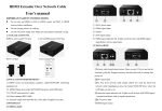
HDMI® Extender over Coaxial Cable with IR*
2.RF to HDMI receiver RX
3 PACKAGE CONTENTS
OR
( ==
H DMI to RF send er TX*lpcs
(==
User Manual
RF to HDMJ receiver RX*lpcs
5. Make sure to have proper ventilation.
(;)
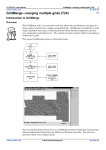
This HDMI over RF extender applies RF conversion technology to
convert HDMisignal to HD digital TV signal and transmits by coaxial
cable up to 700meters. It has the advantage of great image quality and
I
I
©
©
realize one to many and many to many video matrix connection.
Remote control
DC5V1A*2pcs
User's manual*lpcs
CS-HDM3BRX1 ONLY
4 INSTAUATION REQUIREMENTS
5) High quality image, long distance transmission and strong
anti-interference ability.
6) Supports IR control channel switching.*
* CS-HDM3BRX1
(!) RF RX: RF signal receive interface
0 LINK: signal connection led
® DC5V: DC 5V power input
indicator
0 HDMI OUTPUT: HDMI output
splitter function.
'--'="='-='
..• ,-�-�
TI<
�
CATY,pll...,
3.RG5(75-5) or upper level coaxial cables.
C!l Channel setting button
0 Channel display screen
5 PANEL DESCRIPTION
TV
to get image output.
2. Refer to appendix 1 for channel-frequency mapping table; Refer to
appendix 2 for the coaxial cables signal loss for different channel signal.
3. When using CATV splitter forl to many and many to many connection,
it is suggested to use low consumption, high isolation and shielding
-Q
-f �
-0
�
�-
I
(;)
I
0
There are 100 (0-99) channels controlled by 2 buttons. Button left can
,x
5-lOOOMhz bi-directional communication splitter to build video matrix.
Q
TV
7 FAQ
6.3 Many to many connection : Connect two CATV lsplitters to build
video matrix.
2) IfLINK led is not on, check if TX and RX channel setting is the same.
3) If coaxiallcable is too long, please refer to Appendix 1 to adjust
digit and single digit makes 99 channels totally. TX and RX can build
channel setting.
connection only when they are set to same channel parameters and
I
CD
(!) RF TX: RF signal send interface
0 RESET: Press to reset
® DCSV: DC SV power input
I
0
I
0
I
©
0 IR IN: IR receiver extension
cable interface
© HDMI INPUT: HDMI signal input
RX HDMI port outputs the corresponding A/V content.
4. IR remote control
·our
Q.Image is not normal after setting channel (splash screen,
disturbance, mosaic etc)?
as the signal
This IR remote control is just used to set channel.
Note: for above ·CATVsplitterl" , it needs to take
control to IR receiver and press number 9, 9 and enter.
For ·cATV splitter 2· , just follow the marks on the panel description.
For example, set channel to be 99, just aim the IR remote
Q. It shows 'NO SIGNAL" on screen?
A : 1) Make sure to set TV source signal to the correct channel.
select single digit and button right fortens digit. Combination of tens
1) Full compatible with HDCP.
4) Support CATV splitter and amplifier connection.
RX
NOTE: If less than 100' direct point to point, an attenuator or splitter is suggested.
2.Display device with HOM! port.
Features
3) Support up to 100 channels.
TX
® JR IN: IR receiver extension cable interface
3. Channel parameters settings
l.HDMI source device
1. HDMI to TX
2) Transmit up to 700meters with RG6(75-5) at 1080P@60Hz.
DVD
CJ]
than 100meters, it needs to connect a 20dBm(at lleast) signal attenuator
6.2 One-to-many conection : Connect one CATV splitter to realize
strong antiinterference ability and can connect with CATV splitter to
* CS-HDM3BRX1
I I
0 0
to avoid cables damage.
't' Introduction
1. Cable length is suggested to be 300-700meters. If cable is shorter
�····I-+�-+�-+
I
6. Shut off power and make sure environment is safe bef ore installation.
8. Use DCSV only. Make sure the specification matched if using 3rd party
DC adapters.
6.4 Other notes
6.1 One-to-one connection
7. Do not plug-in/out the network cables and IR cables when it is in using
CS-HDM3BTX1
CS-HDM3BRX1
6 Connection
input and ·IN" as signal output.
A : Make sure coaxial cable connection is stable. Try other channel or reset RX.
Q: There is video image output but no sound?
A : Reset TX or re-up TX electricity.
Spec ification
Items
HDMlsignal
Full compatible with HDCP
HDM! OOC signal 5Vp-p(TTL)
HDMI inpuVout
put resolution
480i@60Hz.. 480p@60Hz. 576i@50Hz, 576p@50Hz..
720p@50/60Hz.. 1080i@S0/60Hz.. 1080p@50/60Hz
HDM!�raphics
resolution
video encoding
1280x720@60Hz, 1920x1080@60Hz
H.264
Audio encoding
MPEG2
Coaxial cable
RG6/RG7/RG11
frequency point
100-lOOOM Hz
Effective bit rats
Max:31.6Mbits
insertion loss
<2dBm
RFlXoutput
consumption
+OdBm
RFRX sensitivity
Please refer to Appendix 1
RF interface
imperial system (750 Type F)
Transmi59Clll delay 500ms
Power supply
DC5V/1A
Pcwero:JnlUrTlJlior, TX<3.5W
Enclosure material Metal
RX<3W
Product cinension 130{W)x80(DJx22(HJ*2pcs
Weight
Color
-
Appendix 1:Channel, frequency, c•ble distance mapping table
8 SPECIFICATION
TX:167g RX:169g
Black.
a....i
(0-99)
0
1
2
3
4
5
6
7
8
9
10
11
12
13
14
15
16
17
18
19
20
21
22
23
24
25
26
Frequency bl,nd
C•nter
frequency
177.SM Hz
default
user defined
240
149.5
Special (VHF low band)
Special (VHF low band)
156.5
163.5
Special (VHF low band)
VHFIII
177.5
VHFIII
184.5
VHFIII
191.5
VHF ill
198.5
VHF ill
205.5
VHFIII
212.5
VHFIII
219.5
VHFIII
226.5
Special (UHF hyper band)
410
418
Special (UHF hyper band)
426
Special (UHF hyper band)
Special (UHF hyper band)
434
Special (UHF hyper band)
442
450
Special (UHF hyper band)
458
Special (UHF hyper band)
Special (UHF hyper band)
466
UHF IV
474
482
UHFIV
UHF V
I
490
UHF IV
498
UHFIV
506
UHF IV
514
Blind
width
7
8
7
7
7
7
7
7
7
7
7
7
7
RX
:.(15-5]
M•....,an
-"lv!IJ 111.....
-80
-79
·80
-80
-80
-BO
-80
·79
-75
-75
.79
·79
·80
-79
-79
-79
-79
-79
-79
-79
-79
-79
-79
-78
-76
-71
-76
700
600
700
700
700
700
700
700
700
700
700
700
700
450
450
450
450
450
450
450
450
450
450
450
450
450
400
27
28
29
30
31
32
33
34
35
36
37
38
39
40
41
42
43
44
45
46
47
48
49
so
51
52
53
54
55
56
57
UHF IV
UHF IV
UHFIV
UHF IV
UHFIV
UHF IV
UHFI V
UHFIV
UHF IV
UHFIV
UHF IV
UHFV
UHFV
UHFV
UHFV
UHFV
UHFV
UHFV
UHFV
UHFV
UHFV
UHFV
UHFV
UHFV
UHFV
UHFV
UHFV
UHFV
UHFV
UHFV
UHFV
522
530
538
546
554
562
570
578
586
594
602
610
618
626
634
642
650
658
666
674
682
690
698
706
714
722
730
738
746
754
762
B
B
8
B
8
B
B
8
B
8
8
-77
-74
-77
-78
-76
-78
·78
-78
-75
-64
-76
·78
-78
-78
-78
-75
·76
-77
-77
-78
-77
·77
-78
-77
-77
-77
-76
-70
-64
-77
-78
400
400
400
400
400
400
400
400
400
400
400
350
350
350
350
350
350
350
350
350
350
350
350
350
350
350
350
350
350
350
350
SB
59
60
61
62
63
64
65
51
52
53
54
55
56
57
58
59
60
61
62
63
64
65
66
67
68
69
70
71
72
73
UHFV
UHFV
UHFV
UHFV
UHFV
UHFV
UHFV
UHFV
UHFV
UHFV
UHFV
UHFV
UHFV
UHFV
UHFV
UHFV
UHFV
UHFV
UHFV
UHFV
UHFV
UHFV
UHFV
UHFV
UHFV
UHFV
UHFV
UHFV
UHFV
UHFV
UHFV
770
778
786
794
802
810
818
826
714
722
730
738
746
754
762
770
778
786
794
802
810
818
826
834
842
850
858
866
874
882
890
B
8
8
8
8
8
8
8
8
8
8
8
8
8
8
8
8
8
8
8
8
8
8
8
8
8
8
8
8
8
8
-78
-78
-78
-78
-78
-79
-79
-77
-77
-77
-76
-70
-64
-77
-78
-78
·78
-78
-78
-78
-79
.79
-77
-77
-76
-77
·77
.77
.77
.77
·77
350
350
350
350
350
300
300
300
350
350
350
350
350
350
350
350
350
350
350
350
300
300
300
300
300
300
300
300
300
300
300
74
75
76
77
78
79
80
Bl
82
83
84
85
86
87
88
89
90
91
92
93
94
95
96
97
98
99
UHFV
UHFV
UHFV
UHFV
UHFV
UHFV
UHFV
user defined
user defined
user defined
user defined
user defined
user defined
user defined
user defined
user defined
user defined
user defined
user defined
user defined
user defined
user defined
user defined
user defined
user defined
UHFIV
898
906
915
924
930
938
946
240
250
260
270
280
290
330
340
350
360
370
380
390
400
410
420
430
440
474
8
8
8
8
8
8
8
8
8
8
8
8
8
8
8
8
8
8
8
8
8
8
8
8
8
8
-74
-74
-74
-74
-70
-70
·10
.79
.7 9
.79
.79
.79
.79
.79
.79
.79
.79
.79
.79
.79
·79
.79
.79
.79
-79
-79
300
300
300
300
300
300
300
600
600
600
600
600
600
550
550
550
550
550
550
550
500
450
450
450
450
450
Note:
Above cable length value is offered based on RG6 (75-5} cable transmission.
Professional ones can calculate the transmission length for different material
cables by referring tc appendix 1 and 2.
For example, from appendix 1, it shows channel 5 receive sensitivity is -80dBm.
From appendix 2, it shows 700 meters RG6 cable signal loss value is -61.91
dBm at 211M hz. This value is less than -80dBm and it is within the required
range.
To achieve stable signal transmission, it needs to consider the signal loss
caused by cables and connectors quality and leave more dBm.
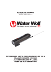
Appendix 2: coaxlal cable slgnal loss table
website: http://www.net-comber.com/cabla-loas. html
Enter cable length: 100, 250,
or 555.55, in feet or meters .
I
I
700
CALC
I Clear
Cable Loss in decibels (dB)
FEET (ft)
Frequucy
RG59/U RG6/U RG7/U RGll/U
2.25
5.39
3.99
3.92
13.16 10.5
8.54
6.65
25.13 20.09 16.03 12.67
MHz
5
55
211
RG59/U
17.68
43.18
82.45
27.23 21.84 17.43 13.86
250
89.34 71.65 57.19
METERS ( Ml
RG6/ U
13.09
34.45
65.91
RG7/U RGll/U
12.86 8.27
28.02 21.82
52.59 41.57
45.47
Dlscl,lmer
• The product name and brand name may be registered trademark of
related manufacturer s.TM and ill) may be o mitted on the user manual.
The pictures on the user manual are just for reference, and there may
be some slight difference with the real products.
We reserve the rights to make changes without further notice to a product
or system described herein to improve reliability, function or design,
1-866-839-9187 - www.MetraHomeTheater.com