1
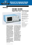
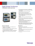
Digital Storage Oscilloscopes
TDS694C • TDS684C
Features & Benefits
3 GHz and 1 GHz Bandwidths
to Work with the Fastest
Signals in Today’s Digital
Designs
10 GS/s and 5 GS/s
Sample Rates on all
Channels Simultaneously
for Full Bandwidth
Single-shot Capture
Waveform Math and
Advanced Waveform DSP
Waveform Pass/Fail
Template Testing
Color Display
RS-232, Centronics and GPIB
Interfaces Included Standard
Record Length to 120,000
Points/Channel*1
TDS694C.
Whether you are working on next generation
microprocessor designs, high-speed data
communications equipment or in high-energy
physics research, the TDS694C captures
your fastest signals with the best fidelity and
resolution available. Its 3 GHz bandwidth
preserves your waveform’s fast rising edges
and accurately shows signal details. With
10 GS/s digitizing rate simultaneously on all
four channels and a high-stability timebase,
the TDS694C makes your critical timing
measurements with the highest resolution
and accuracy – even channel-to-channel
measurements made in a single acquisition.
The TDS600C oscilloscopes incorporate all
the advanced trigger features you expect in
a high performance oscilloscope: triggering
on Glitches, Slew Rate violations, Setup-andhold Time violations, Timeouts, Logic Patterns
and States on four channels. For applications
where sophisticated multi-channel debugging
is required, the TDS694C can be configured
for cross triggering with a Tektronix TLA700
Logic Analyzer.
The TDS600C oscilloscopes give you the total
solution to your digital design characterization
and debugging needs. Now you have the tool
you need to verify design margins, characterize setup-and-hold times and measure clockto-data skew on the fastest digital designs.
The TDS694C’s companion probe, the P6249,
offers small size to reliably contact your highdensity boards with their fine-pitch, hard to
reach components. The P6249 has short
ground connection to give the maximum
system bandwidth and preserve the details
of your signals.
The TDS600C offers 29 automatic measurements, with measurement statistics, to make
your design verification and characterization
job much faster and easier. Available Javabased application packages for jitter analysis,
disk drive measurements and processor
specification measurements provide customized measurements and analysis capability.
The TDS600C gives you the performance and
features you need to get your job done faster
and more thoroughly.
Timebase Accuracy to
10 ppm, Time Interval
Measurement Accuracy to
±15 ps (TDS694C)
Trigger Jitter 8 psRMS (Typical)
1% Vertical Accuracy
(TDS694C)
100 ps Peak Detect
(TDS694C Only)
*1 TDS694C with long record length option (1 M) only.
15,000 points/channel maximum on TDS684C.
Applications
Validation and
Characterization of High
Speed Digital Designs
– Verify Simulation
Performance with Real
Measurements
– Ensure that Desired Design
Margins Exist
– Jitter Measurements on
High-speed Data, Phaselocked Loops and Spreadspectrum Clock Circuits
– Capture Glitches, Cross-talk,
Setup/Hold Violations
Telecommunications/Data
Communications Design
– Characterize Rise Times,
Overshoot, Channel-tochannel Timing
– Verify and Test High-speed
Serial Data Streams
High-energy Physics
– Transient Event Capture
1
Digital Storage Oscilloscopes • www.tektronix.com/scopes
Digital Storage Oscilloscopes
TDS694C • TDS684C
Characteristics
Time Base System
Time Bases – Main and delayed.
Time/div Range – 200 ps/div to 10 s/div.
Except TDS694C: 100 ps/div to 10 s/div.
Input Coupling – AC, DC or GND. Except TDS694C:
DC or GND.
AC Coupled Low Frequency Limit (except
TDS694C) – <10 Hz when AC, 1 MΩ coupled.
<200 kHz when AC, 50 Ω coupled.
Channel Isolation – >100:1 at 100 MHz and
>30:1 at BW for any two channels having
equal V/div settings.
Time Base Accuracy – ±100 ppm. Except
TDS694C: ±10 ppm.
Time Interval Measurement Accuracy –
TDS684C: ±[(0.2/sample rate) + (100 ppm x
|reading|)] single shot. (≈ 50 ps @ 5 GS/s).
TDS694C: ±[(0.15/sample rate) + (10 ppm x
|reading|)] single shot. (≈ 15 ps @ 10 GS/s).
Acquisition Modes
Record Length per Channel – 500 to 15,000 pts.
Except TDS694C: 500 to 30,000 pts.
(optional: 120,000 pts.).
Sample – Sample data only.
Trigger Jitter – 8 psRMS (typical).
Pre-trigger Position – 0% to 100% of record.
Channel-to-channel Deskew Range – ±25 ns.
Vertical System
Vertical Resolution – 8-Bit (>11-Bit with averaging).
Vertical Sensitivity – 1 mV/div to 10 V/div.
Except TDS694C: 10 mV/div to 1 V/div.
Floppy Disk Drive – Store reference waveforms,
setups and image files on 3.5 in. 1.44 MB or 720 K
Microsoft DOS-format floppy disk.
Maximum Input Voltage – 300 V CAT II; ±400 V
peak. Derate at 20 dB/decade above 1 MHz.
Except TDS694C: 5 VRMS.
DC Gain Accuracy – ±1.5%.
Except TDS694C: ±1.0%.
Position Range – ±5 divs.
Offset –
±1 V from 1 to 99.5 mV/div, ±10 V from 100 mV to
995 mV/div, ±100 V from 1 V to 10 V/div.
Except TDS694C: ±0.5 V from 10 to 50 mV/div,
±0.25 V from 50.5 to 100 mV/div, ±5 V from 101 mV
to 500 mV/div, ±2.5 V from 505 mV to 1 V/div.
Bandwidth Selections – 20 MHz, 250 MHz and full.
Except TDS694C: Full only.
Input Impedance Selections – 1 MΩ in parallel with
10 pF, or 50 Ω (AC and DC coupling).
Except TDS694C: 50 Ω (DC coupled).
2
Digital Storage Oscilloscopes • www.tektronix.com/scopes
Peak Detect – High frequency and random glitch
capture. Captures glitches of 1 ns using acquisition
hardware at all real-time sampling rates. TDS694C
captures glitches of 100 ps.
Envelope – Max/min values acquired over one
or more acquisitions.
Average – Waveform data from 2 to 10,000
waveforms (selectable) is averaged.
Single Sequence – Use RUN/STOP button to capture
a single triggered acquisition at a time, which may be
automatically saved to NVRAM with AutoSave.
Triggering System
Trigger Types
EDGE (main and delayed) –
Conventional level-driven trigger. Positive or negative
slope on any channel or rear panel auxiliary input.
Coupling selections: DC, AC, noise reject, HF reject,
LF reject.
LOGIC (main) –
PATTERN: Specifies a logical combination (AND, OR,
NAND, NOR) of the four input channels (high, low,
don’t care). Trigger when pattern stays true or false
for a specified time.
STATE: Any logical pattern of channels 1, 2 and 3 plus
a clock edge on channel 4. Triggerable on rising or
falling clock edge.
SETUP/HOLD: Trigger on violations of both setup time
and hold time between clock and data which are on
two input channels.
PULSE (main) –
GLITCH: Trigger on or reject glitches of positive,
negative or either polarity. Minimum glitch width
is 1.0 ns with 200 ps resolution.
RUNT: Trigger on a pulse that crosses one threshold
but fails to cross a second threshold before crossing
the first again.
WIDTH: Trigger on width of positive or negative
pulse either within or out of selectable time limits
(1 ns to 1 s).
SLEW RATE: Trigger on pulse edge rates that are
either faster or slower than a set rate. Edges can
be rising, falling or either.
TIMEOUT: Trigger on an event which remains high,
low or either, for a specified time period, selectable
from 1 ns to 1 s, with 200 ps resolution.
TLA Cross Trigger (TDS694C only) – Utilize a
TLA700 logic analyzer to detect a multi-channel
event, then trigger the TDS694C. The trigger points
on the TLA and TDS will be aligned in time.
VIDEO (optional; not available in TDS694C) –
Trigger on a particular line of individual, odd/even or
all fields. Trigger on a specific pixel of a line by using
the video trigger with delay by events. Choose positive
or negative horizontal sync polarity.
525/NTSC: Choose monochrome or color (studioquality NTSC) sync formats. 625/PAL: Choose color
or monochrome (studio-quality PAL) sync formats.
HDTV: Choose from 1125/60, 1050/60, 1250/50
and 787.5/60 HDTV formats.
Trigger Bandwidth (edge type) –
3 GHz (TDS694C).
1 GHz (TDS684C).
Main Trigger Modes – Auto, normal, single.
Delayed Trigger – Delay by time, events, or events
and time.
Delay by Time Range – 16 ns to 250 s.
Delay by Events Range – 2 to 9,999,999 events.
External Trigger Input – Input impedance: ≥1.5 kΩ;
max. input voltage: ±20 V (DC + peak AC).
Digital Storage Oscilloscopes
TDS694C • TDS684C
Display Characteristics
Waveform Style – Dots, vectors, variable persistence
from 32 ms to 10 s, infinite persistence and intensified
samples.
Color – Standard palettes and user-definable color for
waveforms, text, graticules and cursors. Measurement
text and cursor colors matched to waveform.
Waveform collision areas highlighted with different
color. Statistical waveform distribution shown with
color grading through variable persistence.
Color Grading – With variable persistence selected,
historical timing information is represented by
temporal or spectral color scheme.
Graticules – Full, grid, cross-hair, frame and NTSC
and PAL (with video trigger option).
Format – YT and XY.
Resolution – 640 horizontal by 480 vertical displayed
pixels (VGA).
Color CRT Monitor – 7 in. diagonal NuColor™ liquid
crystal full-color shutter, 256 levels.
Measurement System
Automatic Waveform Measurements –
Period, frequency, +width, –width, rise time, fall time,
+duty cycle, –duty cycle, delay, phase, burst width,
high, low, max, min, peak to peak, amplitude, +overshoot, –overshoot, mean, cycle mean, RMS, cycle RMS,
area, cycle area, extinction ratio (ratio, dB, %) and
mean optical power. Continuous update of up to four
measurements on any combination of waveforms.
Measurement Statistics – Display minimum and
maximum or mean and standard deviation on any
displayed single-waveform measurements.
Thresholds – Settable in percentage or voltage.
Gating – Any region of the waveform may be isolated
for measurement using vertical bars.
Snapshot – Performs all measurements on any one
waveform showing results from one instant in time.
Cursor Measurements – Absolute, delta: Volts, time,
frequency, and NTSC IRE and line number (with video
trigger option).
Cursor Types – Horizontal bars (volts), vertical bars
(time); operated independently or in tracking mode.
Histogram Measurements – Mean, median, standard deviation, hits, waveform count, peak hits, peakto-peak, % mean ±1, 2 and 3 standard deviations.
Waveform Processing
Waveform Functions – Interpolation (sin(x)/x or linear),
average, envelope, auto setup.
Advanced Waveform Functions – FFT, integration,
differentiation, waveform (math or acquired) limit
testing.
Arithmetic Operators – Add, subtract, multiply,
divide, invert.
Autoset – Single-button, automatic setup on
selected input signal for vertical, horizontal and
trigger systems.
Waveform Limit Testing – Compares incoming or
math waveform to a reference waveform’s upper and
lower limits.
Waveform Histograms – Both vertical and horizontal
histograms, with periodically updated measurements,
allow statistical distributions to be analyzed over any
region of the signal.
Environmental and Safety
Temperature –
Operating: +4°C to +45°C (floppy not used),
+10°C to +45°C (floppy in use).
Nonoperating: –22°C to +60°C.
TDS694C: Operating: +5°C to +40°C (floppy not
used), +10°C to +40°C (floppy in use).
Nonoperating: –22°C to +60°C.
Humidity – Operating: 20% to 80% RH at
or below +32°C.
Altitude – Operating: 15,000 ft. (hard disk not used),
10,000 ft. (hard disk in use). Nonoperating: 40,000 ft.
Electromagnetic Compatibility – 89/336/EEC.
Safety – UL 3111-1, CSA1010.1, EN61010-1,
IEC61010-1.
Physical Characteristics
Dimensions
Height with feet
Height without feet
Width with handle
Depth with front
cover installed
Weight
Net approximately
Shipping weight
approximately
mm
193
178
445
434
in.
7.6
7
17.5
17.1
kg
14.1
24.0
lbs.
31
53
Power Requirements
Line Voltage Range – 100 to 240 VRMS.
Line Frequency – 45 to 440 Hz.
Power Consumption – 300 W max. (TDS654C/684C).
450 W max. (TDS694C).
Digital Storage Oscilloscopes • www.tektronix.com/scopes 3
Digital Storage Oscilloscopes
TDS694C • TDS684C
Ordering Information
TDS694C
Four-channel Color 3 GHz, 10 GS/s Per Channel,
Digital Storage Oscilloscope.
Includes: User manual (071-0473-00), quick
reference guide (071-2313-00), programmer’s
manual in MS Help format on floppy disk
(063-3060-00), technical reference (performance
verification) manual (071-0496-00), probe deskew
fixture (679-4809-00), footswitch and adapter
(260-1189-02 and 013-0312-00), front cover
(200-3696-00), North American power cord
(161-0230-01), accessory pouch (016-1268-00).
TDS684C
Four-channel Color 1 GHz, 5 GS/s Per Channel
Digital Storage Oscilloscope.
Includes: User manual (070-0130-00), user
supplement (071-0273-00), quick reference
guide (020-2235-00), programmer’s manual in
MS Help format on floppy disk (063-3120-00),
technical reference manual (071-0272-00).
Options
Opt. 05 – Video Trigger, NTSC, PAL, HDTV,
FlexFormat™ (Except TDS694C).
Opt. 1K – Model K420 Instrument Cart.
Opt. 1M – 120 K Record Length (TDS694C only).
Opt. 1R – Rackmount Kit.
Opt. 31 – Add 1 ea. P6339A Buffered Passive Probe
(TDS694C only).
Opt. 33 – Add 1 ea. P6158 Low Capacitance Probe.
Opt. 34 – Add 1 ea. P6247 Differential Probe
(Except TDS694C).
Opt. 36 – Add 1 ea. P6139A Passive Probe
(Except TDS694C).
Opt. 37 – Add 1 ea. P6245 Active Probe.
Opt. 38 – Add 1 ea. P6249 4 GHz Active Probe
(TDS694C only).
Opt. 39 – Add 1 ea. P6248 1.7 GHz Differential
Probe (TDS694C only).
Opt. HD – Internal hard disk drive.
International Power Plugs
Contact Tektronix:
Opt. A1 – Universal Euro 220 V, 50 Hz.
Opt. A2 – UK 240 V, 50 Hz.
Opt. A3 – Australian 240 V, 50 Hz.
Opt. A4 – North American; product set to operate
at 60 Hz, 15A.
Opt. A5 – Switzerland 220 V, 50 Hz.
Opt. AC – China 240 V, 50 Hz.*1
ASEAN Countries & Pakistan (65) 6356 3900
Australia & New Zealand (65) 6356 3900
Austria +43 2236 8092 262
Belgium +32 (2) 715 89 70
Brazil & South America 55 (11) 3741-8360
Canada 1 (800) 661-5625
Measurement Service Options
Opt. C3 – Three years of Calibration Services.
Opt. D1 – Calibration data report.
Opt. D3 – Test data (requires Opt. C3).
Central Europe & Greece +43 2236 8092 301
Denmark +45 44 850 700
Finland +358 (9) 4783 400
Software
France & North Africa +33 (0) 1 69 86 80 34
TDS Java Applications
Germany +49 (221) 94 77 400
USB and TDSUSBF – USB2.0 compliance test
package (includes software and test fixture).
TDSJIT1V2 – Jitter and timing analysis application.
TDSDDM1 – Hard disk drive measurement
application.
TDSPRT1 – Enhanced waveform printing application.
TDSRBS1 – Rambus timing measurements – ME.
WSTRO – WaveStar™ software for oscilloscopes,
Windows 95/NT application for waveform capture,
analysis, documentation and control from your PC.
WSTROU – Upgrade from WSTR31 to WSTRO.
LVWCVI95 – LabWindows/CVI for Windows 95.
Hong Kong (852) 2585-6688
India (91) 80-2275577
Italy +39 (02) 25086 1
Japan (Sony/Tektronix Corporation) 81 (3) 3448-3111
Mexico, Central America & Caribbean 52 (55) 56666-333
The Netherlands +31 (0) 23 569 5555
Norway +47 22 07 07 00
People’s Republic of China 86 (10) 6235 1230
Recommended Accessories
Poland +48 (0) 22 521 53 40
P6249 – 4 GHz Active Probe.
P6248 – 1.7 GHz Differential Probe.
P6330 – 3.5 GHz Differential Probe.
SureFoot® – Surface mount device interconnects.
Republic of Korea 82 (2) 528-5299
Russia, CIS & The Baltics +358 (9) 4783 400
South Africa +27 11 254 8360
Spain +34 (91) 372 6055
*1 Not in TDS694C.
Sweden +46 8 477 6503/4
Taiwan 886 (2) 2722-9622
United Kingdom & Eire +44 (0) 1344 392400
USA 1 (800) 426-2200
For other areas contact Tektronix, Inc. at: 1 (503) 627-7111
Updated 8 February 2002
For the most up-to-date product information
visit our web site at www.tektronix.com
Copyright © 2002, Tektronix, Inc. All rights reserved. Tektronix products are
covered by U.S. and foreign patents, issued and pending. Information in this publication supersedes that in all previously published material. Specification and price
change privileges reserved. TEKTRONIX and TEK are registered trademarks of
Tektronix, Inc. All other trade names referenced are the service marks, trademarks
or registered trademarks of their respective companies.
02/02
4
Digital Storage Oscilloscopes • www.tektronix.com/scopes
HB/PG
55W-10066-9