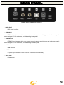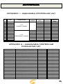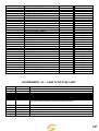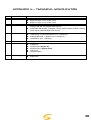
1
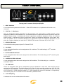
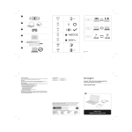
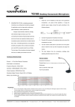
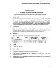
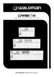
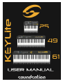
Dear customer,
first of all thanks for purchasing a SOUNDSATION® product. Our mission is to satisfy all the
possible needs of musical instrument and professional audio users offering a wide range of
products using the latest technologies for a reasonable price.
We hope you will be satisfied with this item and, if you want to collaborate, we are looking
for a feedback from you about the operation of the product and for possible
improvements to introduce in the next future. Go to our website
www.soundsationmusic.com and send an e-mail with your opinion, this will help us to build
instruments ever closer to customer’s real requirements.
One last thing: read this manual before using the instrument, an incorrect operation can
cause damages to you and to the unit. Take care!
The SOUNDSATION Team
2
TABLE OF CONTENTS
UNBOXING……………………………………………………………………………………………………………………………………..…4
ACCESSORIES…………………………………………………………………………………………………………………………………....4
GENERAL WARNINGS………………………………………………………………………………………………………………….…..…5
FEATURES………………………………………………………………………………………………………………………………………....6
TOP PANEL……………………………………………………………………………………………………………………………………..…7
REAR PANEL…………………………………………………………………………………………………………………………………..….8
ADVANCE FUNCTION MODE………………………………………………………………………………….……………..………….10
ASSIGN...10
VELOCITY CURVE10
PEDAL CURVE..10
TEMPO.11
PROGRAM....11
MIDI CHANNEL .......... .........11
TRANSPOSE ..................................................................................... ..11
OCTAVE .......................................................................................................................................11
DUAL .............................................................................................................................................12
SPLIT.............................................................................................................................................12
SPLIT POINT ...............................................................................................................................12
MTC ...............................................................................................................................................12
ACTIVE SENSING ......................................................................................................................12
LOCK .............................................................................................................................................12
MUTE ............................................................................................................................................13
SNAP SHOT .................................................................................................................................13
UPLOAD/DOWNLOAD ...............................................................................................................13
PEDAL POLARITY ......................................................................................................................13
ALL SOUND OFF ...........................................................................................................................13
ALL NOTE OFF ...........................................................................................................................13
CTRL RESET ...............................................................................................................................14
GM/GS/XG ON ............................................................................................................................14
GM ON ..........................................................................................................................................14
GM2 ON ........................................................................................................................................14
GS ON .......................................................................................................................................... 14
XG ON ...........................................................................................................................................14
PRESET14
0-9 / CLEAN14
APPENDIX…………….……………………………………………………………………………………………………………………………….15
APPENDIX 1 - ASSIGNABLE CONTROLLER LIST....15
APPENDIX 2 - ASSIGNABLE CONTROLLER PARAMETER LIST.....15-16-17
APPENDIX 3 – LED STATUS LIST...17
APPENDIX 4 –TECHNICAL SPECIFICATION....18
WARRANTY & SERVICE……………………………………………………………………………………………………..…………….19
LEGAL INFORMATION & CONTACTS…………………………..…………..………………………………………..…………….20
3
UNBOXING
When you’ll open the box you will find the following items:
- Keylite Master Keyboard (25,49 or 61 Keys)
- USB Cable
- User Manual CD
The packaging bag is not a toy! Keep out of reach of children.
Keep in a safe place the original packaging material for future use.
The unit is projected to be powered trough USB, so the external device you will plug to the
keyboard will supply the right voltage to let the keyboard works. If you want to use the
keyboard to pilot an external device via traditional MIDI OUT connector you need to supply
the voltage required (9VDC-Center Positive) with an external PSU. Ask your SOUNDSATION
Center for a PSU-20 to ensure best performance. An incorrect PSU can damage the
instrument and the warranty immediately dies.
ACCESSORIES
KEYLITE keyboards can be used with several accessories like Pedals, Switches or Sustain
Pedals as well as the aforementioned PSU-20 Power Supply.
It’s really suggested to use SOUNDSATION Accessories to prevent possible incompatibility
with other product from other manufacturer.
Ask your SOUNDSATION dealer for any accessories you could need to ensure best
performance of the product.
4
GENERAL WARNINGS
To prevent possible damages read the following list of actions:
- Do not place the instrument in wet or dirty environments.
- Do not remove the protective coverings.
-Do not cover any of the instrument’s ventilation holes.
- Air must circulate freely around the instrument.
-
- Do not set the instrument on a surface with excessive vibration.
- Do not expose the instrument to electro-magnetic interference.
- Do not expose the instrument to heat, cold, wet or dust.
- Do not leave the instrument in direct sunlight.
- Do not expose the instrument to electrostatic forces.
- Do not place items with flames, such as candles or lighters, on the
instrument.
- Do not place the instrument on anything containing water or other
fluids.
If any foreign objects enter the instrument, please contact your dealer or an authorized
SOUNDSATION center.
The serial number, electrical features and international standards are printed on a label
located in the bottom of the instrument.
In case of problems remember to give the serial number to the responsible of the technical
assistance.
5
GETTING STARTED
The Keylite series is designed to be a powerful resource both for studio and live
performances. The friendly user interface is one of the best features of these products and
this allow you to configure your sound device in a fast and easy way.
Keylite Keyboards are designed to work with any PC or MAC hardware and with any DAW.
You don’t need to install a specific driver because this is a Plug&Play device.
ALL
DAW
COMPATIBILITY
You have just to plug the USB cable on the keyboard and then plug the other side on your
computer. Open the software menu in which is possible to define the MIDI Device to use
and select “USB Midi Controller” from the available devices.
If you use the Midi Out port be sure that the module you are using is able to receive the
Midi messages in the same Channel in which the Keylite is working (Default Ch is 1).
You can plug 2 switch or continuous pedal on the Keylite. It’s really suggested to use
genuine SOUNDSATION pedals. Ask your dealer for a compatible SOUNDSATION pedal.
Before connecting any other pedal please read carefully the specific section of this manual
where you can find all the instruction to adjust the resistance read range of pedals.
6
FEATURES
25/49/61 Dynamic keys
1 x Assignable pedal interface (PEDAL B), compatible with switch pedal and continuous pedal. It
can be assigned as 152 controllers. (K25).
2 x Assignable pedal interfaces (PEDAL A,PEDAL B), compatible with switch pedal and
continuous pedal. It can be assigned as 152 controllers. (K49/61)
1 x Assignable slider .
Pitch Bend and Modulation Wheel (WHEEL P and WHEEL M), which can be assigned as 148
controllers.
2 x Assignable data buttons (DATA +/-), which can be assigned as 160 controllers.
1 x Edit button (EDIT), switching from play to edit status.
1 x Dial function group switching from C1-C4 to C5-C8 pots.
4 x Assignable Pots, assignable as 160 controllers with independent channel.
5 x Keyboard Velocity Curve
PC upload and download to fastly Import/export your DAW settings
Multi-functional keyboard, which can provide functions such as voice adjustment, dual, touch
sensitivity adjustment, split, tempo, mute, snap shot, etc.
1 x MIDI OUT.
USB interface, adaptable to USB 1.1. Power supply by USB and DC 9V.
Compatible with Win XP/Vista and Mac OSX, drive free and hot plug supporting.
Compatibility with major audio and sequencer software, such as Pro-Tools Cubase,Cakewalk Etc.
7
TOP PANEL
The top panel is common for Keylite 25/49/61.
1 - EDIT Button
It is to open/close keyboard multi-function. . When LED indicator is on, keyboard multi-function is on,
viceversa.
2 - DATA +/- Buttons
They are assignable buttons assignable as 160 controllers. The initial setting is 154th controller: octave
adjustment. When the LED indicator is on, it indicates that there’s upper/lower octave adjustment; when the
indicator flickers slowly, it indicates that there’s upper/lower transpose adjustment; when the indicator
flickers quickly, it indicates that there’s upper/lower octave and transpose adjustment at the same time;
when the indicator is off, it indicates that there’s no upper/lower octave nor transpose adjustment. If you
press the 2 buttons togheter you send the CC 120&123 (All sound off-All notes off) on Ch1 & Ch2.
3 - GROUP Button
It is to switch function groups of pots C1~C4 and C5~C8.
4 - SLIDER
It is an assignable fader that can be assigned as 148 controllers. The initial setting is 147th controller:
master volume.
5 - PITCH BEND Wheel
It is an assignable wheel that can be assigned as 148 controllers. The initial setting is 146th controller: pitch
bend wheel.
6 - MODULATION Wheel
It is an assignable wheel that can be assigned as 148 controllers. The initial setting is 1st controller:
modulation wheel.
7 - C1~C8 Pots
These are assignable dials with an independent channel distributed to each dial, and each dial can be
assigned as 160 controllers. The initial channel of C1~C4 is 0, initial controller numbers are 152, 153, 156,
157, which controls program, channel, tempo and keyboard velocity curve respectively. The initial channels
of C5~C8 are 0~3, initial controller number is 7, which controls the volume of channels 0~3 respectively.
The function group of C1~C4 and C5~C8 is switched by GROUP button.
8 - LCD Display
It indicates the current number/status information.
8
REAR PANEL
Pedal 2 is not available on Keylite 25
1 - MIDI OUT
MIDI output interface.
2 - PEDAL 1
PEDAL A input interface, which can connect to pedals of both switching type and continuous type. It
can be assigned as 152 controllers; the initial setting is soft pedal.
3 - PEDAL 2
PEDAL B input interface, which can connect to pedals of both switching type and continuous type. It
can be assigned as 152 controllers; the initial setting is sustain pedal.
4 - USB
USB interface
5 - DC 9V
9V power input interface. Center Positive. (PSU-20 is recommended)
6 - OFF/ON
Power Off/On
9
ADVANCED FUNCTION MODE
KEYLITE keyboards are suitable to send the complete range of GENERAL MIDI messages.
Above the first 49 keys (25 keys on K25) there are printed labels that allow you to enter the Advance
Function in EDIT mode. Here following the specification for each function.
ASSIGN
Press EDIT button to enter keyboard Advanced Function mode, the LED of EDIT is on. Press ASSIGN
button to enter controller assignment mode, LCD shows CHO, reminding the user to choose the controller
that needs to be assigned. Move the desired control to select it (For example, if you want to assign
SLIDER, move the SLIDER to select), the LCD shows the controller number of the selected controller, input
the desired assignable parameter value with numeric pad and press ENTER to confirm (for example, if
Slider is selected, input 147 and the Slider is assigned as Master Volume Controller).
* Assignable controllers reference: Appendix 1 - Assignable Controller List
* Assignable controller parameters reference: Appendix 2 - Assignable Controller Parameter List.
PEDAL CURVE
You can adjust the pedal resistance curve to better work with pedals of different specifications from
SOUNDSATION pedals.
Estimate resistance curve value
Value of Pedal CURVE = (128 x pedal resistance value) / (10K + pedal resistance value)
EX. if the pedal resistance value is 10K, the value of Pedal CURVE is:
128*10K/ (10K+10K) = 64
For pedal resistance value, please refer to the technical specifications provided by pedal manufacturer.
The resistance curve estimation does not need to be very accurate, or you could simply adjust it without
calculation, as long as the travel and succession of the pedal satisfy your needs.
The initial value of resistance curve is 64, adaptable to most pedals in the market.
When you use switching type pedal, the recommended resistance curve value is 64.
When DATA +/- is assigned as Pedal 1 CURVE or Pedal 2 CURVE, DATA +/- can be used to adjust
resistance curve values. Press two buttons of DATA +/- at the same time to set the resistance curve value
to initial 64.
When the pots (C1~C4 or C5~C8)are assigned as Pedal 1 CURVE or Pedal 2 CURVE, they can be
used to adjust pedal resistance value.
Press EDIT button to enter keyboard multi-function mode, press Pedal 1 CURVE or Pedal 2 CURVE multifunctional keys to enter pedal resistance curve adjustment mode, input the pedal resistance value with
numeric pad, then press ENTER to confirm.
VELOCITY CURVE
Velocity curve can be adjusted to find the best feeling with the keyboard.
Press EDIT button then Press VEL CURVE and press a number from 0 to 4 (5 different curves).Press
ENTER to confirm.
10
TEMPO
Which adjust the tempo of MIDI Time Code (MTC
MTC).
MTC
When DATA +/- is assigned as TEMPO, it can be used to adjust tempo. Press DATA +/- at the same time
to set the tempo to initial 100.
When the pots (C1~C4 or C5~C8) are assigned as TEMPO they can be used to adjust tempo.
Press EDIT button to enter keyboard multi-function mode, press TEMPO to enter tempo adjustment mode,
then input the tempo value with numeric pad, and press ENTER to confirm. (K49/61).
PROGRAM
Voice adjusting function, adjusting the voice of current channel.
When DATA +/- is assigned as PROGRAM, DATA +/- can be used to adjust program. Press DATA +/- at
the same time to set the program number to initial 0.
When the pots(C1~C4 or C5~C8)are assigned as PROGRAM they can be used to adjust program.
Press EDIT button to enter keyboard multi-function mode, press PROGRAM button to enter program
adjustment mode, then input the program number with numeric pad and press ENTER to confirm.
MIDI CHANNEL
When DATA +/- is assigned as CHANNEL, use DATA +/- to adjust general MIDI channel. Press DATA +/buttons at the same time to set general MIDI channel to initial 0.
When pots C1~C4 or C5~C8 are assigned as CHANNEL they can be used to adjust general MIDI channel.
Press EDIT button to enter keyboard multi-function mode, and then press CHANNEL to enter channel
adjustment mode and then use numeric pad (or C1~C4 or C5~8) to enter general MIDI channel number
and press ENTER to confirm.
TRANSPOSE
This function allows the keyboard to change the pitch up/down by semi-tone.
When DATA +/- is assigned as TRANSPOSE use DATA +/- to adjust transpose. Adjustment range is +/12 semitones. Press DATA +/- buttons at the same time to set transpose to initial 0.
Hold EDIT and use DATA +/- to adjust transpose. Adjustment range is +/- 12 semitones. Hold EDIT and
DATA +/- at the same time to set transpose to initial 0.
When pots C1~C4 or C5~C8 are assigned as TRANSPOSE you can use it to adjust transpose.
Adjustment range is +/- 12 semitones.
OCTAVE
This function allows the keyboard to change the pitch up/down by octave.
When DATA +/- is assigned as OCTAVE, use DATA +/- to adjust octave. Adjustment range is +/- 3
octaves. Press DATA +/- buttons at the same time to set octave to initial 0.
When pots C1~C4 or C5~C8 are assigned as OCTAVE they can be used to adjust octave. Adjustment
range is +/- 3 octaves.
11
DUAL
When DUAL is ON, Keyboard/Wheel/Pedal/Slider sends MIDI info If two channels (default 1-2), with the
voice/channel of both channels adjustable.
Press EDIT button to enter keyboard multi-function mode, and then press DUAL to open/close dual
function.
Dual and keyboard split functions cannot be used simultaneously. Open dual will turn off keyboard split
function.
SPLIT
(49 and 61 version only) .When SPLIT is ON, Wheel/Pedal/ Slider sends MIDI info of two channels, the
keyboard is split to right section and left section by the split point. The voice/channel of both channels is
adjustable.
Press EDIT button to enter keyboard multi-function mode, and then press SPLIT to open /close keyboard
split function.
Dual and keyboard split functions cannot be used simultaneously. Open keyboard split will turn off dual
function.
SPLIT POINT
Default Split Point is the central C (MIDI No. 60). User can choose the Split Point.
Press EDIT button to enter keyboard multi-function mode, and then press SPLIT POINT to select split
point. LED displays CHO to remind users to select the split point, and then press the desired split point note
and then that note will be the new split point.
MTC
Press EDIT button to enter keyboard multi-function mode, and then press MTC to open/close sending MTC
message (F8).
ACTIVE SENSING
(49 and 61 version only) Press EDIT button to enter keyboard multi-function mode, and then press ACTIVE
SENSING to open/close active sensing message (FE).
LOCK
(49 and 61 version only) Press EDIT button to enter keyboard multi-function mode, and then press LOCK
to open/close lock function. No other controllers except keyboard can be operated under Lock mode.
12
MUTE
Press EDIT button to enter keyboard multi-function mode, and then press MUTE to open/close mute
function. No message will be transmitted under Mute mode.
SNAP SHOT
Press EDIT button to enter keyboard multi-function mode and then press SNAP SHOT: all the controls will
be sent in the same time.
UPLOAD/DOWNLOAD
Use USB port to connect with computer can upload or download user parameters: to upload Keylite panel
parameters to computer, or to download the parameters from computer to Keylite keyboards.
The transmitted messages are system exclusive messages in form of F0..F7. According to different
sequencer software, there are different ways to receive/send system message: mainly record/playback
style and system message window style.
PEDAL POLARITY
(49 and 61 version only) System can recognize or change pedal polarity. If you want pedal to transmit
PEDAL ON message while pressing the pedal and PEDAL OFF message while releasing the pedal, you do
not need to do any adjustment. Otherwise, you can press down the pedal while switching on this unit and
release the pedal after the unit is turned on.
Press EDIT button to enter keyboard multi-function mode, and press PEDAL A POLARITY or PEDAL B
POLARITY to adjust pedal polarity.
ALL SOUND OFF
(49 and 61 version only) Press EDIT button to enter keyboard multi-function mode, and then press ALL
SOUND OFF to transmit all sound off MIDI message (Controller #120), in case of abnormal constant sound
from system or external sound module.
ALL NOTE OFF
(49 and 61 version only) Press EDIT button to enter keyboard multi-function mode, and then press ALL
NOTE OFF to transmit all notes off message (Controller #123), in case of abnormal constant sound from
system or external sound module.
13
CTRL RESET
Press EDIT button to enter keyboard multi-function mode, and then press CTRL RESET to transmit all
reset all controllers message (Controller #121).
GM/GS/XG ON
(25 notes version) Press EDIT button to enter keyboard multi-function mode, and then press GM/GS/XG
ON to transmit GM initialization message (F0 7E 7F 09 01 F7), GS initialization message (F0 41 10 42 12 40
00 7F 00 41 F7), and XG initialization message (F0 43 10 4C 00 00 7E 00 F7).
GM ON
(49 and 61 version only) Press EDIT button to enter keyboard multi-function mode, and then press GM ON
to transmit GM initialization message (F0 7E 7F 09 01 F7).
GM 2 ON
(49 and 61 version only) Press EDIT button to enter keyboard multi-function mode, and then press GM2
ON to transmit GM2 initialization message (F0 7E 7F 09 03 F7).
GS ON
(49 and 61 version only) Press EDIT button to enter keyboard multi-function mode, and then press GS ON
to transmit GS initialization message (F0 41 10 42 12 40 00 7F 00 41 F7).
XG ON
(49 and 61 version only) Press EDIT button to enter keyboard multi-function mode, and then press XG ON
to transmit XG initialization message (F0 43 10 4C 00 00 7E 00 F7).
PRESET
(49 and 61 version only) Press EDIT button to enter keyboard multi-function mode and then press
PRESET to return to factory preset.
System starts SNAP SHOT function to transmit preset to sequent device.
0-9 – CLEAN - ENTER
Use numerical to insert specifical values of overwritten parameters. Press CLEAN to erase value in case of
mistakes and press ENTER to confirm every operation you make as written above.
14
APPENDIX
APPENDIX 1 – ASSIGNABLE CONTROLLER LIST
NO.
1
2
3
4
5
6
7
8
9
10
11
12
13
14
ITEM
DATA +/SLIDER
WHEEL P
WHEEL M
PEDAL A
PEDAL B
R1
R2
R3
R4
R5
R6
R7
R8
CHANNEL RANGE
INITIAL
CHANNEL
PARAMTER
RANGE
INITIAL
PARAMETER
INITIAL
PARAMETER
VALUE
0
0~159
0~147
0~147
0~147
0~151
0~151
0~159
0~159
0~159
0~159
0~159
0~159
0~159
0~159
154
147
146
1
64
67
152
153
156
157
7
7
7
7
0
0
64
0
0
0
0
0
100
0
100
100
100
100
0~15
CURRENT CHANNEL
0~15
INDEPENDENT CHANNEL
0
0
0
0
0
1
2
3
APPENDIX 2 – ASSIGNABLE CONTROLLER
PARAMETER LIST
CONTROLLER NO.
0
1
2
3
4
5
6
7
8
9
10
11
12
13
14-31
32
33
34
35
36
DEFINITION
BANK SELECT MSB
MODULATION MSB
BREATH MSB
CONTROLLER
FOOT CONTROLLER MSB
PORTAMENTO TIME MSB
DATA ENTRY MSB
CHANNEL VOLUME MSB
BALANCE MSB
CONTROLLER
PAN MSB
EXPRESSION MSB
EFFECT CONTROL 1 MSB
EFFECT CONTROL 2 MSB
CONTROLLER
BANK SELECT LSB
MODULATION LSB
BREATH LSB
CONTROLLER
FOOT CONTROLLER LSB
INITIAL VALUE
0
0
127
0
127
0
2
100
64
0
64
127
0
0
0
0
0
127
0
127
VALUE RANGE
0-127
0-127
0-127
0-127
0-127
0-127
0-127
0-127
0-127
0-127
0-127
0-127
0-127
0-127
0-127
0-127
0-127
0-127
0-127
0-127
15
CONTROLLER NO.
37
38
39
40
41
42
43
44-63
64
65
66
67
68
69
70
71
72
73
74
75
76
77
78
79
80-83
84
85-90
91
92
93
94
95
96
97
98
99
100
101
102-119
120
121
122
123
124
125
126
127
128
129
130
131
DEFINITION
PORTAMENTO TIME LSB
DATA ENTRY LSB
CHANNEL VOLUME LSB
BALANCE LSB
CONTROLLER
PAN LSB
EXPRESSION LSB
CONTROLLER
SUSTAIN
PORTAMENTO
SOSTENUTO
SOFT PEDAL
LEGATO FOOTSWITCH
HOLD 2
SOUND CONTROLLER
RESONANCE
RELEASE TIME
ATTACK TIME
CUTOFF
DECAY TIME
VIBRATO DEPTH
VIBRATO DEPTH
VIBRATO DEPTH
SOUND CONTROLLER
CONTROLLER
PORTAMENTO CONTROL
CONTROLLER
REVERB
EFFECTS
CHORUS
EFFECTS
EFFECTS
RPN INCREMENT
RPN DECREMENT
NRPN LSB
NRPN MSB
RPN LSB
RPN MSB
CONTROLLER
ALL SOUND OFF
RESET ALL CONTROLLERS
LOCAL CONTROL
ALL NOTES OFF
OMNI OFF
OMNI ON
MONO
POLY
PITCH BEND SENSITIVITY(RPN)
CHANNEL FINE TUNING(RPN)
CHANNEL COARSE TUNING(RPN)
MODULATION DEPTH RANGE(RPN)
INITIAL VALUE
0
0
127
64
0
64
127
0
0
0
0
0
0
0
64
64
64
64
64
64
64
64
64
64
0
0
0
64
0
0
0
0
0
0
0
0
0
0
0
0
0
0
0
0
0
0
0
2
64
64
64
VALUE RANGE
0-127
0-127
0-127
0-127
0-127
0-127
0-127
0-127
0-127
0-127
0-127
0-127
0-127
0-127
0-127
0-127
0-127
0-127
0-127
0-127
0-127
0-127
0-127
0-127
0-127
0-127
0-127
0-127
0-127
0-127
0-127
0-127
0-127
0-127
0-127
0-127
0-127
0-127
0-127
0-127
0-127
0-127
0-127
0-127
0-127
0-127
0-127
0-127
0-127
0-127
0-127
16
CONTROLLER NO.
132
133
134
135
136
137
138
139
140
141
142
143
144
145
146
147
148
149
150
151
152
153
154
155
156
157
158
159
DEFINITION
VIBRATO RATE(NRPN)
VIBRATO DEPTH(NRPN)
VIBRATO DELAY(NRPN)
FILTER CUTOFF FREQ.(NRPN)
FILTER RESONANCE(NRPN)
EQ LOW GAIN(NRPN)
EQ HIGH GAIN(NRPN)
EQ LOW FREQUENCY(NRPN)
EQ HIGH FREQUENCY(NRPN)
EG ATTACK TIME(NRPN)
EG DECAY TIME(NRPN)
EG RELEASE TIME(NRPN)
POLYPHONIC KEY PRESSURE
AFTER TOUCH
PITCH BEND
MASTER VOLUME
START(MTC)
CONTINUE(MTC)
STOP(MTC)
RESET(MTC)
PROGRAM
GLOBAL CHANNEL
OCTAVE
TRANSPOSE
TEMPO
KEYBOARD CURVE
PEDAL A CURVE
PEDAL B CURVE
INITIAL VALUE
64
64
64
64
64
64
64
64
64
64
64
64
100
100
64
100
0
0
0
0
100
0
64
64
VALUE RANGE
0-127
0-127
0-127
0-127
0-127
0-127
0-127
0-127
0-127
0-127
0-127
0-127
0-127
0-127
0-127
0-127
0-127
0-15
-3~3
-12~12
20-250
0-4
1-127
1-127
APPENDIX 3 – LED STATUS LIST
NO.
1
2
3
4
5
6
STATUS
xxx
xx
-xx
x
-x
CHO
7
8
9
10
11
ON/OFF
don
Err
SEu
SEd
DEFINITION
3 Digit Display
Upper Transpose Value
Lower Transpose Value
Upper Octave Value
Lower Octave Value
(1) Under Assign Mode: indicate the controller to be assign.
(2) Under Split Point Mode: indicate keyboard Split point.
Certain function On/Off, or pedal polarity positive/negative.
Certain function done.
Operation error.
Parameters upload.
Parameters download.
17
APPENDIX 4 – TECHNICAL SPECIFICATION
NO.
1
2
ITEM
Keyboard
Function
SPECIFICATIONS
Keylite 25: 25 Keys, C2-C4, Initial Touch.
Keylite 49 Keys, C1-C5, Initial Touch.
Keylite 61 Keys, C1-C6, Initial Touch.
MIDI Data: Program Select, Bank Select, Sequencer Control, MTC, Controller
Change, GM, GS, XG System Reset and etc.
Controllable Parameters: Transpose, Octave, MIDI Transmit Channel, Velocity
Curve Adjust, Keyboard Split Point and etc.
3
Panel &Indicator
4xAssignable Dials.
1xDial Group Function Shift Button (incl. 2 Indicators.)
2xAssignable Data +/- Buttons (incl. 2 Indicators.)
1xEdit Button (incl. 1 Indicator.)
4
5
Display
Input & Output
8 Segments, 3 Digits LED.
1xMIDI Out.
1xUSB Port.
1xPedal Input. (Keylite 25)
2xPedal Inputs. (Keylite 49/61)
1xDC Input.
1xPower Switch.
6
Power Supply
9V DC.
USB Power.
18
WARRANTY & SERVICE
All SOUNDSATION products feature a limited two-year warranty. This two-year warranty is
specific to the date of purchase as shown on your purchase receipt.
The following cases/components are not covered from the above warranty :
- Any accessories supplied with the product
- Improper use
- Fault due to wear and tear
- Any modification of the product effected by the user or a third party
SOUNDSATION shall satisfy the warranty obligations
manufacturing faults free of charge at SOUNDSATION’s
exchanging individual parts or the entire appliance. Any
product during the course of a warranty claim shall become
by remedying any material or
discretion either by repair or by
defective parts removed from a
the property of SOUNDSATION
While under warranty period, defective products may be returned to your local
SOUNDSATION dealer together with original proof of purchase. To avoid any damages in
transit, please use the original packaging if available. Alternatively you can send the product
to SOUNDSATION SERVICE CENTER – Via Enzo Ferrari , 10 – 62017 Porto Recanati - Italy
. In order to send a product to service center you need an RMA number. Shipping charges
have to be covered by the owner of the product.
For further information please visit www.soundsationmusic.com
19
WARNING
PLEASE READ CAREFULLY – EU and EEA (Norway, Iceland and Liechtenstein) only
This symbol indicates that this product is not to be disposed of with your household waste, according to the WEEE
Directive ( 2202/96/EC) and your national law.
This product should be handed over to a designated collection point, e.g., on an authorized one-for-one basis when
you buy a new similar product or to an authorized collection site for recycling waste electrical and electronic
equipment (WEEE) .
Improper handling of this type of waste could have a possible negative impact on the environment and human health
due to potentially hazardous substances that are generally associated with EEE. At the same time , your cooperation
in the correct disposal of this product will contribute to the effective usage of natural resources.
For more information about where you can drop off your waste equipment for recycling , please contact your local city
office , waste authority , approved WEEE scheme or your household waste disposal service.
Contents and images shown on this manual can be changed without any notice. Please visit our website
www.soundsationmusic.com to check latest version.
DESIGNED IN ITALY BY SOUNDSATION®
KEYLITE USER MANUAL REV. 1.01
All the Trademarks are property of their respective owners
SOUNDSATION® is a registered trademark of
FRENEXPORT SPA – Via Enzo Ferrari, 10 - 62017 Porto Recanati – Italy
© SOUNDSATION 2012 – All rights reserved – All total or partial reproduction of this manual by any other company or
person without express authorization of Soundsation is strictly forbidden.
20