1
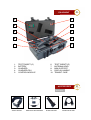
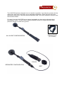
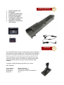
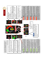
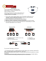
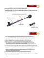
SHEARWATER TSCM Technical Surveillance Counter Measures Science and Innovation Centre Station X, Bletchley Park Sherwood Drive Milton Keynes MK3 6DS, UK Tel! Fax ! Mob ! Email! Web ! +44(0)1908 677062 +44(0)1908 230732 +44(0)7836 521376 [email protected] www.shearwatertscm.com LOCATOR XD 2.5 USER MANUAL v1 Jan 2011 CONTENTS SECTION ONE INTRODUCTION SECTION TWO FEATURES SECTION THREE EQUIPMENT SECTION FOUR ACCESSORIES SECTION FIVE CONFIGURATION SECTION SIX CONTROL MODULE SECTION SEVEN CHARGING SECTION EIGHT DISPLAY SECTION NINE HEADPHONES SECTION TEN ASSEMBLY SECTION ELEVEN TEST SECTION TWELVE PRINCIPLE SECTION THIRTEEN DISCOVERY SECTION FOURTEEN OPERATIONAL SECTION FIFTEEN TECHNICAL SECTION SIXTEEN HYGIENE 1 INTRODUCTION Our range of Non Linear Junction Detectors (NLJDs) were introduced in the mid 1980s for the detection of hidden electronic circuits. The product has undergone many development changes since it first appeared on the market. The LOCATOR incorporates the very latest technology in the Non-Linear Junction Detector evaluation. Designed for the detection, location and analysis of concealed passive or active electronic devices. Small, lightweight, robust and designed for the harshest of environments. The LOCATOR is an essential tool for electronic countermeasure searches, explosive ordinance disposal and a variety of security applications. The LOCATOR has been designed to the very highest standards in terms of functionality, ease of operation and reliability. As a result the LOCATOR offers a performance that is second to none in terms of quality, cost and operation. 2 • • • • • • • • • • • • FEATURES 2.5 GHz Operating frequency High transmit power Full colour touch screen display Automatic DSP power control Automatic frequency selection Single scroll wheel for major functions Simple user interface to enable quick evaluation of targets Dual harmonic discrimination logarithms to minimise false alarms Differential audio tones for Electronic and Corrosive evaluation Antenna head threat indicator Carbon fibre Integral extending arm Quick fit lithium-ion battery with fuel gauge 3 EQUIPMENT 1 6 2 7 3 8 4 9 5 10 1. 2. 3. 4. 5. TEST TARGET (C) BATTERY CHARGER CHARGER PSU CONTROL MODULE 6. 7. 8. 9. 10. TEST TARGET (E) ANTENNA HEAD ARM SUPPORT DISPLAY HANDLE TRANSIT CASE ACCESSORIES OPTIONAL ! ARM SUPPORT! WIRELESS HEADPHONES ! SPARE BATTERY ! SEPARATION LEAD 4 CONFIGURATION 5 The LOCATOR has been designed to be as versatile as possible. It provides the operator with the option of an ‘all-in-one’ single body unit or separated configuration. When using the unit in the separated configuration - using the optional separation lead - the control module is held by a body belt around the waist. For ease of use the LOCATOR has an integral extendable arm that can be adjusted without interrupting a search. The arm can be quickly extended to search for targets that have been placed in ceilings or buried in the ground. ARM SUPPORT (OPTIONAL) ʻALL-IN-ONEʼ CONFIGURATION POUCH SEPARATED CONFIGURATION BELT 1. 2. 3. 4. 5. 6. 7. 8. CONTROL MODULE 6 CHARGING 7 DATA CONNECTOR SPEAKER LITHIUM ION BATTERY EARPHONE SOCKET POUCH FASTENER STANDARD EARPHONES VOLUME CONTROL WIRELESS HEADPHONES (OPTIONAL) The LOCATOR battery charger automatically tests the battery at the beginning of each charge cycle. Supervision of the charging process is constantly monitored by an internal microprocessor. Place the battery into the battery bay ensuring that the 5-way connector is fully seated. The LEDs in the window will provide status information and the charger will automatically begin charging. To charge a totally flat battery will take up to 3 hours. LED Indication: Green flashing Green solid Red flashing Red solid Battery charging Battery fully charged Fuel gauge in need of recalibration Error ##################################^#!*,0#4"8+#7%$"47D27663#0+6+2$0# AUTO $*+#J@AKL#6+F+6#7'8#@-BS(#"%$9%$<#('2+#7#$7&=+$#*70# 5++'#8+$+2$+8#1,$*#7#0,='76#6+F+6#=&+7$+&#$*7'#HRMV#$*+# J@AKL#2"'$&"6#1,66#7%$"47D27663#8+2&+70+#$*+#6+F+6# 7'8#0+6+2$#?+7&2*#_#HLM#4"8+#&+783#;"&#\@A-@O# "9+&7D"'< # S e a r#c h 2 #########^#!*,0#4"8+#,'8,27$+0#$*+#$39+#";#$7&=+$# 8+$+2$+8#53#8,09673,'=#$*+#-A`J(.L??LB#0,='76#6+F+60#";#$*+ ['8#7'8#R&8#/7&4"',20<#S'#$*,0#4"8+#$*+#7%8,"#!(AL#,'2&+70+0# 9,$2*#70#$*+#LOL.!J(AS.#0,='76#6+F+6#&,0+0< Se 2 # # a r c h^#!*,0#4"8+#,'8,27$+0#$*+#$39+#";#$7&=+$# 8+$+2$+8#53#8,09673,'=#$*+#-A`J(.L??LB#0,='76#6+F+60#";#$*+# ['8#7'8#R&8#/7&4"',20<#S'#$*,0#4"8+#$*+#7%8,"#!(AL# ,'2&+70+0#9,$2*#70#$*+#.(JJ(?STL#0,='76#6+F+6#&,0+0< # # # Lis # # t e n F# M ^#!*,0#4"8+#8,096730#$*+# -A`J(.L??LB#R&8#/7&4"',2#0,='76#"'63<#S'#$*,0#4"8+#$*+# @-BS(#"%$9%$#,0#)JLU-LA.C#BL\(B-O@!LB< # # # Lis # # t e n A# M ^#!*,0#4"8+#8,096730#$*+# -A`J(.L??LB#R&8#/7&4"',2#0,='76#"'63<#S'#$*,0#4"8+#$*+# @-BS(#"%$9%$#,0#@\`OS!-BL#BL\(B-O@!LB< # # # L i#s t e n #I D # ^#S'#$*,0#4"8+#$*+#!&7'04,E+&#%0+0#7# )JLU-LA.C#\(B-O@!LB#$"'+#$*7$#,0#"9D4,0+8#;"&#$*+#6"'=# &7'=+#8+$+2D"'#";#!@JKL!0<#!*,0#4"8+#8,096730#$*+#-A`J(^ .L??LB#R&8#/7&4"',2#0,='76#"'63#7'8#$*+#@-BS(#"%$9%$#,0# )JLU-LA.C#BL\(B-O@!LB< # L i s t e# n I D ##########^#S'#$*,0#4"8+#$*+#!&7'04,E+&#%0+0#7# )JLU-LA.C#\(B-O@!LB#$"'+#$*7$#,0#"9D4,0+8#;"&#$*+#6"'=# &7'=+#8+$+2D"'#";#!@JKL!0<#!*,0#4"8+#8,096730#$*+#-A`J(^ .L??LB#['8#/7&4"',2#0,='76#"'63#7'8#$*+#@-BS(#"%$9%$#,0# )JLU-LA.C#BL\(B-O@!LB< # L i s t e#n A M ##########^#!*,0#4"8+#8,096730#$*+#-A`J(.L??LB# ['8#/7&4"',2#0,='76#"'63<#S'#$*,0#4"8+#$*+#@-BS(#"%$9%$#,0 @\`OS!-BL#BL\(B-O@!LB< # L i s t e#n F M #########^#!*,0#4"8+#8,096730#$*+#-A`J(.L??LB# ['8#/7&4"',2#0,='76#"'63<#S'#$*,0#4"8+#$*+#@-BS(#"%$9%$#,0 )JLU-LA.C#BL\(B-O@!LB< # S e a r#c h 1 #########^#!*,0#4"8+#,'8,27$+0#$*+#$39+#";#$7&=+$# 8+$+2$+8#53#.(\`@JSAK#$*+#['8#7'8#R&8#/7&4"',2#0,='76# 6+F+60<#S'#$*,0#4"8+#$*+#7%8,"#!(AL#,'2&+70+0#,'#9,$2*#70#$*+ LOL.!J(AS.#0,='76#6+F+6#&,0+0< S e# a r c h ##########^#!*,0#4"8+#,'8,27$+0#$*+#$39+#";#$7&=+$# 1 # 8+$+2$+8#53#.(\`@JSAK#$*+#['8#7'8#R&8#/7&4"',2#0,='76# 6+F+60<#S'#$*,0#4"8+#$*+#7%8,"#!(AL#,'2&+70+0#,'#9,$2*#70#$*+# .(JJ(?STL#0,='76#6+F+6#&,0+0< !"#2*7'=+#$*+#T(O-\L#6+F+6#";#$*+#09+7]+&#"&# +7&9*"'+0#%0+#$*+#!(-./#?.JLLA#5%E"'#$"#5&,'=#%9# $*+#0+6+2D"'#02&++'<#L,$*+,8+#$*+#7&&"1#"&#$"%2*# $*+#72$%76#F"6%4+#6+F+6#&+W%,&+8< !*+#JLB#0+=4+'$0#"'#$*+#8,09673#,'8,27$+#$*+#6+F+6#";# $*+#LOL.!J(AS.#0,='76<# !*+#6+F+6#,0#8+&,F+8# ;&"4#$*+#['8#*7&4"',2#&+2+,F+8#0,='76#0$&+'=$*# ,'8,27$"&#HJ??SM< !*+#Q@!!LJC#O(X#02&++'#1,66#799+7&#"'2+#766#$*+# 57&0#*7F+#+ID'=%,0*+8#7'8#1,66#7%$"47D27663#9"1+&# 8"1'#$*+#%',$#,'#YZ#0+2"'80< !"#$%&"'"()**"#$+,%-"&.%,/0.1" 2"#$%&"'"345"6$7$68.-" 9"#$%"""'"945"6$7$68.-" LOL.!J(AS.#\(BL#?LOL.!S(A \7'%76#J@AKL#0+6+2D"'#8,0^# 9673,'=#6+F+60#_#$"#_Z H47I,4%4M 8 !*+#57E+&3#0$&+'=$*#,'8,27$"9&0#8+2&+70+#70# 57E+&3#9"1++26,'+0< DISPLAY #.(JJ(?STL#\(BL#?LOL.!S(A !"#2*7'=+#$*+#"9+&7D'=#)JLU-LA.CV#%0+#$*+#!(-./# ?.JLLA#5%E"'#$"#5&,'=#%9#$*+#0+6+2D"'#02&++'<# L,$*+,8+#$*+#7&&"1#"&#$"%2*#$*+#72$%76#;&+W%+'23# &+W%,&+8< !*+#KJLLA#0+=4+'$0#"'#$*+#8,09673#,'8,27$+#$*+#6+F+6# ";#$*+#.(JJ(?STL#0,='76<##!*+#6+F+6#,0#8+&,F+8#;&"4# $*+#R&8#*7&4"',2#&+2+,F+8#0,='76#0$&+'=$*#,'8,27$"&# HJ??SM< !"#$%&'#())#$*+#%',$#!(-./#$*+#01,$2*#())#0345"6# 6"27$+8#,'#$*+#$"9#6+:#*7'8#2"&'+&#";#$*+#8,09673<#!*,0# 1,66#$*+'#5&,'=#%9#7#;%&$*+&++'#$"#2"'>&4#$*7$#$*+# "9+&7$"'$0#$"#$%&'#$*+#-',$#())<#!*+#%',$#1,66#="# ,'$"#?!@ABC#4"8+#%'D6#$*+#57E+&3#,0#&+4"F+8<#!*+# %0+�+G'=0#H+I2+9$#J@AKL#6+F+6M#1,66#5+#%987$+8# 7'8#4+4"&,N+8< !"#$%&'#(A#,'0+&$#7#57E+&3#7'8#1*+'#$*+#56%+#OLB# P70*+0#$*+#%',$#,0#,'#?!@ABQC#4"8+<#!%&'#(A#53# *"68,'=#8"1'#$*+#2+'$&+#5%E"'#;"&#R#0+2"'80< 9 HEADPHONES OPTIONAL The 2.4 GHz Wireless headphones have approximately 10 Hours of operational use before a charge is required. Please fully charge for more than 2 hours before use. The red LED is on when charging and off when the charging sequence is complete. 1. To turn ON - Press the power buttons on the Transmitter and Receiver for 4 seconds. The yellow LEDs will blink simultaneously at 5 second intervals indicating that they are operating correctly. 2. Plug the Transmitter into the operational LOCATOR unit . 3. Place the Receiver behind the neck and insert earbuds. 4. Adjust the volume as required by using the volume control on the (R) earbud. 5. The transmitter and receiver will turn themselves OFF automatically if no audio has been transmitted for over 5 minutes. TRANSMITTER! 1 2 ! 3 ! ! 4 1. CHARGING LED (RED). PAIRING LED (YELLOW) 2. POWER BUTTONS 3. MINI USB CHARGING SOCKET RECEIVER 2 1 3 4. AUDIO JACK 5. VOLUME UP/DOWN 6. 3D SOUND ON/OFF EARBUDS 5 6 To re-pair the Transmitter and Receiver. 1. Turn both devices OFF ( by holding down the power buttons for 2 seconds ) and then ON again ( by holding down the power buttons for 4 seconds ). 2. Press and hold both power buttons for 7 seconds until the LEDs blink rapidly, then release the buttons 3. Both LEDs should start to blink slowly and continue for 15 seconds to complete pairing. The LEDs should now be blinking simultaneously at 5 second intervals 10 ASSEMBLY Connect the ANTENNA and DISPLAY MODULE to the CONTROL MODULE by aligning the plug into the socket and lock by twisting the securing collar. Insert a charged BATTERY PACK into the CONTROL MODULE. Push the battery in until a positive connection is made. The blue standby LED should now be flashing indicating that the system is ready to turn ON. ANTENNA AND DISPLAY MODULE CONTROL MODULE ON BUTTON BATTERY PACK TEST 11 With a fully charged battery and assembly completed the test routine can begin. 1. Adjust the ANTENNA HEAD so that it is at right-angles to the handle. 2. Turn ON by holding down the centre button of the scroll wheel (indicated by the blue flashing LED) for 3 seconds and the DISPLAY panel will illuminate. 3. Set the RANGE to level 5 by pressing the (+) button on the scroll wheel. 4. Select SEARCH 1 - E mode by pressing the (E) button on the scroll wheel. 5. Test the system by aiming the white face of the ANTENNA HEAD approximately 20 cm away from the TEST TARGET (E). A positive response to the test target is an audible rising tone and a visible increase in signal strength. In practice the operator will find that a TEST TARGET becomes unnecessary as there are normally targets such as telephones and other equipment that provide satisfactory evidence of operation. 6. Adjust the VOLUME to a preferred level when using the TEST TARGET. 7. Move the ANTENNA away from any possible targets and select AUTO mode by momentarily pressing the centre button. 8. The unit is now operational and ready to begin searching for targets. Please note - If the unit is turned OFF by removing the battery without going into STANDBY mode, no user settings will be retained. 12 PRINCIPLE The LOCATOR combines extremely efficient radio transmission with reception of great sensitivity, and simultaneously analyses the signals at different, precisely determined frequencies. The intention is to trigger a reaction in targeted semiconductors. Semiconductors, transistors and diodes have the characteristic of responding to suitably defined radio waves and re-radiating at certain calculable frequencies. It therefore follows that if one can provide a signal and analyse the response, it is possible to indicate and appraise such items, know generally as non linear junctions. As all modern electronic circuitry contain semiconductors, the logic of searching by the technique is inescapable and it proves to be a most successful routine, provided that the equipment is well designed and manufactured to the very highest standard. It is important to recognize that neither the distance whence a reaction occurs nor its strength is any indication of the relevance or size of a discovered target; any response must be evaluated thoroughly. There is, however, no method of determining exactly what the discovered target circuitry may be - or whether it is innocent. Once an ELECTRONIC target response is indicated it follows that other examination and assessment be brought into play. The fundamental or original signal generated by the units transmitter may be re-radiated by the target on the Second Harmonic (twice the fundamental frequency) and this response is picked up by the first receiver. Similarly on the Third Harmonic ( three times the fundamental frequency) with the second receiver. Theory says a false target will display a higher signal level on the Third Harmonic (C) - CORROSIVE, whereas a true target, will show a stronger signal on the Second Harmonic (E) - ELECTRONIC. DISCOVERY To enhance the analysis of the return signals the LOCATOR automatically compares and evaluates whether an ELECTRONIC or CORROSIVE response has been detected. 13 DISCOVERY The process indicates the discovery of an ELECTRONIC target and careful use of the range control helps to locate its position. As the nature and the layout of the discovered device is unknown the exact pattern of the re-radiated signal cannot be forecast, but it is unlikely that the precise location will be far from that inferred by the antenna’s footprint. An actual physical examination of the area may be carried out, during which the device can be identified, its nature assessed and any threat it may pose may be considered. Varying the receivers and modes will enable the operator to assess the target for activity and some evidence of the nature of the discovered item. By selecting (E) ELECTRONIC and AM demodulation mode a beat, hum or even audio may be heard. If the target is genuine, but passive, it will still create a reaction that indicates an ELECTRONIC target. If a CORROSIVE target is found, it can be easily confirmed by selecting the AM demodulation mode and listening to the audio output. By knocking in the vicinity of the targeted area, a CORROSIVE target will produce a crackling sound that will be very unstable. Where as an ELECTRONIC target in AM mode will be completely silent and stable. As both receivers will be obtaining an incoming signal, there can be both ELECTRONIC and CORROSIVE in greater or lesser proportions showing at the same time. However the greater the CORROSIVE signal the more likely it is that the target is CORROSIVE and benign. Other security procedures must be applied, if the identified items remains suspect or, perhaps, incapable of further appraisal ( as when it is contained in a suitcase or in furniture) without further countermeasure or detection techniques. Standard operating Most operators will have metal detectors, radio transmitter discovery equipment and similar to assist them, but the value of LOCATOR is that it can silently locate powered or un-powered circuitry and thus discover passive inoperative and active devices. Common sense, operational knowledge and skills, plus additional equipment are always needed to make full use of LOCATOR and establish a successful pattern to the required defensive search process. OPERATIONAL 14 It is evident that LOCATOR does not claim, alone, to identify illicit devices. Operator counter surveillance skill and other related skills are essential to success and proficiency. Apart from occasions when the located response comes from an otherwise problematical source e.g. walling, which does not permit dismantling or assessment from other directions, the most probable practical difficulties arise from standing waves or false CORROSIVE targets. A standing wave, which effectively floods the reception, thus giving an apparently valid response, would not be common. In such circumstances the selection of a different operating frequency will overcome this problem. In the nature of things it is possible for a natural non linear junction to re-radiate in the manner of a real ELECTRONIC target, in what is often called “the rusty nail syndrome”. The design of LOCATOR makes it as immune as practical to such CORROSIVE targets and comparison of the harmonics helps discriminate between them. Natural non linear junctions are generally due to corrosion between metal and related substances. They can often be inhibited by breaking the contact between the materials with vibration or movement ( typically a knock on the surroundings with a soft headed hammer will do the trick ) during which the response will vary or “crackle”. Targets that are screened by metal can prevent or diminish signals; accordingly cupboards and containers should be examined open since the emissions may not penetrate. Heavily tarnished or corroded metal could also cause a false reaction. Should a target item be surrounded by metal ( in the form of a faraday cage ) it is unlikely to act as a competent radio device. Although, it would still require an external aerial to transmit its signal and this should allow it to be picked up by LOCATOR. The convenience and sensitivity of the LOCATOR minimises misleading indication though false readings that will alert the operator and bring his expertise into use. An experienced operator and LOCATOR together will usually mark and assess any threatening responses. Please contact you supplier for further information and training. 15 TECHNICAL Transmi=er Power output Adjustable from Frequency range Signal type ModulaJon Receiver 1 Audio output DemodulaJon SensiJvity Frequency range Receiver 2 Audio output Auto or manual control. 2 mW to 2W or 4W ERP (0 to 33 or 36 dBm ERP). 10 spot frequencies within 2410-‐2485MHz. CW. Selectable FM , 1KHz tone (Listen ID mode). (E) Electronic -‐ 2nd Harmonic. 5 Selectable modes linked to speaker or headphones. AM, FM and Tone. DetecJon at -‐133 dBm 4.820 to 4.970 GHz. DemodulaJon SensiJvity Frequency range (C) Corrosive -‐ 3rd Harmonic. 5 Selectable modes linked to speaker or headphones. AM, FM and Tone. DetecJon at -‐133 dBm. 7.230 to 7.455 GHz. Display Screen Type Viewing angle LifeJme AMOLED – AcJve Matrix 180 Degrees. 55,000 Hours. Controls Display Handle 16 5 way scroll wheel. Screen InformaHon Range Graphical Modes Touch screen Antenna Frequency coverage Auto or Manual operaJon. (E) and (C) signal levels. Search 1, Search 2, Listen FM. Listen AM and Listen ID. Volume, Frequency & Turn Off. PolarisaJon 2400 -‐2500 MHz 4800-‐5000 MHz 7200-‐7500 MHz Circular. Wireless Headphones Range Run Jme Control Up to 8 metres. 8 hours. Volume Up/Down,3D,On/Off. Ba=ery Charger Type Input voltage Charge current CommunicaJon Charge Jme LEDS Smart technology. 90 -‐ 260 VAC, 2.5A DC Variable up to 2.0A SMBus. Approximately 2.5 hrs. Charging status. Ba=ery Type Capacity RunJme Indicator Lithium-‐Ion. 5000 mAH Approx. 4hrs (2W unit). 4 barfuel gauge HYGIENE The LOCATOR is maintenance free and must not be opened without workshop knowledge and supplier advice, otherwise any warranty will be deemed invalid The operator is requested not to alter any component or module as without accurate measurement equipment, the critical set up of the instruments power and sensitivity will be altered detrimentally. Ensure that all plugs and connections are kept free of dirt and foreign matter. Keep your charger in a dry place. The charger should be disconnected from the mains when not in use. Batteries can explode, leak or catch on fire if exposed to high temperature. Do not open or dismantle. Rechargeable batteries are not to be disposed of as domestic waste. Surrender used batteries to your dealer or a battery collecting point. Supplied by SHEARWATER TSCM Station X Innovation Centre Bletchley Park Sherwood Drive Milton Keynes MK3 6DS United Kingdom Tel: (IDD 44) (0)1908 677062 Fax: (0)1908 230732 Email: [email protected] Web: www.shearwatertscm.com