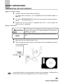
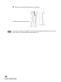
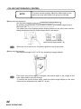
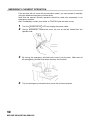
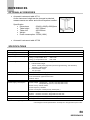
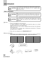
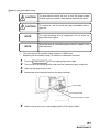
1
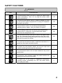
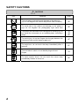
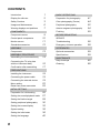
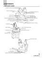
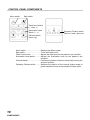
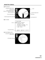
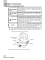
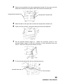
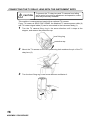
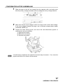
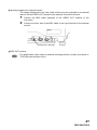
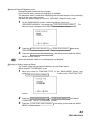
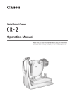
INSTRUCTION MANUAL
NON-MYDRIATIC RETINAL CAMERA
TRC-NW6S
INTRODUCTION
Thank you for purchasing the TOPCON TRC-NW6S Non-Mydriatic Retinal
Camera.
This machine has the following innovative features:
• Can observe the fundus of the eye and take images without using mydriatics.
• The quality of pictures has improved and this instrument is easier to operate
than previous models.
• Can easily take images of the periphery using the alignment point and the
external fixation target for peripheral photography.
This manual outlines the TRC-NW6S Non-Mydriatic Retinal Camera, including
operation procedures, troubleshooting, maintenance and cleaning.
Before using, carefully read the “DISPLAY FOR SAFE USE” and the “SAFETY
CAUTIONS” to familiarize yourself with the features of the TRC-NW6S NonMydriatic Retinal Camera and use it efficiently and safely.
Always keep this Instruction Manual at hand.
PRECAUTIONS
• Since this machine is a precision instrument, be sure to install and use it in a
controlled environment under normal temperature, humidity and atmospheric
pressure conditions (10~40°C, 30-85%, 70~106kPa) and avoid direct exposure
to sunlight.
• Never install the machine on a slope or a place with vibrations.
• Before using the machine, make sure that all cables are correctly connected.
• Use a power supply within the range of ±10% of the rated voltage (50/60Hz).
• Keep the installation place always clean, and when not in use, turn off the
Power switch, cap the objective lens, and install the dust cover.
• To ensure good imaging results, handle the objective lens with particular care
and keep it free of flaws, fingerprints, stains and dusts.
1
DISPLAY FOR SAFE USE
To encourage safe and proper use and to prevent danger to the operator and others or potential
damage to properties, important messages are put on the instrument body and inserted in the
instruction manual.
We suggest that everyone understand the meaning of the following displays, icons and text
before reading the “SAFETY CAUTIONS” and observe all listed instructions.
DISPLAYS
Display
Meaning
WARNING
Incorrect handling by ignoring this display may lead to an
impending danger of death or serious injury.
CAUTION
Incorrect handling by ignoring this display may lead to
personal injury or physical damage.
• Injury refers to hurt, burns, electric shock, etc. which does not require hospitalization
or extended medical treatment.
• Physical damage refers to extensive damage to the building, nearby equipment
and/or surrounding furniture.
ICONS
Icon
Meaning
Prohibition.
Specific content is expressed with words or a picture near the
icon.
Mandatory Action
Specific content is expressed with words or a picture near the
icon.
Caution
Specific content is expressed with words or a picture near the
icon.
2
SAFETY CAUTIONS
WARNINGS
Icon
Prevention item
Page
To avoid electric shock, be sure to unplug the power cable
before assembling. Also, do not plug the power cable
before assembling.
14
To avoid fire and electric shock in case of leakage, be sure
to use a power supply equipped with a 3-plug AC receptacle
for proper grounding.
19
To avoid electric shock, do not attempt disassembling,
rebuilding and/or repairs. Ask your dealer for repairs.
56
To avoid electric shock do not remove body components,
covers of the TV relay lens, chinrest and power supply. –
other than the lamp house cover.
56
To avoid electric shock, be sure to remove the power cable
from the instrument body before removing the fuse cover.
Also, do not connect the power cable to the instrument body
with the fuse cover left unfixed.
64
To avoid fire and electric shock, install the instrument in a
place free from water and other liquids.
—
To avoid fire and electric shock, do not put cups and
vessels containing liquids near the instrument.
—
To avoid electric shock, do not insert metals into any vents
and/or slots.
—
To avoid fire, use a properly rated fuse which matches the
display provided on the fuse holder.
64
To avoid fire in the event of instrument malfunction,
including smoke, immediately turn OFF the Power switch
and unplug the cable.
—
3
SAFETY CAUTIONS
CAUTIONS
Icon
4
Meaning
Page
To avoid pain to the patient and damage to the patient’s
eye, do not brighten the monitor lamp more than necessary.
45
To avoid pain to the patient and damage to the patient’s
eye, do not brighten the photography light more than
45
To prevent the instrument from falling and to avoid injury, do
not install the instrument on an unstable place, including a
slope.
14
18
60
To avoid injury, do not put fingers into the gap between the
instrument body and the power supply unit.
47
To avoid burn, do not touch the lamp immediately after it
goes off.
61
To avoid electric shock, do not handle plugs with wet
fingers
19
To avoid electric shock, do not touch the xenon lamp
immediately flashes or burns out.
62
SAFETY CAUTIONS
CAUTIONS
Icon
Meaning
Page
To avoid injury to the patient’s face and hands, be sure to
operate the chinrest for height adjustment while directly
watching the patient.
41
To avoid injury to the patient’s eyes and nose while moving
the instrument body, be attentive of the distance between
the patient and the objective lens.
47
To prevent the TV relay lens and TV camera from falling
and to avoid injury during adjustment and operation, make
sure they are surely mounted.
To avoid falling and injury while moving the table with the
instrument on top of it, be sure to use an approved
automatic instrument table.
16
18
To prevent the instrument from falling and to avoid injury
during carrying, be sure to secure the instrument with the
fixing knob at the bottom.
18
To avoid injury during carrying, be sure to hold the instrument body
at the bottom with two persons. Carrying by one person may
cause backache or injury by falling. Holding at areas other than the
bottom may also cause pinching fingers and injury, as well as
falling, thereby causing damage to the instrument.
14,18
To prevent the TV camera from falling and to avoid injury,
make sure that the camera mount lever is firmly tightened.
60
To prevent the TV relay lens from falling and to avoid injury,
make sure that the lens mount lever is firmly tightened.
60
To avoid electric shock, be sure to turn the power supply off
and unplug the power cable before replacing the lamp.
61,62
To prevent the instrument body from falling and to avoid
injury during movement, be sure to fix the power supply unit
with the instrument body using the base locking knob.
—
5
USAGE AND MAINTENANCE
Usage:
• The TRC-NW6S Non-Mydriatic Retinal Camera is an electric instrument for
medical use. Use this instrument under a doctor’s guidance.
USER MAINTENANCE:
To ensure the safety and performance of the instrument, all maintenance work,
unless specified in this manual, shall be conducted by trained service engineers.
The following maintenance tasks may be done by the user.
For details, see the relevant part of this manual.
Replacing lamps:
The illumination lamp and xenon lamp may be replaced by the user. For details, see
“Replacing the illumination lamp” on page 61 and “Replacing the xenon lamp” on
page 62.
Replacing fuses:
Fuses of the instrument body may be replaced by the user.
“Changing the fuses” on page 64.
Cleaning the objective lens:
The objective lens may be cleaned by the user.
objective lens” on page 66.
For details, see
For details, see “Cleaning the
ESCAPE CLAUSES
• TOPCON shall not take any responsibility for damage due to fire,
earthquakes, actions by third persons and other accidents, or damage due to
negligence and misuse by the user and any use under unusual conditions.
• TOPCON shall not take any responsibility for damage derived from inability to
properly use this instrument, such as loss of business profit and suspension of
business.
• TOPCON shall not take any responsibility for damage caused from using this
instrument in a manner other than that described in this Instruction Manual.
• Diagnoses made shall be the responsibility of pertaining doctors and
TOPCON shall not take any responsibility for the results of such diagnoses.
6
WARNING DISPLAYS AND POSITIONS
To ensure safety, the machine provides warning displays.
Use the instrument correctly by observing the display instructions. If any of the
following display labels are missing, contact your dealer of TOPCON at the address
stated on the back cover.
CAUTION
• To avoid injury to the patient’s face and hands,
be sure to operate the chinrest for height
adjustment while directly watching the patient.
CAUTION
• To avoid potential injury during operation,
do not touch the patient’s eyes or nose
with the instrument.
WARNING
• Electrical shock may cause burns or possible fire.
Turn the main power switch OFF and UNPLUG
the power cord before replacing fuses. Replace
only with fuses of the correct rating.
CAUTION
• To avoid electric shock, be sure to turn
the power supply off and unplug the
power cable before replacing the lamp.
• To avoid burn, do not touch the lamp
immediately after it goes off.
WARNING
WARNING
• Electrical shock may cause burns or possible
fire. Turn the main power switch OFF and
UNPLUG the power cord before replacing
fuses. Replace only with fuses of the correct
rating.
• To prevent electrical shock, do not remove
cover.
No user serviceable parts inside, refer
servicing to qualified personnel.
7
CONTENTS
Introduction
Display for safe use
Safety Cautions
Usage and Maintenance
Warning displays and positions
1
2
3
6
7
Control panel components
Monitor screen
Standard accessories
9
10
11
12
ASSEMBLY
Components
Connecting the TV relay lens
with the instrument body
Confirmation after assembling
13
Connecting the power cable
Connecting the external device
Menu setting
Reset from power save state
14
Setting the record/playback mode
Setting the fixation target
Setting peripheral photography
Setting the screen display
System setting
Setting the initial state
Setting the language
8
Anterior segment photography
BEFORE REQUESTING
SERVICE
Troubleshooting
Emergency chinrest operation
Optional accessories
56
58
16
17
18
19
19
22
25
26
27
28
30
32
35
36
40
59
59
MAINTENANCE
Daily checkups
INITIAL SETTING
Preparation for initial setting
Peripheral photography
Specifications
PREPARATIONS
Installing the instrument
Color photography (Center)
41
44
52
54
55
REFERENCES
ASSEMBLY PROCEDURE
Assembling the instrument body
Preparation for photography
Finishing
COMPONENTS
Component names
BASIC OPERATIONS
Cleaning
60
66
COMPONENTS
COMPONENT NAMES
TV camera connection terminal
Diopter compensation lens
selector
TV relay lens attaching lever
TV relay lens
Angle selector
Focusing knob
Name plate slot
Color video monitor
Photography switch
Omni-directional joystick
IR filter selector
Image quality adjustment knob
Base brake knob
Vertical position mark
Control panel
Power lamp
Fuse holder
Fixing knob (for carrying)
Forehead rest
Anterior segment fixation target
Canthus marker
Objective lens
Lamp house cover screw
Chinrest tissue pin
Chinrest
Lamp house cover
External fixation target
Base
Power switch
Fuse holder
Power supply unit
External connection terminal
9
COMPONENTS
CONTROL PANEL COMPONENTS
Menu switch
Split switch
Flash Level switch
(–, reset, +)
Illumination Level
switch (–, +)
Periphery Fixation switch
(left turn, reset, right turn)
Chinrest switch
(down, up)
Menu switch .............................. Displays the Menu screen.
Split switch ................................ Turns split lines on/off.
Flash Level switch .................... Adjusts the flash level for the patient’s eye condition.
Illumination Level switch ........... Adjusts the illumination level for the patient’s eye
condition.
Chinrest switch ......................... Positions the patient’s head by electrically moving the
chinrest up/down.
Periphery Fixation switch.......... Switches the position of the internal fixation target to
guide the patient’s eye to the periphery fixation point.
10
COMPONENTS
MONITOR SCREEN
Monitor screen
Nameplate/Fixation target
position data
( ) scale
Xenon charging display
Flash level compensation display
Flash level display
Picture angle display
Fixation target position display
Alignment bright spots
Split lines
Illumination level
Menu screen
Cursor
Input guide display
Preview display (color)
Nameplate/ Fixation target
position data
Photography image
11
COMPONENTS
STANDARD ACCESSORIES
Upon unpacking, make sure that all the following standard accessories are delivered. Figures in
( ) are the quantities
Power cable (1)
Nameplate (10)
Illumination lamp (1)
Fuse (9)
Chinrest tissue (1)
Chinrest tissue pin (2)
Emergency chinrest knob (1)
Spare parts case (1)
Instruction Manual
Warranty (1)
Dust cover (1)
External fixation target (1)
TV camera power cable (1)
TV camera signal cable (1)
12
COMPONENTS
ASSEMBLY
COMPONENTS
(1) (2)
(3)
(6)
(4)
(7)
(5)
(9)
(11)
(14)
(10)
(12)
(15)
(8)
(17)
(18)
(19)
(16)
(13)
Description
(1) Instrument body
(2) TV relay lens
(3) Rail cover
(4) TV camera power cable
(5) TV camera signal cable
(6) Power cable
(7) External fixation target
(8) Star screwdriver
(9) Hexagon rod spanner
(10) Focusing tool
Quantity
1
1
2
1
1
1
1
1
1
1
(20)
Container
O
O
O
O
O
O
O
O
O
Spare parts case
Description
(11) Dust cover
(12) Spare part case
(13) Illumination lamp
(14) Nameplate
(15) Fuse (spare)
(16) Chinrest tissue
(17) Chinrest tissue pin (spare)
(18) Emergency chinrest knob
(19) TRC-NW6SF Instruction Manual
(20) Warranty
Quantity
1
1
1
10
9
1
2
1
1
1
Container
O
O
Spare parts case
Spare parts case
Spare parts case
Spare parts case
Spare parts case
Spare parts case
O
O
13
ASSEMBLY
ASSEMBLY PROCEDURE
ASSEMBLING THE INSTRUMENT BODY
1
2
WARNING
To avoid electric shock, be sure to unplug the power cable
before assembling. Also, do not plug the power cable
before assembling.
CAUTION
To prevent the instrument from falling and to avoid injury,
do not install the instrument on an unstable place,
including a slope.
CAUTION
To avoid injury during carrying, be sure to hold the
instrument body at the bottom with two persons. Carrying
by one person may cause backache or injury by falling.
Holding at areas other than the bottom may also cause
pinching fingers and injury, as well as falling, thereby
causing damage to the instrument.
NOTE
Since the upper part and lower part of the instrument body
are merely connected with the power cable, take them out
together so they do not separate from each other.
Take out the instrument body (1) from the container and put it on the table.
Slightly raise the omni-directional joystick, and pull out the cushion from the
lower part of the base in the arrow direction.
Omni-directional
joystick
sponge
styrofoam
sponge
cushion
3
Wipe the sliding board with a cloth to remove dirt.
14
ASSEMBLY PROCEDURE
4
Remove the styrofoam from the transportation bracket (A), the one on the left
hand side viewed from the patient side, and unscrew the bracket (B).
transportation bracket (A)
5
6
7
8
transportation bracket (B)
Slide the base to the right and unscrew the transportation bracket (A).
Fasten the rail covers(3), using the small screws that are attached.
Set the external fixation target (7). Match the connector groove of the
external fixation target (7) with the connector of the instrument body and
insert it. Secure it firmly so that it does not move.
Fix the chinrest tissue(16) with the chinrest tissue pin.
chinrest tissue pin
chinrest tissue
15
ASSEMBLY PROCEDURE
CONNECTING THE TV RELAY LENS WITH THE INSTRUMENT BODY
CAUTION
To prevent the TV relay lens and TV camera from falling
and to avoid injury during adjustment and operation, make
sure they are surely mounted.
This machine is connected and used with an optional TV camera.
If your TV camera is SONY DXC-970MD, the attached TV camera power cable (4)
and TV camera signal cable (5) can be connected to the instrument body (1).
1
Turn the TV camera fixing ring in the arrow direction until it stops at the
stopper, and remove the protective cap.
lens fixing ring
protective cap
2
3
Mount the TV camera so the lens positioning hole matches the pin of the TV
relay lens (2).
Turn the lens fixing ring in the arrow direction and fasten it.
16
ASSEMBLY PROCEDURE
CONFIRMATION AFTER ASSEMBLING
1
2
3
Slide the base to the left, as viewed from the operator side, and make sure
that the primary voltage coincides with the voltage as set by voltage selector.
Make sure that the input voltage is within the range ±10% of the rated voltage.
If the input voltage exceeds the range, use a constant-voltage power supply
(marketed: 400VA up).
Loosen the base locking knob, and move the omni-directional joystick to
confirm that it moves smoothly.
1) Right-left movement
2) Back-forth movement
3) Up-down movement
Just after being unpacked, the right-left movement may be uneven. If so, move the
joystick with force to its limits in all directions.
17
ASSEMBLY PROCEDURE
PREPARATIONS
INSTALLING THE INSTRUMENT
CAUTION
To prevent the instrument from falling and to avoid injury
during carrying, be sure to secure the instrument with the
fixing knob at the bottom.
CAUTION
To avoid injury during carrying, be sure to hold the
instrument body at the bottom with two persons. Carrying
by one person may cause backache or injury by falling.
Holding at areas other than the bottom may also cause
pinching fingers and injury, as well as falling, thereby
causing damage to the instrument.
CAUTION
To avoid falling and injury while moving the table with the
instrument on top of it, be sure to use an approved
automatic instrument table.
To prevent the instrument from falling and to avoid injury,
do not install the instrument on an unstable place,
including a slope.
Fasten the fixing knob.
CAUTION
1
2
Firmly hold the instrument body at the specified positions, and put it on the
automatic instrument table.
For details about the automatic instrument table, see “OPTIONAL
ACCESSORIES” on page 59.
Fixing knob
Holding positions
3
18
PREPARATIONS
Holding the instrument body
After installing the instrument, fully loosen the fixing knob.
The instrument body is freed to move.
4
If the instrument body is slightly off level, fine-adjust the height by properly
operating the four adjusters.
Do not extend the adjuster past 1cm.
Adjuster
CONNECTING THE POWER CABLE
1
2
3
WARNING
To avoid fire and electric shock in case of leakage, be sure
to use a power supply equipped with a 3-plug AC
receptacle for proper grounding.
CAUTION
To avoid electric shock, do not handle plugs with wet
fingers.
Make sure that the
POWER SWITCH
of the instrument body is OFF.
Attach the power cable to the instrument body.
Plug the power cable into the 3-p AC receptacle with grounding.
CONNECTING THE EXTERNAL DEVICE
Connecting the TV camera
This machine is connected and used with an optional TV camera.
If your TV camera is SONY DXC-970MD, the attached TV camera power cable
and TV camera signal cable can be connected to the instrument body.
1
Connect the TV camera connection terminal of the instrument body and the
DC IN/REMOTE terminal of the TV camera with the TV camera power cable.
19
PREPARATIONS
2
Connect the TV camera connection terminal of the instrument body and the
RGB/SYNC terminal of the TV camera with the TV camera signal cable.
DC IN/REMOTE terminal
RGB/SYNC terminal
TV camera
(SONY DXC-970MD)
If your TV camera is not a SONY DXC-970MD, contact your dealer or TOPCON
(see the back cover) for details about connection.
Connecting the external recording device
This machine can connect an external recording device via the external
connection terminal.
1
2
3
Connect an image cable (optional) of the external recording device to the
image connection terminal of the instrument.
Connect a control cable (optional) from the external recording device to the
control terminal of the instrument.
For a use with a TOPCON IMAGEnet system, connect the photography data
cable (optional) to the photography data output terminal of the instrument.
Image connection terminal
Control terminal
Photography data output terminal
For connection with external recording devices, various types of connection cables
are prepared.
For details about connecting external recording devices, contact your dealer or
TOPCON (see the back cover).
20
PREPARATIONS
Outputting images to an external monitor
The images displayed on the color video monitor may be outputted to an external
monitor via the VIDEO OUT terminal of the external connection terminal.
1
2
Connect the BNC cable (optional) to the VIDEO OUT terminal of the
instrument.
Connect the other end of the BNC cable to the input terminal of the external
monitor.
VIDEO OUT terminal
VIDEO OUT terminal
For details about video output to external recording devices, contact your dealer or
TOPCON (see the back cover).
21
PREPARATIONS
MENU SETTING
In menu setting, record/playback, fixation target on/flicker, internal/external fixation
targets, fixation target patterns and flash level can be set.
Preparation for menu setting
1
2
Check the power cable connection.
For details about the connection, see “Connecting the power cable” on page
12.
Turn the
POWER SWITCH
ON.
Displaying the menu screen
1
2
Check the monitor screen.
Press the MENU SWITCH of the control panel.
Check the “MAIN MENU” screen.
Cursor
3
Press the
moves.
FLASH LEVEL SWITCH (+)
Returning to the Monitor screen
1
22
PREPARATIONS
Press the
MENU SWITCH
.
or
FLASH LEVEL SWITCH (-)
; the cursor
Setting the Record/Playback mode
Record/Playback modes can be changed.
In the Record mode, ordinary photography is available.
The playback mode is used when displaying the recorded images of the recording
device to the color video monitor.
Just after the power supply is turned on, “RECORD” (Record mode) is set.
1
2
3
On the "MAIN MENU" screen, make sure that the cursor is at
“RECORD/PLAYBACK”, and press the FLASH LEVEL SWITCH (RESET) . The
Monitor screen changes to the “RECORD/PLAYBACK” screen.
Press the FLASH LEVEL SWITCH (+) or FLASH LEVEL SWITCH (-) and select
“RECORD” (Record mode) or “PLAYBACK” (Playback mode).
Press the FLASH LEVEL SWITCH (RESET) ; the setting is done and the “MAIN
MENU” screen returns.
When the playback mode is on, photography is prohibited.
Switching of fixation target on/flicker
The fixation target can be switched between on and flicker states.
When shipped, “FLICKERING” is set.
1
Move the cursor to “FIXATION TYPE” on the “MAIN MENU” screen, and
pressFLASH
the LEVEL SWITCH (RESET)
to call out the “FIXATION TYPE”
screen.
2
3
Press the FLASH LEVEL SWITCH (+) or FLASH LEVEL SWITCH (-) and select
“CONSTANT” (on) or “FLICKERING” (flicker).
Press the FLASH LEVEL SWITCH (RESET) ; the setting is done and the “MAIN
MENU” screen returns.
23
PREPARATIONS
Switching of internal/external fixation targets
Internal/external fixation targets can be switched.
When shipped, “INTERNAL” (internal fixation) is set.
1
2
3
Move the cursor to “INTERNAL/EXTERNAL FIX” on the “MAIN MENU”
screen, and press the FLASH LEVEL SWITCH (RESET) to call out the
“INTERNAL/EXTERNAL FIX” screen.
Press the FLASH LEVEL SWITCH (+) or FLASH LEVEL SWITCH (-) and select
“INTERNAL” (internal fixation) or “EXTERNAL” (external fixation).
Press the FLASH LEVEL SWITCH (RESET) ; setting is done and the “MAIN
MENU” screen returns.
Fixation target pattern
You can select a fixation target pattern.
When shipped, “8” is set.
1
2
Move the cursor to “FIXATION PATTERNS” on the “MAIN MENU” screen,
FLASH LEVEL SWITCH (RESET)
and press the
to call out the “FIXATION
PATTERNS” screen.
Press the FLASH LEVEL SWITCH (+) or FLASH LEVEL SWITCH (-)
desired pattern from the following:
“4A” (vertical-horizontal 4 positions),
“4B” (diagonal 4 positions),
“5A” (vertical-horizontal 4 positions + center),
“5B” (diagonal 4 positions + center),
“8” (8 positions), or
“9” (8 positions + center).
and select the
The “center” position is assigned to the optical axis center and is used for
photographing around the macular segment.
24
PREPARATIONS
3
Press the FLASH LEVEL SWITCH (RESET) ; setting is done and the “MAIN
MENU” screen returns.
Flash level
You can change the reference value of the flash level.
When shipped, “0” (no change) is set.
1
Select “FLASH LEVEL” on the “MAIN MENU” screen, and press the
FLASH LEVEL SWITCH (RESET)
2
3
to call out the “FLASH LEVEL” screen.
Press the FLASH LEVEL SWITCH (+) or
desired level from the following:
“+2” (2 steps up),
“+1” (1 step up),
“0” (no change),
“-1” (1 step down), or
“-2” (2 steps down).
FLASH LEVEL SWITCH (-)
and select the
Press the FLASH LEVEL SWITCH (RESET) ; setting is done and the “MAIN
MENU” screen returns.
A step up/down changes the flash level reference value by about 20%.
RESET FROM POWER SAVE STATE
This machine adopts the power save method for power saving.
When the instrument body is not operated within a set time, the power save
function stops power supply to the monitor, CCD camera, illumination light source
and photography light source.
When power save sets in, the power lamp of the control panel flickers and the
monitor screen goes off.
1
Press the PHOTOGRAPHY SWITCH .
In a few seconds, the video monitor is displayed to be ready for
photographing.
When shipped, the power save set time is 10 minutes.
To change the set time, contact your dealer or TOPCON (see the back cover).
25
PREPARATIONS
INITIAL SETTING
On the "INITIAL MENU" screen, settings such as record/playback, internal/external
fixation targets, peripheral photography, system setting, initial setting and
language can be programmed.
PREPARATION FOR INITIAL SETTING
1
2
Make sure that the power cable is connected.
Press the
MENU SWITCH
and turn the
Press the
sounds.
and
POWER SWITCH
MENU SWITCH
and
PHOTOGRAPHY SWITCH
of the control panel
ON.
PHOTOGRAPHY SWITCH
until the buzzer
The Title screen is displayed, and in a few seconds the Monitor screen is
displayed.
3
4
Press the Menu switch of the control panel; the “INITIAL MENU” screen is
displayed.
To finish the “INITIAL MENU” screen, press the
MENU SWITCH
.
When the POWER SWITCH is turned OFF without finishing the “INITIAL MENU”
screen, the settings are not changed.
26
INITIAL SETTING
SETTING THE RECORD/PLAYBACK MODE
The Record/Playback mode can be changed.
The playback mode is used when displaying the recorded images of the recording
device to the color video monitor.
Just after turning the power supply on, “RECORD” (Record mode) is set.
1
2
3
Move the cursor to the “RECORD/PLAYBACK” of the “INITIAL MENU”
screen, and press
theLEVEL SWITCH (RESET)
. The Monitor screen
FLASH
changes to the “RECORD/PLAYBACK” screen.
Press the FLASH LEVEL SWITCH (+) or
“RECORD” or “PLAYBACK” mode.
Press the FLASH LEVEL SWITCH (RESET)
called back.
FLASH LEVEL SWITCH (-)
and select the
and the “INITIAL MENU” screen is
When the POWER SWITCH is turned OFF without finishing the “INITIAL MENU”
screen, the settings are not changed.
27
INITIAL SETTING
SETTING THE FIXATION TARGET
On the “FIXATION” screen, fixation target on/flicker and internal/external fixation
target switching can be set.
1
On the “INITIAL MENU” screen, move the cursor to “FIXATION,” and press
the FLASH LEVEL SWITCH (RESET) . The Monitor screen changes to the
“FIXATION” screen.
MENU SWITCH
When the POWER SWITCH is turned OFF without finishing the “INITIAL MENU”
screen, the settings are not changed.
2
To finish the “ FIXATION” screen, press the
.
Switching of fixation target on/flicker
The fixation target can be switched between on and flicker states. When shipped,
“FLICKERING” (flicker) is set.
1
2
3
28
INITIAL SETTING
Select “FIXATION TYPE” on the “FIXATION” screen and call out the
“FIXATION TYPE” screen.
Press the FLASH LEVEL SWITCH (+) or FLASH LEVEL SWITCH (-) and select
“CONSTANT” (on) or “FLICKERING” (flicker).
Press the FLASH LEVEL SWITCH (RESET) ; setting is done and the “MAIN
MENU” screen returns.
Switching of internal/external fixation targets
Internal/external fixation targets can be switched. When shipped, “INTERNAL”
(internal fixation) is set.
1
2
3
Select “INTERNAL/EXTERNAL FIX” on the “FIXATION” screen, and call out
the “INTERNAL/EXTERNAL FIX” screen.
Press the FLASH LEVEL SWITCH (+) or FLASH LEVEL SWITCH (-) and select
“INTERNAL” (internal fixation) or “EXTERNAL” (external fixation).
Press the FLASH LEVEL SWITCH (RESET) ; setting is done and the “INITIAL
MENU” screen returns.
29
INITIAL SETTING
SETTING PERIPHERAL PHOTOGRAPHY
On the “PERIPHERAL FIXATION” screen, settings such as fixation target pattern,
R/L reset and display mode can be programmed.
1
Move the cursor to the “PERIPHERAL FIXATION” of the “INITIAL MENU”
screen, and press the FLASH LEVEL SWITCH (RESET) . The monitor screen
changes to the “PERIPHERAL FIXATION” screen.
MENU SWITCH
When the POWER SWITCH is turned OFF without finishing the “INITIAL MENU”
screen, the settings are not changed.
2
To finish the “PERIPHERAL FIXATION” screen, press the
.
Fixation target pattern
You can select a fixation target pattern. When shipped, “8” is set.
1
2
30
INITIAL SETTING
Move the cursor to “FIXATION PATTERNS” on the “PERIPHERAL
FIXATION” screen, and call out the “FIXATION PATTERNS” screen.
Press the FLASH LEVEL SWITCH (+) or FLASH LEVEL SWITCH (-) and select the
desired pattern from the following:
“4A” (vertical-horizontal 4 positions),
“4B” (diagonal 4 positions),
“5A” (vertical-horizontal 4 positions + center),
“5B” (diagonal 4 positions + center),
“8” (8 positions), or
“9” (8 positions + center).
3
Press the FLASH LEVEL SWITCH (RESET) ; the setting is done and the
“PERIPHERAL FIXATION” screen returns.
The “center” position is assigned to the optical axis center and is used for
photographing around the macular segment.
R/L reset
When the base is moved in the middle of a peripheral photography, right/left eye
reset can be set. (When OFF is set, peripheral photography cannot be reset by
right/left eye switching.) When shipped, “OFF” (no reset) is set.
1
2
3
Select “R/L RESET” on the “PERIPHERAL FIXATION” screen, and call out
the “R/L RESET” screen.
Press the FLASH LEVEL SWITCH (+) or
“ON” (reset) or “OFF” (no reset).
FLASH LEVEL SWITCH (-)
and select
Press the FLASH LEVEL SWITCH (RESET) ; the setting is done and the
“PERIPHERAL FIXATION” screen returns.
Display mode
The display mode of peripheral fixation target can be set. When “FIXATION
POSITION” (fixation position display) is set, the monitor screen display responds
to the fixation target, and when “PHOTOGRAPHIC POSITION” (picture position
display) is set the monitor screen display responds to the photography result.
When shipped, “FIXATION POSITION” (fixation position display) is set.
1
2
Select “FIXATION INDICATOR” on the “PERIPHERAL FIXATION” screen,
and call out the “FIXATION INDICATOR” screen.
Press the FLASH LEVEL SWITCH (+) or FLASH LEVEL SWITCH (-) and select
“FIXATION POSITION” (fixation position display) or “PHOTOGRAPHIC
POSITION” (picture position display).
31
INITIAL SETTING
3
Press the FLASH LEVEL SWITCH (RESET) ; the setting is done and the
“PERIPHERAL FIXATION” screen returns.
SETTING THE SCREEN DISPLAY
On the “MONITOR DISPLAY” screen, display settings such as flash level
compensation, flash level, illumination level, picture angle and fixation position can
be set.
1
Make sure that the cursor is on the “MONITOR DISPLAY” of the “INITIAL
MENU” screen, and press the FLASH LEVEL SWITCH (RESET) . The Monitor
screen changes to the “MONITOR DISPLAY” screen.
2
To finish the “MONITOR DISPLAY” screen, press the
MENU SWITCH
.
When the POWER SWITCH is turned OFF without finishing the “INITIAL MENU”
screen, the settings are not changed.
Flash level compensation display
The flash level compensation display can be set. When shipped, “ON” (display) is
set.
1
2
3
32
INITIAL SETTING
Select “FLASH LEVEL IN 5STEPS” on the “MONITOR DISPLAY” screen, and
call out the “FLASH LEVEL IN 5STEPS” screen.
Press the FLASH LEVEL SWITCH (+) or
“ON” (display) or “OFF” (no display).
FLASH LEVEL SWITCH (-)
and select
Press the FLASH LEVEL SWITCH (RESET) ; the setting is done and the
“MONITOR DISPLAY” screen returns.
Flash level display
The flash level display can be set. When shipped, “OFF” (no display) is set.
1
2
3
Select “FLASH LEVELS IN WS” on the “MONITOR DISPLAY” screen, and
call out the “FLASH LEVELS IN WS” screen.
Press the FLASH LEVEL SWITCH (+) or
“ON” (display) or “OFF” (no display).
FLASH LEVEL SWITCH (-)
and select
Press the FLASH LEVEL SWITCH (RESET) ; the setting is done and the
“MONITOR DISPLAY” screen returns.
Illumination level display
The illumination level display can be set. When shipped, “ON” (display) is set.
1
2
3
Select “ILLUMINATION LEVELS” on the “MONITOR DISPLAY” screen, and
call out the “ILLUMINATION LEVELS” screen.
Press the FLASH LEVEL SWITCH (+) or
“ON” (display) or “OFF” (no display).
FLASH LEVEL SWITCH (-)
and select
Press the FLASH LEVEL SWITCH (RESET) ; the setting is done and the
“MONITOR DISPLAY” screen returns.
33
INITIAL SETTING
Picture angle display
The picture angle display can be set. When shipped, “ON” (display) is set.
1
2
3
Select “ANGLE INDICATION” on the “MONITOR DISPLAY” screen, and call
out the “ANGLE INDICATION” screen.
Press the FLASH LEVEL SWITCH (+) or
“ON” (display) or “OFF” (no display).
FLASH LEVEL SWITCH (-)
and select
Press the FLASH LEVEL SWITCH (RESET) ; the setting is done and the
“MONITOR DISPLAY” screen returns.
Peripheral fixation position display
The peripheral fixation position display can be set. When shipped, “ON” (display)
is set.
1
2
3
34
INITIAL SETTING
Select “PERIPHERAL PATTERN” on the “MONITOR DISPLAY” screen, and
call out the “PERIPHERAL PATTERN” screen.
Press the FLASH LEVEL SWITCH (+) or
“ON” (display) or “OFF” (no display).
FLASH LEVEL SWITCH (-)
and select
Press the FLASH LEVEL SWITCH (RESET) ; the setting is done and the
“MONITOR DISPLAY” screen returns.
SYSTEM SETTING
On the “SYSTEM SETTINGS” screen, settings of the connected external recording
device can be programmed.
When shipped, “IMAGENET MODE” (image mode connection) is set.
1
Make sure that the cursor is on the “SYSTEM SETTINGS” of the “INITIAL
MENU” screen, and press the FLASH LEVEL SWITCH (RESET) . The monitor
screen changes to the “SYSTEM SETTINGS” screen.
2
3
Press the FLASH LEVEL SWITCH (+) or FLASH LEVEL SWITCH (-) and select:
“IMAGE MODE” (IMAGEnet connection);
“TYPE1 MODE” (single-action external device connection); or
“TYPE2 MODE” (double-action external device connection).
Press the FLASH LEVEL SWITCH (RESET) and the “INITIAL MENU” screen is
called back.
For details about single/double-action, refer to the instruction manual of the
external recording device.
When the POWER SWITCH is turned OFF without finishing the “INITIAL MENU”
screen, the settings are not changed.
35
INITIAL SETTING
SETTING THE INITIAL STATE
On the “INITIAL SETTINGS” screen, settings such as flash level, commercial
power supply frequency, LED display, timer sound, operation sound and quick
mirror-up of power save time can be done.
1
Make sure that the cursor is on the “INITIAL SETTINGS” of the “INITIAL
MENU” screen, and press the
2
FLASH LEVEL SWITCH (RESET)
To finish the “INITIAL SETTINGS” screen, press the
.
MENU SWITCH
.
When the POWER SWITCH is turned OFF without finishing the “INITIAL MENU”
screen, the settings are not changed.
Flash level
You can change the flash level. When shipped, “0” (no change) is set.
1
2
3
36
INITIAL SETTING
Select “FLASH LEVEL” on the “INITIAL SETTINGS” screen, and call out the
“FLASH LEVEL” screen.
Press the FLASH LEVEL SWITCH (+) or
desired level from the following:
“+2” (2 steps up),
“+1” (1 step up),
“0” (no change),
“-1” (1 step down), or
“-2” (2 steps down).
FLASH LEVEL SWITCH (-)
and select the
Press the FLASH LEVEL SWITCH (RESET) ; the setting is done and the “INITIAL
SETTINGS” screen returns.
A step up/down changes the flash level reference value by about 20%.
Commercial power supply frequency
The frequency of commercial power supply can be set. When shipped, “50HZ”
(50Hz) is set.
1
2
3
Select “FREQUENCY” on the “INITIAL SETTINGS” screen, and call out the
“FREQUENCY” screen.
Press the FLASH LEVEL SWITCH (+) or
“50Hz” or “60Hz”.
FLASH LEVEL SWITCH (-)
and select
Press the FLASH LEVEL SWITCH (RESET) ; the setting is done and the “INITIAL
SETTINGS” screen returns.
LED display
The LED display can be set.
target position display) is set.
1
2
3
When shipped, “PERIPHERAL POINT” (fixation
Select “LED DISPLAY” on the “INITIAL SETTINGS” screen, and call out the
“SEGMENT LED” screen.
Press the FLASH LEVEL SWITCH (+) or FLASH LEVEL SWITCH (-) and select:
“PERIPHERAL POINT” (fixation target position display); or
“OFF”
(no display).
Press the FLASH LEVEL SWITCH (RESET) ; the setting is done and the “INITIAL
SETTINGS” screen returns.
37
INITIAL SETTING
Operation sound
The operation sound can be set. When shipped, “ON” (operation sound) is set.
1
2
3
Select “OPERATION SOUND” on the “INITIAL SETTINGS” screen, and call
out the “OPERATION SOUND” screen.
Press the FLASH LEVEL SWITCH (+) or FLASH LEVEL SWITCH (-) and select
“ON” (operation sound) or “OFF” (no operation sound).
Press the FLASH LEVEL SWITCH (RESET) ; the setting is done and the “INITIAL
SETTINGS” screen returns.
Power save time
The power save time can be set. When shipped, “10 MINUTES” (10 minutes) is
set.
1
2
3
38
INITIAL SETTING
Select “POWER SAVE TIME” on the “INITIAL SETTINGS” screen, and call
out the “POWER SAVE TIME” screen.
Press the FLASH LEVEL SWITCH (+) or FLASH LEVEL SWITCH (-) and select
between “5 MINUTES” up to “60 MINUTES” in 5 minutes steps.
Press the FLASH LEVEL SWITCH (RESET) ; the setting is done and the “INITIAL
SETTINGS” screen returns.
Quick mirror up
This function is used to fix the quick mirror in the up position during assembly
adjustment of the TV relay lens.
Just after the power supply is turned on, “OFF” (unfix) is set.
1
2
3
Select “QUICK MIRROR “ on the “INITIAL SETTINGS” screen, and call out
the “QUICK MIRROR UP” screen.
Press the FLASH LEVEL SWITCH (+) or
“ON” (fix) or “OFF” (unfix).
FLASH LEVEL SWITCH (-)
and select
Press the FLASH LEVEL SWITCH (RESET) ; the setting is done and the “INITIAL
SETTINGS” screen returns.
39
INITIAL SETTING
SETTING THE LANGUAGE
On the “LANGUAGE” screen, the language to be used on the MENU screen can
be set. When shipped, “ENGLISH” is set.
1
Make sure that the cursor is on the “LANGUAGE” of the “INITIAL MENU”
screen, and press the FLASH LEVEL SWITCH (RESET) . The monitor screen
changes to the “LANGUAGE” screen.
2
Press the
FLASH LEVEL SWITCH (+)
or
FLASH LEVEL SWITCH (-)
and select:
“ENGLISH”;
“GERMAN”;
“FRENCH”;
“SPANISH”; or
“ITALIAN.”
3
Press the
FLASH LEVEL SWITCH (RESET)
; the setting is done and the “INITIAL
MENU” screen returns.
When the Power switch is turned OFF without finishing the “INITIAL MENU”
screen, the settings are not changed.
40
INITIAL SETTING
BASIC OPERATIONS
PREPARATION FOR PHOTOGRAPHY
Applying the power supply
1
2
Carefully check the power cable connection.
For details about connection, see “CONNECTING THE POWER CABLE” on
page 19.
Turn ON the
device .
POWER SWITCH
of the instrument and the external recording
3
Confirm that the Title screen is displayed and then in a few seconds the
Monitor screen is displayed.
Setting of the patient
CAUTION
If the patient wears glasses or contact lens, remove them
first.
NOTE
1
2
To avoid injury to the patient's face and hands, be sure to
operate the chinrest for height adjustment while directly
watching the patient.
Make sure the main Monitor screen is on.
When imaging the patient's data, write the date on the nameplate and insert it
into the nameplate slot.
Nameplate
Insert
Monitor screen
Use a felt-tip marker to write the patient’s name on the nameplate. Writings with oil
felt-tips often make the nameplate unclear on the Monitor screen.
41
BASIC OPERATIONS
3
Make sure that the IR filter selector is pushed in.
IR filter selector being pushed in
If the IR filter selector is pulled out, the IR warning display (IR) flickers on the color
video monitor, informing that the visible light is on.
42
BASIC OPERATIONS
4
5
6
7
Seat the patient comfortably in an exam stool or exam chair.
Adjust the table height or chair height so the patient can relax with his/her
chin placed centrally on the chinrest.
Let the patient rest his/her chin on the chinrest, with the forehead against the
forehead rest.
Adjust the chinrest height by the CHINREST SWITCH so the tail of the eye
comes level with the Canthus marker of the chinrest post.
Canthus marker
The chinrest moves up/down while the CHINREST SWITCH is pressed.
If the chinrest does not move even when the CHINREST SWITCH is pressed, it has
failed. Turn the POWER SWITCH OFF and remove the power cable, and contact
your dealer or TOPCON (see the back cover).
In an emergency, you can manually operate the chinrest.
For details about the manual operation, see “EMERGENCY CHINREST OPERATION” on page 58.
43
BASIC OPERATIONS
COLOR PHOTOGRAPHY (CENTER)
NOTE
To ensure correct imaging, adjust the table height so the
patient can relax with his/her chin put on the chinrest.
Setting the picture position
Set the picture position using the
PERIPHERY FIXATION SWITCH
.
By pressing the PERIPHERY FIXATION SWITCH (RESET) , the fixation target is set in
the center part.
The center part of the fixation position display flickers on the color video monitor,
telling the operator that the fixation target is set in the center.
Fixation position display
(with fixation target pattern “8”)
When the unit is first turn on, the picture position is set in the center.
Setting the picture angle
Set the picture angle to 45°/ or 30°/ by operating the angle selector.
Even when the picture angle is changed, the picture angle of the image on the
color video monitor does not change.
To confirm the current picture angle, check the picture angle display on the color
video monitor (displayed only when 30°/ is set).
44
BASIC OPERATIONS
Setting illumination level
CAUTION
To avoid pain to the patient and damage to the patient's
eye, do not brighten the monitor lamp more than necessary.
Set the illumination level using the ILLUMINATION LEVEL SWITCH .
You can confirm the current level using the illumination level display on the color
video monitor.
Illumination level
Normally the illumination level has five levels - during a visible fluoro-observation it
has seven illumination levels to choose from.
When the instrument is first turned on, the illumination level is set to level 3.
Setting the flash level
CAUTION
To avoid pain to the patient and damage to the patient’s
eye, do not brighten the photography light more than necessary.
Set the flash level using the FLASH LEVEL SWITCH .
The compensation value can be checked by the flash level compensation display
on the color video monitor.
Flash level compensation display
The flash level can be compensated in two steps in both the (+) and (-) directions
from the currently set position.
When the flash level is the reference value, no compensation value is displayed.
When the instrument is first turned on, the flash level is set to the reference value.
You can adjust the reference value of flash level in two steps in both (+) and (-)
directions. See the “Flash level” on page 25.
The flash level display can also display the light intensity level (unit: WS) besides
the compensation value.
For details about the flash level setting, contact your dealer or TOPCON (see the
back cover).
45
BASIC OPERATIONS
Changing the diopter compensation lens
Pull out the diopter compensation lens selector and change the diopter compensation lens for the patient's eye.
When the patient's eye is strong myopia, pull out the diopter compensation lens
selector one step and set it to (-) myopia.
When the patient’s eye has a strong hyperopia, pull out the diopter compensation
lens selector two steps and set it to (+) hyperopia.
Compensation range:
0 :-13~+12D
- :-12~-33D
+ :+9~+40D
46
BASIC OPERATIONS
Collimation and photography
CAUTION
To avoid injury, do not put fingers into the gap between the
instrument body and the power supply unit.
CAUTION
To avoid injury to the patient’s eye and nose while moving
the instrument body, be attentive of the distance between
the patient and the objective lens.
Collimating operation is done by the omni-directional joystick.
Moving the instrument body by the omni-directional joystick
• Fine movements of the base, back and forth and right and left, are done by tilting the joystick.
Before doing this operation, free the base by turning the base brake knob left.
To fix the base, turn the base brake knob right.
Base brake knob
Operating the omni-directional
joystick (in all directions)
• To move the instrument body up/down, turn the omni-directional joystick right
for the upward movement, and left for the downward movement.
The vertical position of the instrument body can be checked by the vertical
position mark.
Vertical position mark
Operating the omni-directional
joystick (in vertical directions)
47
BASIC OPERATIONS
1
2
Hold the omni-directional joystick and pull the instrument backwards toward
the operator. As the internal fixation target turns on, instruct the patient to
look at the fixation target in the center.
Observe the anterior segment image on the color video monitor.
Move the instrument body in all directions to get the patient's eye in the center
of the color video monitor.
Now hold the joystick upright, which facilitates the eyeground collimation.
3
On the color video monitor, bring the ( ) scale to the patient's pupil, and make
sure that the eye is larger than the ( ) scale.
Comparison of the ( ) scale and the eye tells you whether the pupil is large enough
for retinal photography.
Well dilated.
48
BASIC OPERATIONS
Narrowly dilated for
photography.
Pupil diameter is too small:
darken the room and further
dilate the pupil.
4
5
6
Slowly bring the instrument closer to the patient; the retina image appears on
the video monitor.
Instruct the patient to look at the green light (internal fixation target).
While watching the image on the video monitor, adjust the brightness of the
image using the ILLUMINATION LEVEL SWITCH .
For details about illumination level setting, see page 45.
Too bright an illumination level will make the split lines hard to see.
Bright spots
7
8
Bring the instrument still closer to the patient; and two bright spots for the
working distance alignment become visible.
Operating the joystick, bring the two bright spots together on the video monitor.
49
BASIC OPERATIONS
9
10
Operating the joystick, move the instrument body and bring the bright spot of
the video monitor into the ( ) scale.
Operating the focusing knob, align the focusing split lines into one line on
the video monitor.
Split lines
If split lines are not aligned together by operating the focusing knob, change the
diopter compensation lens.
For details, see “Changing the diopter compensation lens” on page 46.
Since split lines are off when the diopter compensation lens is other than (0), turn
the focusing knob so the eyeground image is clearly visible on the color video
monitor.
If split lines are not easily visible, lower the illumination level, or lower the brightness of the color video monitor.
For details about adjusting the brightness of the video monitor, see “Adjusting the
color video monitor” on page 65.
If one of the split lines cannot be seen, check if dilation is insufficient or if the eye is
covered with eyelashes or the eyelid, interrupting the light.
You can remove split lines from the Monitor screen.
Pressing the SPLIT SWITCH removes the split lines from the Monitor screen.
Pressing again the
50
BASIC OPERATIONS
SPLIT SWITCH
display the split lines on the Monitor screen.
11
Make sure that the split line is aligned with the bright spot on the color video
monitor. Press the Photography switch.
Photography
switch
Xenon charging
display
When the xenon charging display flickers on the color video monitor, image capPHOTOGRAPHY SWITCH
ture is not possible even by pressing the
.
Charging takes about 2 seconds. Wait for the next image until the xenon charging
lamp turns on.
12
The captured image is sent to the external recording device and displayed
on the color video monitor.
If the light intensity of image is insufficient, compensate it by pressing the
FLASH LEVEL SWITCH
, and repeating the collimation and photography procedure.
Depending on settings of the external recording device as well as the instrument,
the captured images may not be displayed on the color video monitor.
13
To return to the capture screen on the color video monitor,
press the
PHOTOGRAPHY SWITCH
.
51
BASIC OPERATIONS
PERIPHERAL PHOTOGRAPHY
Setting the picture position
Each time that the PERIPHERY FIXATION SWITCH (RIGHT) is pressed the fixation
target moves clockwise, viewed from the patient side, and the display of the set
point flickers on the color video monitor.
Fixation position display
(with fixation target pattern “8”)
Each time the PERIPHERY FIXATION SWITCH (LEFT) is pressed the fixation target
moves counterclockwise, viewed from the patient side, and the display of the set
point flickers on the color video monitor.
Fixation position display
(with fixation target pattern “8”)
Other settings
For other settings, see the settings of “COLOR PHOTOGRAPHY” on page 44.
Collimation and photography
Collimating operation is done by the omni-directional joystick.
For details about movement/adjustment of the instrument body by the omnidirectional joystick, see the “MEMO” on page 47.
1
Hold the omni-directional joystick and pull the instrument backward towards
the operator. As the anterior segment fixation target turns on, instruct the patient to look at the fixation target.
Monitor the anterior segment image on the color video monitor.
Anterior segment fixation target
(flickering points corresponding
to periphery setting)
52
BASIC OPERATIONS
2
3
Using the omni-directional joystick, move the instrument body in all directions
to get the patient’s eye in the center of the color video monitor.
On the color video monitor, bring the ( ) scale to the patient’s pupil, and make
sure that the eye is larger than the ( ) scale.
For details about dilation, see the “MEMO” on page 48.
4
5
6
Slowly bring the instrument closer to the patient; the eyeground image appears on the color video monitor.
In this instance, the ( ) scale on the color video monitor moves to an alignment position matching the picture position. At the same time the anterior
segment fixation targets is changed to the internal fixation target.
By operating the Illumination Level switch, adjust the brightness of the image
while watching it on the color video monitor.
For details about illumination level setting, see the “MEMO” on page 45.
7
For the steps to follow, see “Collimation and photography” on page 47 for
color photography.
53
BASIC OPERATIONS
ANTERIOR SEGMENT PHOTOGRAPHY
Setting the picture position
Set the fixation target in the center by the PERIPHERY FIXATION SWITCH .
See “Setting the picture position” on page 44.
Setting the picture angle
Set the picture angle by operating the angle selector.
See “Setting the picture angle” on page 44.
Setting the illumination level
Set the flash level by the ILLUMINATION LEVEL SWITCH .
See “Setting the illumination level” on page 45.
Changing the diopter compensation lens
Push in the diopter compensation lens selector and change the diopter compensation lens (0).
See “Changing the diopter compensation lens” on page 46.
Collimation and photography
Collimating operation is done by the omni-directional joystick.
For details about movement/adjustment of the instrument body by the omnidirectional joystick, see the “MEMO” on page 47.
1
Hold the omni-directional joystick and pull the instrument backmost toward
the operator. Observe the anterior segment image on the color video monitor.
54
BASIC OPERATIONS
2
3
Move the instrument body in all directions to get the patient’s eye in the center
of the color video monitor.
Turn the focusing knob so the anterior segment image is clearly visible on the
color video monitor, and press the PHOTOGRAPHY SWITCH .
In the anterior segment photography, the flash level is changed automatically to an
optimal set value.
FINISHING
1
2
3
Turn OFF the POWER SWITCH of the instrument body and of the external recording device.
Operating the omni-directional joystick, move the instrument body so it comes
just above the base.
To prevent the base from moving suddenly, turn the base brake knob to the
right and brake the base.
To make the instrument body ready for the next imaging session, turn the omnidirectional joystick and move the body to the center position.
The vertical center position of the instrument body can be seen by the vertical
position mark.
When not using the instrument for a long period, remove the power cables of the
instrument body and external recording device from the power outlets, and remove
all cables connecting the instrument to the external capture device to avoid accidental cable damage.
55
BASIC OPERATIONS
BEFORE REQUESTING SERVICE
TROUBLESHOOTING
Messages displayed during operation
“ERR1”
“ERR3”
“ERR4”
“ERR5”
“ERR6”
“ERR8”
Lamp cover is off.
Overcharge, undercharge; or Fuse (F4) is burnt.
Quick mirror mechanism malfunctions.
Alignment mechanism malfunctions.
Diaphragm selector position is halfway.
TV relay lens is off.
Troubleshooting
WARNING
To avoid electric shock, do not attempt disassembling, rebuilding and/or repairs. Ask your dealer for repairs.
WARNING
To avoid electric shock do not remove body components,
covers of the TV relay lens, chinrest and power supply. –
other than the lamp house cover.
When an error is encountered, review the following Check List below.
If remedies following the instructions cannot restore the instrument to a normal
condition or if the problem does not fall into any of the categories in this Check
List, contact your dealer or TOPCON (see the back cover).
Check List
Trouble
Color video monitor
Condition
• Power cable is off the recepta-
Check
Page
Connect power cable.
19
• Fuse is burned.
Change fuse.
64
• Power save function is on (flickering power
Cancel power save function (Photography
25
cle/instrument
does not work.
lamp).
switch).
Color video monitor
• Image contrast is not good.
Adjust contrast (contrast control).
65
does not show clearly.
• Image is dark.
Adjust brightness (brightness control).
65
Adjust light intensity (Illumination Level
switch).
Darken room and thoroughly dilate patient's
pupil.
45
48
• Image color is abnormal.
Adjust hue (hue control).
65
Periphery of
• Collimation is incorrect.
Adjust collimation.
49
photography image is
• Focusing is incorrect.
Adjust focus.
50
dark.
• Patient’s pupil is not large enough.
Darken room and thoroughly dilate patient's
pupil.
56
BEFORE REQUESTING SERVICE
48
Trouble
Condition
Check
Page
Photography image is
• Collimation is incorrect.
Adjust collimation
49
flared all over.
• Focusing is incorrect.
Adjust focus.
• Opacity in patient's eye.
Flare cannot be removed.
50
—
• Patient winked the moment photographed.
Take another picture.
—
Photography image has
• Objective lens is stained.
Clean lens.
66
dim white spot.
• Eyelashes were in patient's eye the mo-
Let patient open eye wider and take picture
Photography image is
whitened.
ment photographed. (Dim light were seen
again. If wide enough, open eyelid (i.e., Take
at screen bottom the moment aligned.)
picture holding eyelid open).
48
Photography image is
• Flash level is insufficient.
Adjust flash level (Flash level switch).
45
dark all over.
• Xenon set screws are loose.
Refasten screws to terminal.
62
• Xenon lamp has served its life.
Change xenon lamp.
62
• Power save function is on (flickering power
Press Photography switch and cancel power
25
Illumination lamp does
not turn on.
Internal fixation target
cannot be seen.
( ) scale is off monitor
lamp).
save function.
• Lamp terminal is loose.
Refasten lamp terminal.
61
• Fuse is burnt.
Change fuse.
64
• The lamp is burnt.
Change lamp.
61
• Collimation is incorrect.
Adjust collimation.
49
• Setting is to external fixation target.
Reset to internal fixation target.
24
• Fuse is burnt.
Change fuse.
64
• Internal fixation target is set to periphery.
Change fixation position to center (Periphery
center.
fixation switch (Reset)).
Split lines cannot be
• Split line is set to OFF.
Turn split line ON (Split switch).
seen.
• Diopter compensation lens selector is other
Return diopter compensation lens selector to
than (0).
• Patient's pupil is not large enough.
(0).
Darken room and thoroughly dilate patient's
eye.
Xenon lamp does not
turn on.
• Power save function is on (flickering power
lamp).
Cancel power save function (Photography
switch).
• Xenon lamp has served its life.
Change xenon lamp.
• Anomaly in external recording device.
Check power supply, settings, ink ribbon,
paper, etc.
Cannot get patient's
pupil center.
Nothing is recorded in
• Cables connection is incorrect.
Check and correct cable connections.
• Patient's face position (incl. chin, forehead)
Let patient correct face position.
is incorrect.
44
50
46
48
25
62
—
19
43
• Patient's face height is incorrect.
Adjust face height (Chinrest switch).
43
• Anomaly in external recording device.
Check power supply, settings, ink ribbon,
—
external recording
paper, etc.
device.
• Cables connection is incorrect.
Check and correct cable connections.
20
57
BEFORE REQUESTING SERVICE
EMERGENCY CHINREST OPERATION
If the chinrest will not move with the elevation switch, you can operate it manually
using the attached emergency chinrest knob.
Note that the manual chinrest operation should be used only temporarily in an
emergency situation.
Also, immediately contact your dealer or TOPCON (see the back cover).
1
2
3
4
Turn the
POWER SWITCH
OFF and unplug the power cable.
Using a screwdriver, remove the cover, the one on the left viewed from the
operator side.
By turning the emergency chinrest knob, insert it into the hole. Make sure of
the emergency chinrest knob drops securely into the hole.
Turn the emergency chinrest knob to move the chinrest up/down.
58
BEFORE REQUESTING SERVICE
REFERENCES
OPTIONAL ACCESSORIES
• Automatic instrument table AIT-11
As the instrument height can be changed as desired,
measurements are easier and with more patient comfort.
Specification
• Dimensions
• Table height
• Table size
• Weight
• Power consumption
554(W)×428(D)×566(H)mm
566~766mm
450×500mm
21kg
270VA (100V)
• Automatic instrument table AIT-20
SPECIFICATIONS
Picture angle
Working range
Minimum pupil diameter
Diopter compensation range
Fixation target
Data picturing
Base movement
Chinrest movement
Power supply, consumption
Leak current
Dimensions
Weight
1) Split line working range
45°/ (standard) / 30°/ (magnification: 1.8)
40.7mm
φ4.0mm
No compensation lens *1)
-13D~+12D
Using (-) compensation lens
-12D~-33D
Using (+) compensation lens
+9D~+40D
Select internal or external fixation target:
• Internal fixation target
Center: 4 fixed points (right-left & picture angle switching, auto detection)
Periphery: 8 fixed points
• External fixation target
Two joint type
Nameplate or Fixation target position data
Coarse: back-forth 46mm, right-left 100mm
Fine: back-forth & right-left 16mm each
Vertical: 30mm
Vertical: 60mm
Power voltage General type AC100, 120, 220, 240V ±10%
European type AC110, 120, 230, 240V ±10%
Switch over by selector switch
Power frequency: 50/60Hz
Power consumption 100VA(normal), 400VA(max.)
Ground: Normal 0.5mA max., Single failure 1mA max.
Exterior: Normal 0.1mA max., Single failure 0.5mA max.
Patient: Normal 0.1mA max., Single failure 0.5mA max.
272(W)×505(D)×530-560(H) (instrument body)
25.5kg (instrument body)
* The design as well as specifications are subject to change without prior notice.
59
REFERENCES
MAINTENANCE
CAUTION
To prevent the instrument from falling and to avoid injury,
do not install the instrument on an unstable place,
including a slope.
DAILY CHECKUPS
CAUTION
To prevent the TV camera from falling and to avoid injury,
make sure that the camera mount lever is firmly tightened.
CAUTION
To prevent the TV relay lens from falling and to avoid
injury, make sure that the lens mount lever is firmly
tightened.
Daily care
• Dust is a formidable foe to the instrument.
To ensure production of fine images, care should be taken not to allow
fingerprints and/or dirt on the objective lens.
When not in use, be sure to cap the objective lens and cover the instrument
with the dust cover.
If the objective lens is stained, clean it following the instructions of “Cleaning
the objective lens” on page 66.
• When not in use, always turn the
POWER SWITCH
OFF.
Ordering consumables
• When ordering consumables and spare parts, contact your dealer or TOPCON
(see the back cover) and tell the article name, article code and quantity.
Article name
Illumination lamp
Xenon lamp
Nameplate
Chinrest tissue
Dust cover
60
MAINTENANCE
Article code
40531 1880
40531 1810
40547 1132
40310 4082
40488 1007
Article name
Fuse 5A/125V (F1)
Fuse 5A/125V (F2)
Fuse 6A/125V (F3)
Fuse 0.5A/250V (F4)
Fuse 5A/125V (F5)
Article code
44691 5006
44691 5006
T2400 0001A
40547 5302
44691 5006
Replacing the illumination lamp
CAUTION
To avoid electric shock, be sure to turn the power supply
off and unplug the power cable before replacing the lamp.
CAUTION
To avoid burn, do not touch the lamp immediately after it
goes off.
NOTE
To avoid whitening due to fingerprints, do not touch the
lamp with bare fingers.
NOTE
Since the lamp is irresistible against shocks, handle it with
particular care.
• The service life of illumination lamp is approx. 2,000 hours.
Replacing the illumination lamp if it is burned or becomes whitened.
1
2
3
4
Turn the
POWER SWITCH
OFF and unplug the power cable.
Turn the omni-directional joystick and raise the instrument body to the limit.
Unscrew the lamp house cover.
Loosen two set screws and remove the lamp terminal.
Lamp holder
Lamp terminal
Lamp terminal set screw
5
Hold the lamp at the root, and straightly pull it off the lamp holder.
61
MAINTENANCE
6
Hold the new lamp, so the convex part faces the operator, and slide it into the
lamp holder till it stops at the end. Make sure that the lamp is firmly fixed in
the lamp holder.
Convex part
7
8
Surely fasten the lamp terminal with two set screws.
Set the lamp house cover by matching the projection at the bottom part of the
lamp house cover with the groove of the body cover. Screw and surely fix the
lamp house cover.
To avoid electric shock, if the lamp house cover is left unfixed, an error is displayed
on the monitor and operations, including photography, cannot be done.
Replacing the xenon lamp
CAUTION
To avoid electric shock, be sure to turn the power supply
off and unplug the power cable before replacing the lamp.
CAUTION
To avoid electric shock, do not touch the xenon lamp
immediately flashes or burns out.
NOTE
To avoid whitening due to fingerprints, do not touch the
lamp with bare fingers.
NOTE
Since the lamp is irresistible against shocks, handle it with
particular care.
• The service life of xenon lamp is approx. 10,000 cycles.
Replacing the xenon lamp if it is burned or becomes whitened.
1
2
62
MAINTENANCE
Turn the POWER SWITCH OFF and unplug the power cable, then wait for
more than 5 minutes for natural electrical discharge.
Unscrew the lamp house cover.
3
Loosen three xenon set screws.
Xenon set screw
Xenon board
4
5
6
7
Hold the xenon board at the top and bottom, slightly slide it to the right and
straightly pull out toward the operator side.
Insert the new xenon board, so the xenon lamp does not touch surrounding
metal components, and upon reaching the stopper, slightly move it to the left
and slide it into xenon set screws.
Surely fasten three xenon set screws.
Set the lamp house cover by matching the projection at the bottom part of the
lamp house cover with the groove of the body cover. Screw and surely fix the
lamp house cover.
To avoid electric shock, if the lamp house cover is left unfixed, an error is displayed
on the monitor and operations, including photography, cannot be done.
63
MAINTENANCE
Changing the fuse
1
2
3
WARNING
To avoid electric shock, be sure to remove the power
cable from the instrument body before removing the fuse
cover. Also, do not connect the power cable to the
instrument body with the fuse cover left unfixed.
WARNING
To avoid fire, use a properly rated fuse which matches the
display provided on the fuse holder.
Turn the
POWER SWITCH
OFF and unplug the power cable.
With a screwdriver, press and turn the fuse holder counterclockwise and
remove.
Change the fuse with the new fuse having the same capacity.
Changing the fuse
4
With a screwdriver, lightly press and turn the fuse holder clockwise and fix.
The usage of each fuse and the state after it is burned are shown below:
Fuse No.
F1, F2 (5A)
F3 (6A)
F4 (0.5A)
Usage
Input power supply
Illumination light
Xenon lamp
F5 (5A)
Control circuit
64
MAINTENANCE
State after fuse burn
Entire system is off.
Illumination lamp is off.
ERR3: Xenon lamp charging is not
done.
Entire system is off.
Supplying the chinrest tissue
• When the chinrest tissue is used up, pull off the chinrest tissue pin and supply
the tissue.
Chinrest tissue pin
Adjusting the color video monitor
• This machine is adjusted for the best image quality before shipment, however,
readjustment may be required due to influence, including vibrations, during
transportation.
• The image quality adjustment knob is located on the left hand side of the color
video monitor.
• Please note that the ideal monitor settings for fundus viewing may be different
than those for anterior segment viewing.
• Attain the desired image quality by operating the brightness, contrast and hue
adjustment knobs.
Brightness adjustment knob
Contrast adjustment knob
Hue adjustment knob
65
MAINTENANCE
CLEANING
Cleaning the dust cover, control panel and Monitor screen
NOTE
1
2
To prevent the instrument body from discoloring and
deterioration, do not use volatile solvents for cleaning,
including benzine, thinner, ether, gasoline, etc.
When the dust cover, control panel and Monitor screen become stained,
clean them with dry cloth.
If the dust cover is badly stained, prepare a tepid solution of neutral detergent
for kitchenware. Moisten the cloth with the solution and rinse it thoroughly.
Cleaning the objective lens
• To check the objective lens, turn the illumination lamp ON.
Darken the room, pull out the IR filter selector and set it to visible fluoroobservation.
Press the ILLUMINATION LEVEL SWITCH (+) four times and make the light
intensity maximum.
Examine the objective lens diagonally from the forward. The lens condition can
be seen clearly.
• Dust and dirt adhered to the surface
Blow them off using a blower.
• Fingerprints and oil spots on the surface
1
2
3
Blow large particles off.
Prepare a mix of ethanol (2) and ether (8).
Moisten a clean, dried gauze with the mix, and lightly wipe the lens spirally
from the center outward. Do this till stains are completely removed.
To prevent the objective lens from being scratched, be sure to always use a
clean gauze face and not to wipe the lens surface hard.
If stains are persistent and can not easily be removed, contact your dealer or
TOPCON (see the back cover).
Use the ethanol-ether mix at temperatures (10~40°C) and moisture (30~85%)
under normal living environment.
66
MAINTENANCE
NON-MYDRIATIC RETINAL CAMERA
TRC-NW6S
TOPCON AMERICA CORPORATION
CORPORATE OFFICE:37, West Century Road, Paramus, New Jersey 07652, U.S.A. Phone: 201-261-9450 Fax: 201-387-2710 www.tocon.com
TOPCON CANADA INC.
110 Provencher Avenue, Boisbriand, QC J7G 1N1 CANADA Phone: 450-430-7771 Fax: 450-430-6457 www.topcon.ca
TOPCON OMNI SYSTEMS, INC.
Valley Forge Business Center, 2430 Blvd. of the Generals, Norristown, PA 19403, U.S.A Phone: 610-630-9200 Fax: 610-630-6428
TOPCON EUROPE B.V.
(European Representative)
ESSE Baan 11, 2908 LJ Capelle a/d IJssel, THE NETHERLANDS Phone: 010-4585077 Fax: 010-4585045 topconertope.com
TOPCON DEUTSCHLAND G.m.b.H.
Halskestr. 7 47877 Willich, GERMANY Phone: 02154-9290 Fax: 02154-929111 www.topcon.de
TOPCON ESPAÑA S.A.
HEAD OFFICE:Frederic Mompou 5, ED. Euro 3, 08960, Sant Just Desvern Barcelona, SPAIN Phone:93-4734057 Fax:93-4733932 www.topconesp.com
MADRID OFFICE:Avenida Ciudad de Barcelona 81, 1Planta 28007, Madrid, SPAIN Phone: 91-5524160 Fax: 91-5524161
TOPCON S.A.R.L.
HEAD OFFICE:104/106, Rue Rivay 92300, Levallois-Perret, FRANCE Phone: 014106-9494 Fax: 014739-0251
LYON OFFICE:138, Avenue du 8 Mai 1945, 69100 Villeurbanne, FRANCE Phone: 047868-8237 Fax: 047868-1902
TOPCON SCANDINAVIA A. B.
Industrivägen 4 P. O. Box 2140 43302 Sävedalen SWEDEN Phone: 031-261250 Fax: 031-268607
TOPCON (GREAT BRITAIN) LTD.
Topcon House,Kennet Side,Bone Lane,Newbury,Berkshire RG14 5PX United Kingdom Phone:01635-551120 Fax:01635-551170
TOPCON SINGAPORE PTE. LTD.
Alexandra Distripark Block 4, #05-15, Pasir Panjang Road, Singapore 118491 Phone: 2780222 Fax: 2733540 web.singnet.com.sg/˜topconts
TOPCON INSTRUMENTS (MALAYSIA) SDN. BHD.
Lot 226 Jalan Negara 2, Pusat Bandar Taman Melawati, Taman Melawati, 53100, Kuala Lumpur, MALAYSIA Phone: 03-4079801 Fax: 03-4079796
TOPCON INSTRUMENTS (THAILAND) CO., LTD.
77/162 Sinn Sathorn Tower, 37th Fl.,Krungdhonburi Rd.,Klongtonsai, Klongsarn, Bangkok 10600 Phone: 662-440-1152~7 Fax: 662-440-1158
TOPCON AUSTRALIA PTY. LTD.
408 Victoria Road, Gladesville, NSW 2111, AUSTRALIA Phone: 02-9817-4666 Fax: 02-9817-4654 www.topcon.com.au
TOPCON KOREA CORPORATION
Hyobong Bldg., 1306-1, Seocho-Dong, Seocho-Gu, Seoul, KOREA Phone: 02-3482-9231 Fax: 02-3481-1928 www.topcon.co.kr
TOPCON OPTICAL (H.K.) LIMITED
2/F.,Meeco Industrial Bldg, No.53-55 Au Pui Wan Street, Fo Tan Road,Shatin, N.T., Hong Kong Phone:2690-1328 Fax:269-2221 E-mail:[email protected]
TOPCON CORPORATION BEIJING OFFICE
Room No. 962 Poly Plaza Building, 14 Dongzhimen Nandajie Dongcheng District, Beijing, 100027, CHINA Phone: 10-6501-4191~2 Fax: 10-6501-4190
TOPCON CORPORATION BEIRUT OFFICE
P. O. BOX 70-1002 Antelias, BEIRUT-LEBANON. Phone: 961-4-523525/523526 Fax: 961-4-521119
TOPCON CORPORATION DUBAI OFFICE
P. O. BOX 28595 Office No.102, Khalaf Rashd Al Nayli Bldg., Uae 245 Abu Hail Road, Deira, Dubai, UAE Phone: 971-4-2696511 Fax: 971-4-2695272
TOPCON CORPORATION
75-1 Hasunuma-cho,Itabashi-ku,Tokyo,174-8580 Japan.
Phone:3-3558-2520 Fax:3-3960-4214 www.topcon.co.jp
Printed in Japan 2000.02-100/LW0